
Abstract
Discontinuous-long-fibre (DLF) composites fabricated from pre-impregnated unidirectional (UD) fibre chips are susceptible to structural deficiency. The in-plane highly anisotropic mechanical properties of the chips combined with the random nature of fibre orientation causes local weaknesses within the material when fibres are perpendicular to the load. Recent experimental results have shown that using woven-fibre chips could improve the performance of DLF composites by increasing their average mechanical properties and reducing their variability. To better understand the underlying phenomenon giving an advantage to the woven chips, a finite element model was developed to predict the mechanical properties obtained from a standard tensile test. DLF chips were modelled based on a voxel method where random chip positions were generated by an algorithm developed in this work. ANSYS® software was utilized to model the non-linear response associated with progressive damage of the composite. The maximum stress and the Puck failure criteria were employed to define damage initiation for the woven and UD fibres, respectively. Tensile modulus predictions for both types of chips showed good results when compared to experimental data. Strength predictions for the UD fibres also showed good correlation with experimental results, but the model overestimated the strength of the woven-fibre DLF composite. It appeared that the failure of the UD-fibre composites was associated with matrix failure (transverse tension and in-plane shear). Woven-fibre composites, however, showed damage modes linked to both fibre failure (longitudinal tension) and matrix failure (transverse tension and in-plane shear).
Keywords
Introduction
Compression moulded discontinuous-long-fibre (DLF) composites research has recently generated a lot of interest in the aerospace and automotive industries. DLF composites show great potential for recycling continuous-fibre off-cuts and remnants from manufacturing by remoulding the scraps.1,2 The DLF composites architecture takes advantage of the high volume fraction (
Early studies suggested that in-plane isotropy can be achieved in DLF composites. 3 However, recent studies have shown that when chip flow is encountered during moulding, in-plane isotropic properties can no longer be assumed.6–9 Chip flow leads to fibre alignment in the direction of flow, creating a highly anisotropic material with lower properties perpendicular to the flow. Furthermore, using digital imaging correlation, some researchers have observed highly nonuniform strain fields caused by irregularity in fibre alignment.5,10 Weak points in the material due to unpreferred chip orientations are the source of serious concern in load-bearing components. Weak points also increase variability in mechanical properties, as shown by Feraboli et al. 6
A recent study revealed that utilizing woven-fibre chips instead of unidirectional-fibre chips in DLF composites greatly reduces the variability in mean mechanical properties such as the tensile strength and modulus. 11 The study also indicated that woven-fibre chips yield equal or better performances than UD-fibre chips in DLF composited subjected to tensile or bending tests. Micrographs of the failure region of the specimens suggested that the failure of the UD-fibre DLF composites was predominantly caused by high shear stresses between chips.
To better understand the underlying phenomena giving the advantage to the woven-fibre chips and to predict the mechanical behaviour of DLF composites, a finite element model (FEM) was developed in this study. Few models have been presented in the literature to simulate the behaviour of DLF composites. A model proposed by Selezneva, 12 where 2D solid elements were employed for simplicity, showed promising results. In that FE model, the randomness of the DLF composite was included by partitioning the composite and assigning random chip orientations and stacking sequences to each partition. These stack ups were defined by an algorithm and the calculated ABD matrix from classic laminate theory were specified for each partition. Hashin’s failure criteria were used to determine damage initiation in the progressive damage response of the composite. That study was limited to the 2D response due to the selected element type.
The present study proposes using 3D elements to better represent the behaviour of DLF composites. An algorithm developed to generate the random position of the DLF chips is described hereafter. This algorithm was utilized to generate a FEM that predicted the results of standard tensile tests with DLF specimens. Model validation was performed by comparing the FEM results to experimental results from a previous study. 11 Thereafter, the proposed model was used to compare the failure modes predicted in UD- and woven-fibre DLF composites.
Discretization of the computational domain
The discretization of the geometry was carried out with a method inspired by the one used by Selezneva. 12 However, the model developed here is composed of 3D solid brick elements, which makes it possible to evaluate the interlaminar stresses and the effect of the local stacking sequence of the pre-impregnated fibre chips. In this procedure, the geometry must previously be discretized with a structured mesh for easy element identification. The principle of the method is to assign an in-plane orientation to each of the elements in the model to represent the chip distribution. To accomplish this task, an algorithm was developed to position the chips randomly within the domain.
For this model, ANSYS SOLID185 eight-node elements were chosen.
13
The elements in-plane dimensions in such models must be significantly smaller than the chips for good accuracy, as shown by Selezneva.
12
The size of the elements selected for this work was 0.5 mm (a) Random positioning of the chips. (b) Chips dimensions.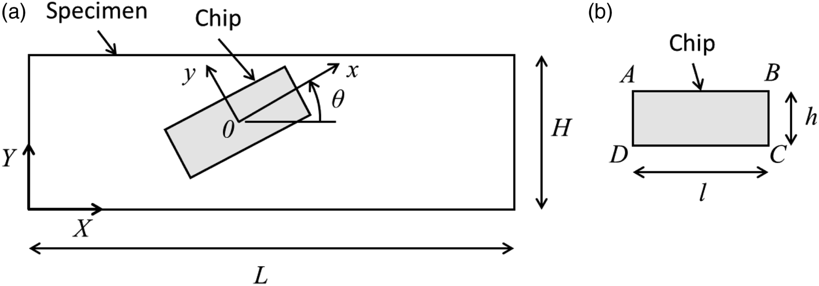
Once a chip is positioned and oriented, the elements within the area covered by that chip in the


Elements in the area covered by a chip meet the criterion


The first chip to be placed will always occupy space associated with elements from the first layer. Thereafter, when a chip (or part of a chip) is placed in an occupied space, there will be superposition. To determine the Example of a simple model having 16 elements, where three chips are positioned randomly. For simplicity, chip orientation is not considered in this illustration.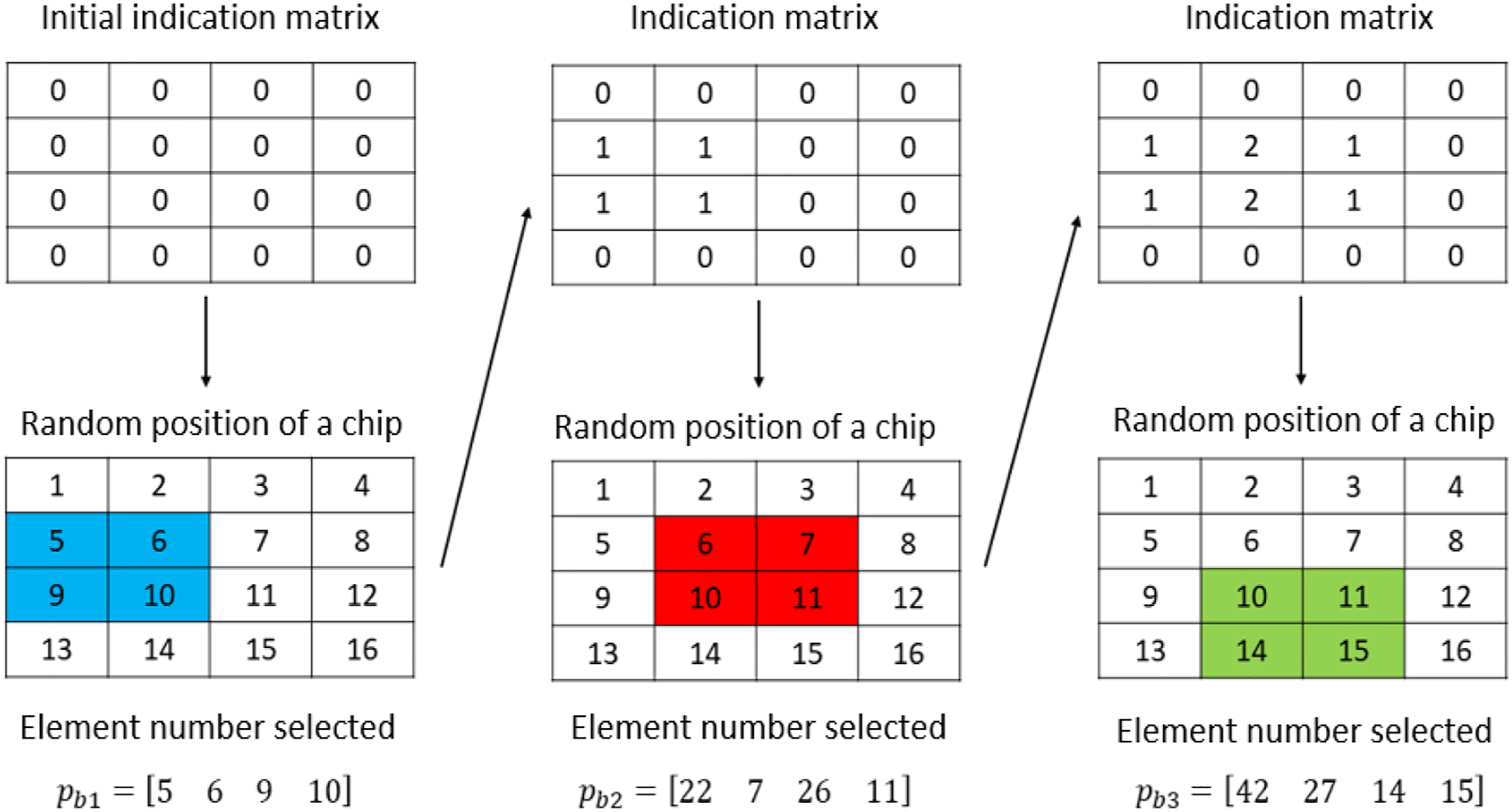

Once an element is linked with a chip, the randomly allocated chip angle Example of a discretized model. Colours represent the coordinate systems assigned to the elements.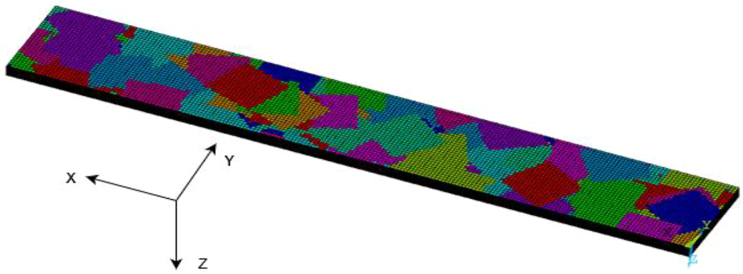
In the FE model, since adjacent elements share nodes, mating chips are considered perfectly bonded to each other, surface-to-surface or edge-to-edge, depending on the case. Therefore, load is transferred between chips by surface-to-surface shear but also by edge-to-edge tension. This reduces the stress concentration that would normally appear in a shear-lag zone. However, in the physical specimens, the chips get thinner near their edges, 11 where they are “squeezed” between their upper and lower neighbours, and the stress concentration is effectively reduced. The simplifications made in the FE model, while ensuring computational efficiency and modelling simplicity, do not affect its capacity to predict the behaviour of the DLF composites under study.
Model definition
Mechanical behaviour
Mechanical properties of the composite chips used for numerical analysis. 14
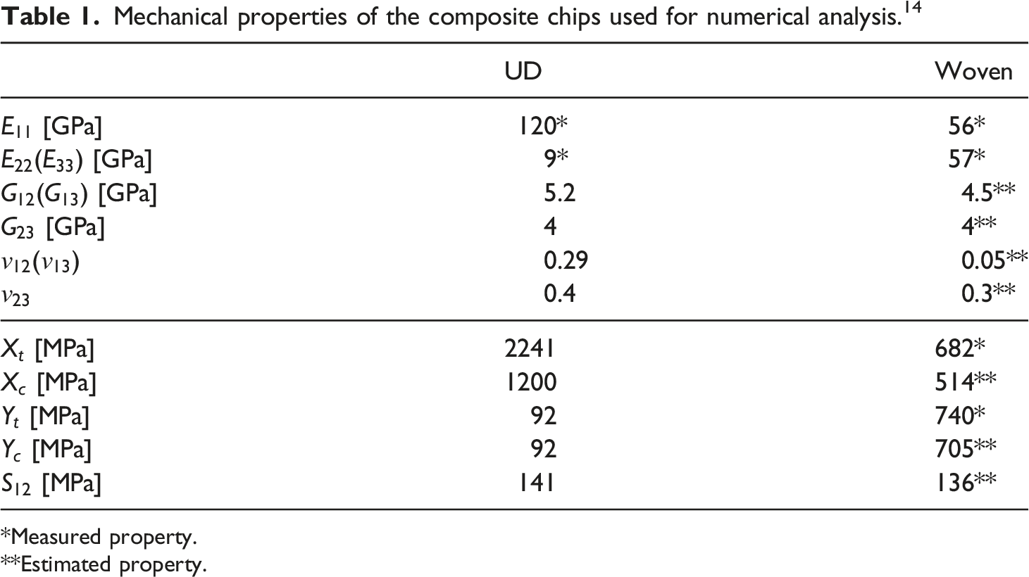
*Measured property.
**Estimated property.
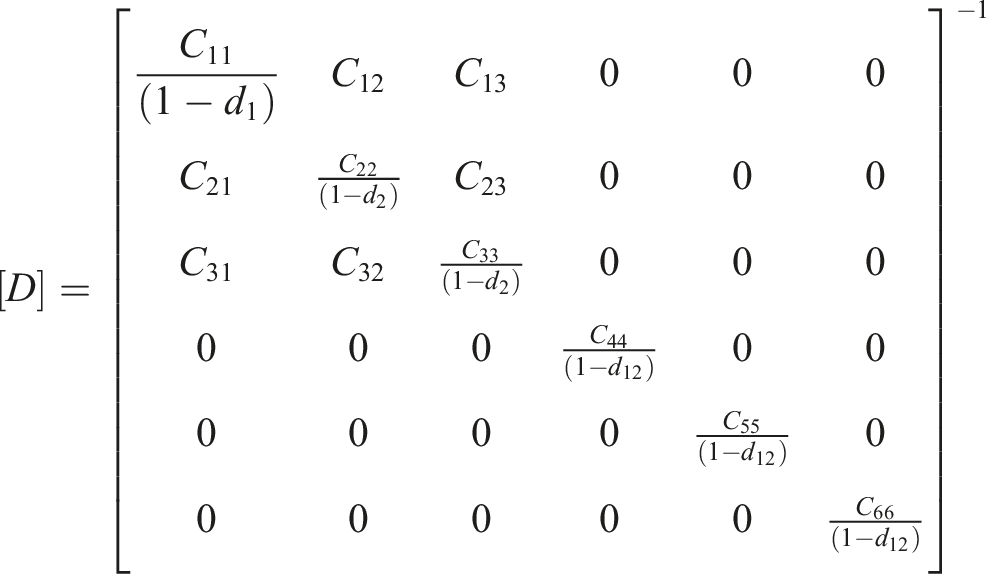
A progressive damage model, already available in ANSYS, was included to represent the non-linear fracture behaviour of the composite. Three variables track damage and reduce the rigidity of the elements that have experienced failure: damage in direction 1 (
Puck’s model
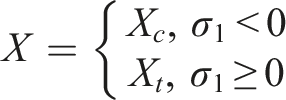
To determine whether the UD-fibre composite material has suffered damage, the modified Puck failure criteria
13
were used. According to this model, the failure criterion in direction 1 (i.e., direction parallel to the fibres) is defined by
The failure criterion in direction 2 (i.e., failure of the matrix) is defined by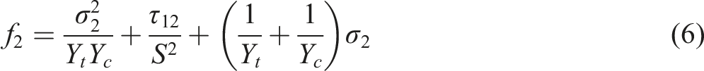
The element fails when
Maximum stress model
To determine whether the woven-fibre composite material has suffered damage, the maximum stress model
13
was used. This model was used for woven fibres because Puck’s failure criteria considers that there are no fibres in direction 2, which is not the case for woven fibres. The failure criteria in plane 12 are defined by

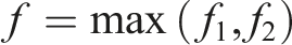
The maximum stress model is therefore defined as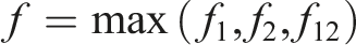
The element fails when
These damage criteria do not consider complex failure mechanisms such as tow-tow delamination or transverse cracking within tows that may occur in woven-fabric composites. 15 This homogeneous (effective continuum) properties modeling approach was selected for its ease of implementation, its efficiency, and its relatively good accuracy, which are important factors for industrial applications.
Damage variables
Damage variables are used to reduce the stiffness of the material at the locations where failure has occurred. This reduction in stiffness represents progressive damage, i.e., the evolution of damage in the material. In the present model, damage variables can take one of two possible values, 0 or 0.95, where 0 represents no damage and 0.95 represents the maximum damage to the element. This is mathematically expressed as
Conditions of the analysis
Due to the random chip distribution in the model, several simulations were performed for each chip type, UD and woven. This allowed to perform statistical analyses on the results, as well as to validate the model by comparing its predictions with previous experimental results.
11
The boundary conditions shown in Figure 4 were prescribed to represent the conditions of the tensile tests. Uniform displacement in positive Prescribed boundary conditions of the finite element model.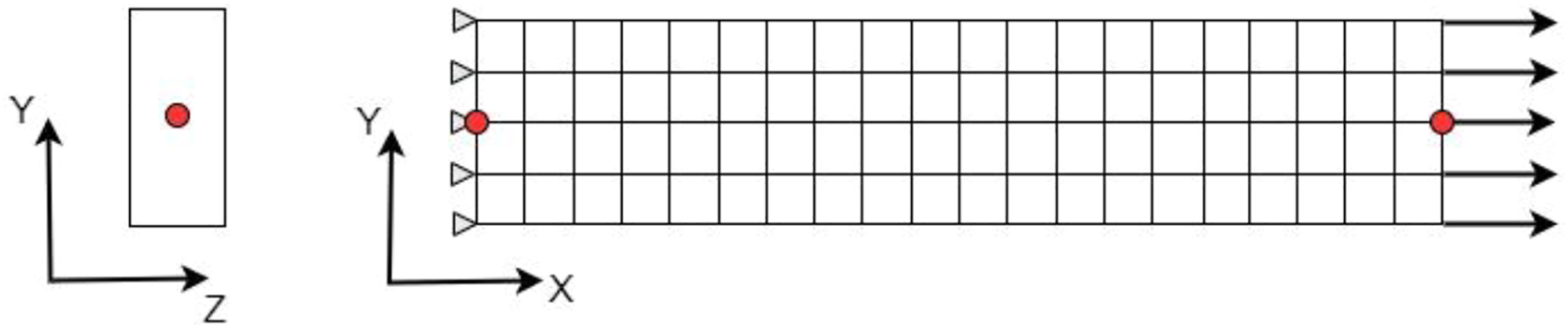
For the simulation, automatic step adaptation was enabled, with an initial step of 0.01, a minimum step of 10−4 and a maximum step of 0.1. Convergence difficulties were mitigated by a viscous regulation scheme with a stabilization factor of 10−4, which ensured that the tangent stiffness matrix was positively defined for sufficiently small increments. Complete material failure was assumed when the model diverged.
Results and discussion
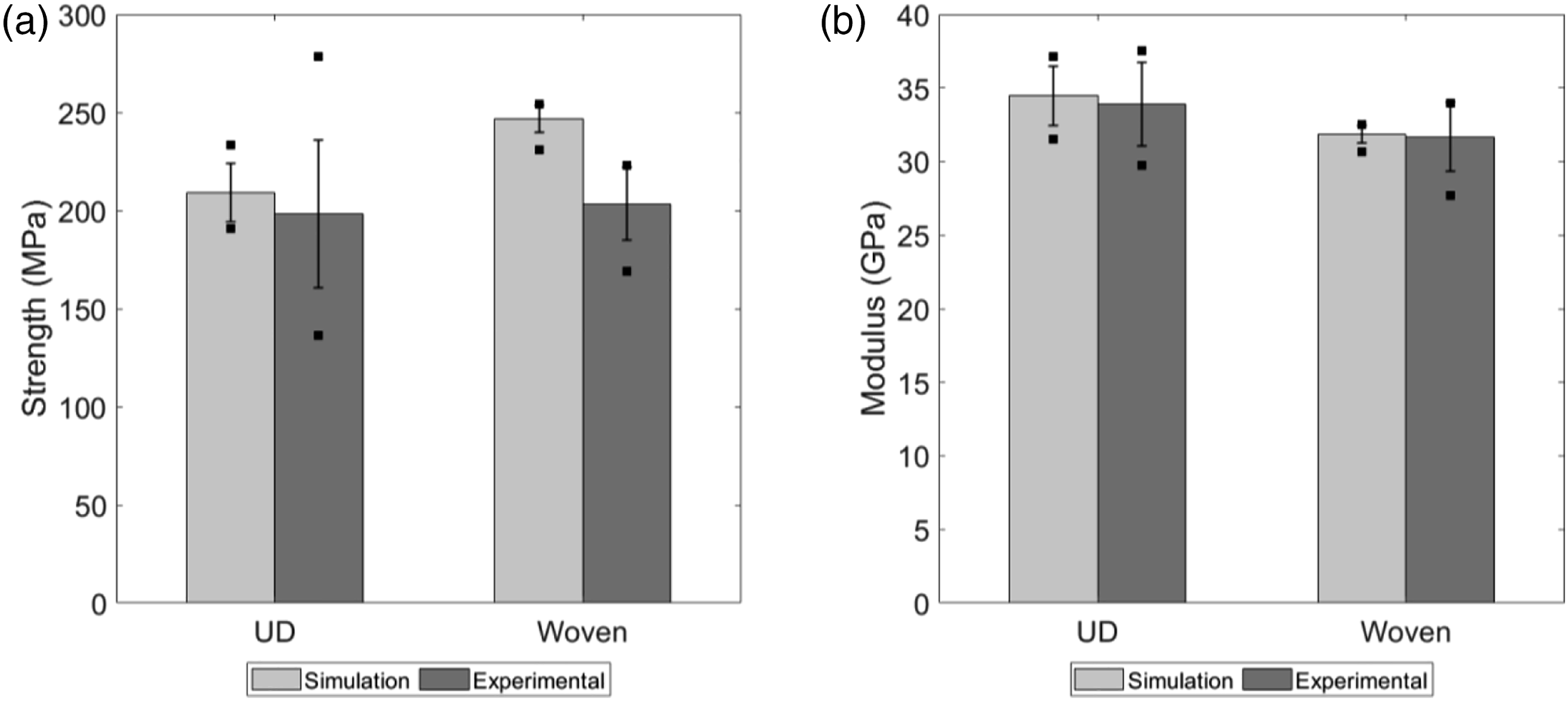
Experimental and predicted tensile curves for the two materials are shown in Figure 5. In order not to overload the graphs, only five curves of each type are presented. To better compare the results, mechanical properties obtained from these curves are shown in Figure 6, where the bars represent the average, the error bars represent the standard deviation, and the square points represent the extreme values. Tensile strengths and moduli are compared in these graphs. The data of Figure 6 is based on the results of ten simulations for the UD chips and ten simulations for the woven chips. Tensile curves of experimental and simulated specimens for (a) unidirectional chips and (b) woven chips. The vertical axis represents the effective stress on the tensile specimen. The red curves, identified as Sim1…5 in the legend, are results from the simulations. The gray curves (Exp1…5) represent experimental results. Comparison of the mechanical properties of unidirectional and woven chips. (a) Tensile strength and (b) tensile modulus.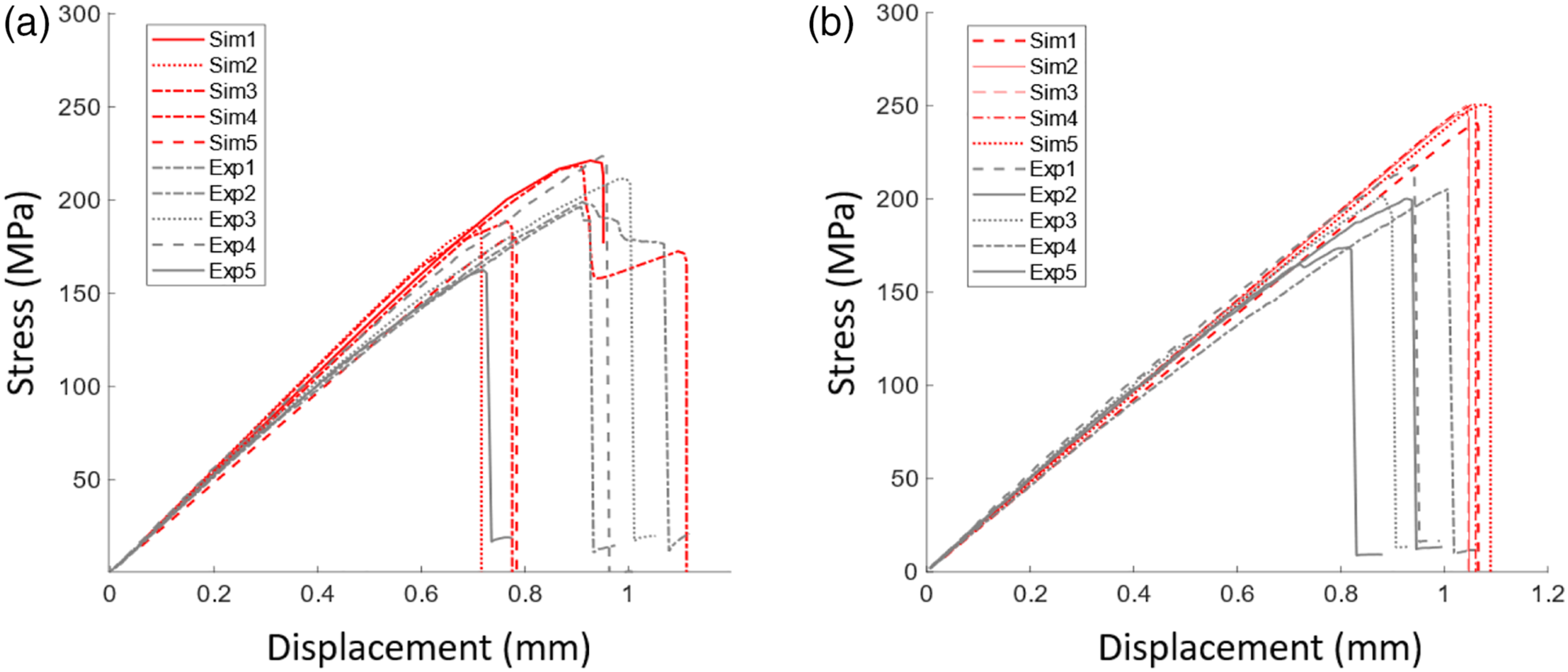
P-values obtained for the comparison between numerical and experimental analyses.
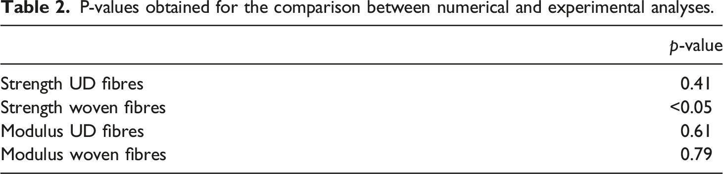
The results of Figure 6 show that the model can accurately predict the modulus of composites made with both types of chips (Figure 6(b)). However, the model significantly overestimates the strength in the case of the woven fibres (Figure 6(a)). Strength predictions strongly depend on the damage model and this result may be attributable to the fact that the maximum stress criteria were employed for woven chips, as discussed in Section Maximum stress model. On the other hand, Puck’s model adequately represents the behaviour of the UD-chip composite. Despite the overestimation of the tensile strength of the woven-chip composite, it is still possible to analyze the failure modes of both types of chips by observing trends. The variability in the test results is reasonably well predicted by the model, except in the case of the strength of the UD-chip composite, where the variability from experimental testing is large.
The numerical model predicts a trend similar to the one observed from the experimental tests of Belliveau et al. 11 Woven-fibre chips, having “more isotropic” in-plane mechanical properties, significantly reduce the variability of the strength and modulus of the DLF composite compared to highly anisotropic UD-fibre chips.
Figure 7 shows predictions of failure from the five possible modes: tension and compression in directions 1 and 2 as well as in-plane shear 12. Figure 7 reveals that the failure of specimens with UD chips is mainly caused by the rupture in direction 2 of the chips, i.e., the direction perpendicular to the fibres. Shear failure is also very apparent. However, fibre breakage is practically non-existent. On the other hand, specimens with woven chips exhibit significant damage in both directions (1 and 2), as well as damage caused by shear. Remembering that there are fibres aligned with both directions in woven chips, these chips suffer much more uniform damage compared to UD-fibre chips, thus reducing the potential for weaknesses in the specimens. Failure modes predictions for the (a) UD-fibre DLF composite and (b) woven-fibre DLF composite. The scale represents the damage, where 0 means no damage and 1 means complete rupture of the element.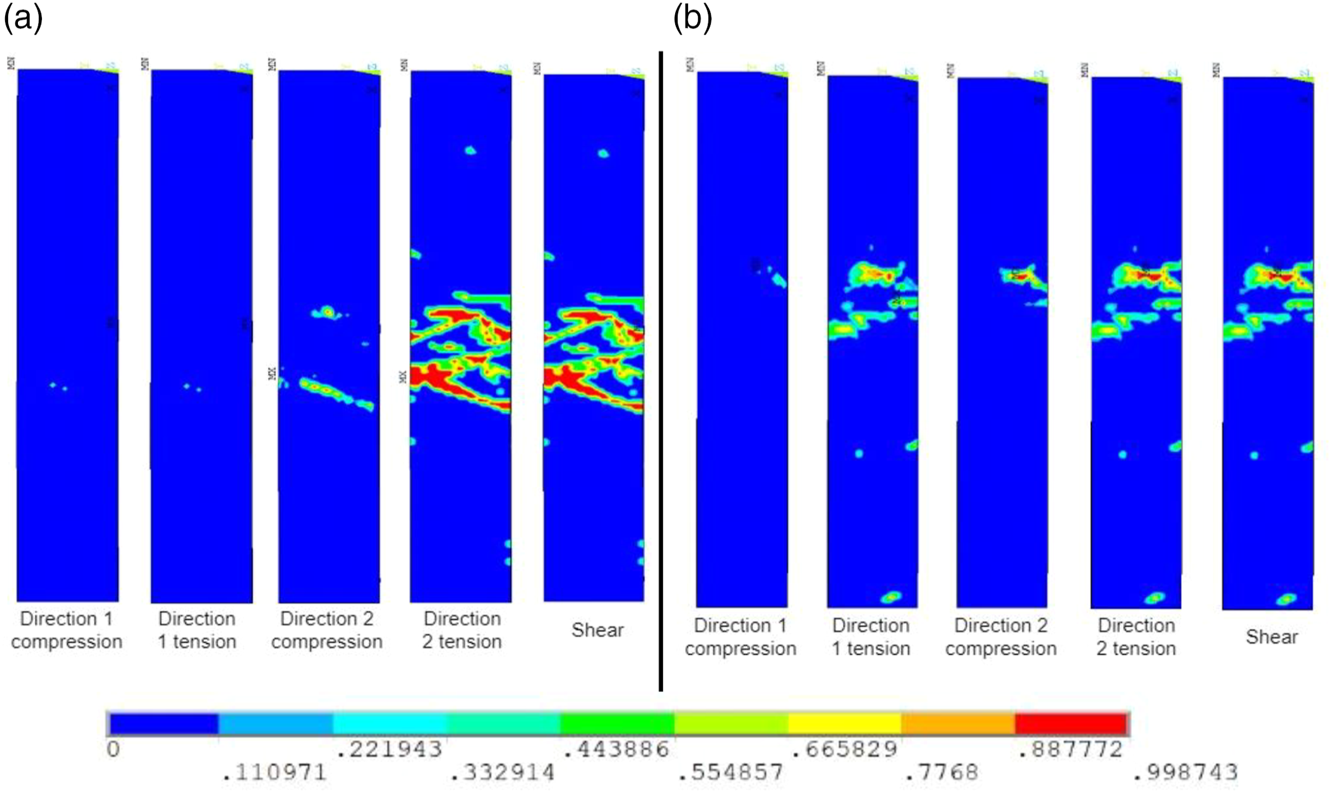
By using 3D elements, the full 3D behaviour of the specimen can be captured, with out-of-plane displacements, which are shown in Figure 8. The displacements shown correspond to an axial elongation of 0.43 mm of the specimen, for which no damage has yet occurred. The UD-fibre specimen shows some positive and negative out-of-plane displacements resulting in surface waviness. This is attributable to the significant stiffness variations within the specimen. By contrast, the woven-fibre specimen yields a much smother out-of-plane displacement distribution along its axis. The twist in the samples is attributable to the non-symmetric, random layup. Out-of-plane displacements (in mm) for an axial elongation of 0.43 mm. (a) UD-fibre chips (b) woven-fibre chips.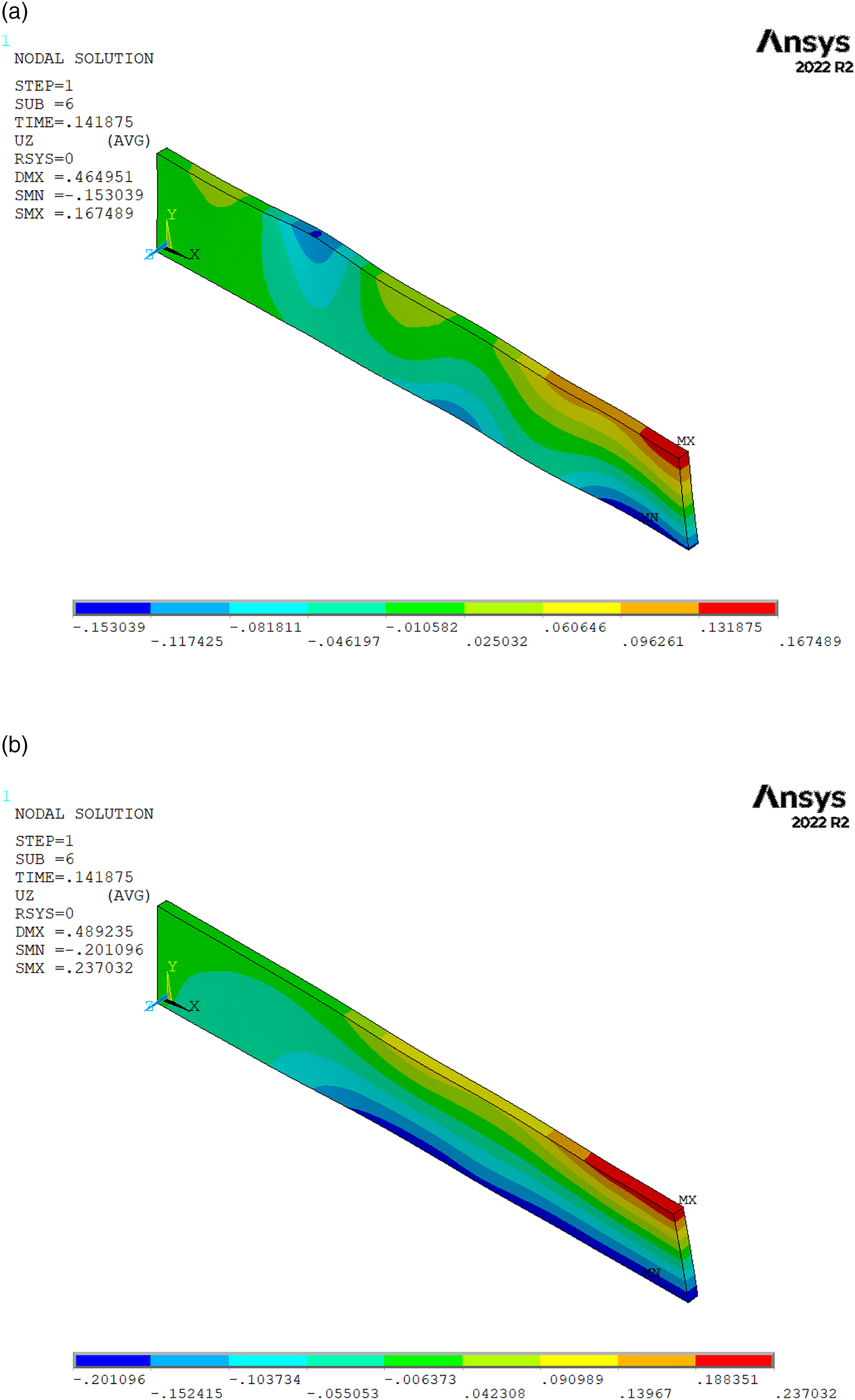
Conclusion
This study presented a simple but efficient way to simulate the mechanical behaviour of DLF composites made from pre-impregnated chips. The proposed FEM, based on 3D solid elements, was fully developed using ANSYS software without requiring external means to discretize the domain. By using progressive damage features, the model can predict the strength and modulus of DLF specimens. The developed model is simple to implement and require relatively low calculation time.
The proposed model was used in a comparative analysis to understand the difference in behaviour between DLF composites fabricated from UD chips and woven chips. From this analysis, it was concluded that the improved isotropy of the in-plane properties provided by the woven-fibre chips have the potential to reduce variability and therefore increase the mechanical performance of DLF composites. The failure modes observed were mainly matrix (chip direction 2) and shear failure for the UD-fibre DLF composite compared to damage in chip directions 1 and 2 for the woven-fibre DLF composite.
Footnotes
Declaration of conflicting interests
The author(s) declared no potential conflicts of interest with respect to the research, authorship, and/or publication of this article.
Funding
The author(s) disclosed receipt of the following financial support for the research, authorship, and/or publication of this article: This work was supported by the Natural Sciences and Engineering Research Council of Canada (Discovery Grant to B.L.) and by the Faculty of Graduate Studies, Université de Moncton [Grants to B.L. and G.L.].