
Abstract
Objective of the present study is the definition of a continuum damage mechanics material model describing the degradation of fiber reinforced materials under fatigue loads up to final failure. Based on the linear elastic framework, a brittle damage model for fatigue conditions is derived, where the damage constitutes the only nonlinearity. The model accounts for damage effects by successive degradation of the elastic moduli. Assuming that material damage is driven by microplastic work, a stress-driven damage evolution equation is defined. For generality, a fully three-dimensional formulation on single ply level is employed. The model is implemented into a finite element program. In a validation against experimental data on filament-wound carbon fiber reinforced material, the model proves to provide a good numerical approximation of the damage during the cyclic loading history up to final material failure.
Introduction
Fiber reinforced plastics of the carbon or glass fiber reinforced (CFRP or GFRP) types, as well as other types, are important structural materials in all fields of lightweight construction. From the classical field of the aerospace industry, their area of application today ranges over all kinds of road and rail transportation, the naval industry and even civil engineering applications to the field of wind energy and numerous types of special applications where high stiffness and strength of the material at low specific weight is required. Especially, in transport applications and for all kinds of machinery, the assessment of the fatigue limits of the material in addition to the static load limits is an essential part of the integrity assessment.
Due to their distinct microstructure, the fatigue response of fiber reinforced plastics is more complex compared to metals and other structural materials. Furthermore, it depends on the type of the fiber and matrix microstructure, whether of the continuous unidirectional, woven or nonwoven, random or aligned short fiber reinforced type. It has been shown by Talreja 1 in his now classical contribution that the failure of fiber reinforced plastics under cyclic loads within the fiber direction is governed by static fiber failure, matrix and interface cracking. In this context, the matrix is subject to fatigue effects whereas the fibers exhibit only minor fatigue effects or even no fatigue degradation at all. For high-modulus fibers, static fiber failure is the leading failure mechanism since the stiff fibers shield the matrix from deformation such that no fatigue response in the classical sense is obtained. For softer fibers, fatigue degradation of the matrix becomes the leading mechanism. As a result, a classical Wöhler-type 2 S-N-curve response is obtained. Experimental investigations on GFRP materials, by Talreja, 3 yield that up to 200 load cycles, fiber failure is the dominant mechanism whereas matrix cracking normal to the loading direction becomes the dominant mechanism at the later stages. Under off-axis loads, the leading failure mechanism turns to matrix and interface degradation, already for small load and fiber angle misalignments. Similar mechanisms are active in short fiber composites, especially in case of randomly oriented fibers. In multidirectional laminates, matrix failure in the form of inter-ply delamination constitutes an additional active failure mechanism.3,4
A specific effect in the fatigue of fiber reinforced (and other) composite materials is the possible development of a significant stiffness degradation in the initial range of the cyclic loading history. Usually, this initial degradation comes to a stand-still after several hundreds of load cycles such that the initial rapid degradation zone is followed by a long range area with (nearly) constant stiffness, lasting through most of the fatigue lifetime. When the fatigue limit is approached, a rapidly increasing development of stiffness degradation up to a complete loss of stiffness at material failure is observed. Using computed tomography, this effect has been studied on the microscopic level by Arif et al.
5
for injection molded short fiber reinforced PA66GF30 as well as by Garcea et al.
6
on
In engineering application, the assessment of structures under fatigue load is typically performed in terms of the classical Wöhler-Miner2,11 S-N-curve type approach. For this purpose, Bond 12 proposed a modified Miner rule in conjunction with rainflow counting for GFRP materials. An alternative nonlinear Miner rule for short fiber composites has been proposed by Dreißig et al. 13 Brunbauer et al. 14 as well as Gude et al. 15 analyzed the fatigue of fiber reinforced materials using a load cycle dependent Puck's criterion. A similar approach based on the Tsai-Hill criterion has been provided by Jen and Lee. 16 Hartmann et al. 17 as well as Zago and Springer 18 investigated the precision of fatigue predictions based on damage accumulation rules of the generalized Miner type for different structural components experimentally and thereby proved their general applicability.
The advantage of generalized Wöhler-Miner type models is their high numerical efficiency since they can be applied during the postprocessing of static structural analyses. On the other hand, they inherently do not account for possible stiffness degradation during the fatigue process and thus do not account for possible stress redistribution due to inhomogeneous stiffness degradation. Furthermore, their application to load histories with strongly variable nonharmonic load cycles is difficult. For this purpose, continuum damage models tracking the local fatigue degradation as part of the constitutive model are advantageous, including these effects in a natural manner. An early continuum damage model for two-dimensional anisotropic composites has been presented by Matzenmiller et al. 19 Nevertheless, in a similar manner as a recent model proposed by Hund et al., 20 the concern of the model is static damage development due to overloading rather than fatigue damage. A continuum damage mechanics model for fatigue of composites has been proposed by Kennedy et al. 21 Their model employs cycle number driven damage accumulation relations based on Puck's criterion in conjunction with the Miner rule, also accounting for the S-shaped stiffness degradation during the fatigue lifetime. A similar, but more simple model has recently been proposed by Mohammadi et al. 22
Due to their load cycle driven formulation of the damage accumulation law, the models proposed by Kennedy et al. 21 and Mohammadi et al. 22 are restricted to at least blockwise harmonic fatigue loads in the same manner as the model proposed by Shokrieh and Taheri-Behrooz. 23 The present study is concerned with an alternative model, applicable to all kinds of fatigue load histories. For this purpose, a three-dimensional generalization of Matzenmiller et al. 19 brittle damage model, coupled with a damage accumulation equation driven by microplastic dissipation is proposed. Assuming a Ramberg and Osgood 24 type law for the microplastic deformation, all dissipative effects can be estimated from the elastic deformation, resulting in an efficient formulation for the constitutive equation where the damage accumulation provides the only nonlinear effect, thereby generalizing an earlier approach by the authors.25,26 The model is implemented into the finite element method and validated against an experimental data base on a filament wound carbon epoxy composite material.
Damage degradation model
Basic assumptions and hypotheses
The objective of the present contribution is the definition of a continuum damage mechanics material model for fiber reinforced composites under harmonic or nonharmonic fatigue loads. The model should be able to describe the final material failure as well as a possible continuous stiffness degradation of the material, reported in the literature for some kinds of fiber reinforced plastics. The definition of the model is based on the following basic assumptions and hypotheses:
The basic material response is linear elastic as it is the case for classical unidirectionally CFRP epoxy matrix composites or similar materials. The only relevant nonlinearity to be considered is the degradation of the elastic moduli in the anisotropic formulation of Hooke's law. The dominant damage mechanism is the formation, growth, and coalescence of microcracks in the matrix between the fibers or breakage of individual fibers and subsequent formation of microcracks in the neighboring matrix. The evolution of damage is assumed to be driven by dissipation of microplastic work. In this context, microplasticity is defined as a contained plasticity below the macroscopic yield limit of the material with plastic strains, which are much smaller than their elastic counterparts. Hence, the microplastic deformation is negligible compared to the elastic deformation. Nevertheless, despite the rather small plastic strains and thus the rather small plastic dissipation in individual load cycles, repeated loading and unloading at larger numbers of load cycles may result in a cumulative dissipation of a considerable amount of plastic work, resulting in considerable material damage. Stiffness degradation may occur from the beginning of the cyclic loading. The degradation of the material stiffness develops in a nonlinear manner with a possible distinct drop in the initial range, caused by the instantaneous growth of pre-existing micro-defects under the first loading sequences. The initial drop is followed by a long range with minor additional degradation. Prior to the final material failure, the second range is followed by a range with rapidly increasing stiffness degradation. In coincidence with the anisotropy of the material's microstructure and effective elastic properties, all damage and degradation effects are suspected to be strongly anisotropic.
These hypotheses are assumptions deriving from experimental observations from literature. Their approximation quality needs to be checked by application of the material model to be derived against experimental data. Under consideration of the mentioned hypotheses, the continuum damage model is formulated on single ply level. By this means, interaction of neighboring plies and thus also fatigue driven delaminations are accounted for in a natural manner.
Damage variables
The damage effects on the macroscopic stress–strain response of the material are modeled in the Kachanov
27
and Lemaitre
28
sense. For this purpose, the macroscopic “effective” stresses are defined by

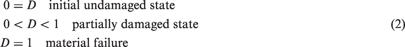
Assuming that microcrack formation, growth and coalescence is the relevant damage mechanism, the damage parameter D is related to the ratio of the crack area oriented normally to the stress direction to the total area of the cross section. However, D is not identical to this relation due to the inhomogeneity of the material on microstructural level as well as the possible development of stress and strain concentrations at the crack fronts of the microcracks.
For the present problem of an anisotropic fiber reinforced material, three independent damage variables D1, D2, and D3 for crack orientations normal to the three coordinate axes as sketched in Figure 1 are required. Using the standard definition of the coordinate frame with the x1-direction coinciding with the fiber direction, D2 and D3 are related to the formation of interfiber microcracks (possibly also involving the fiber and matrix interfaces) whereas D1 describes the effect of microcracks normal to the fiber orientation thus also accounting for fiber damage and breakage.
Definition of damage variables.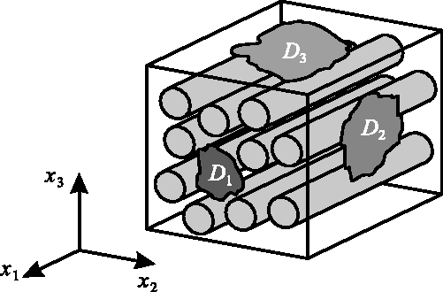
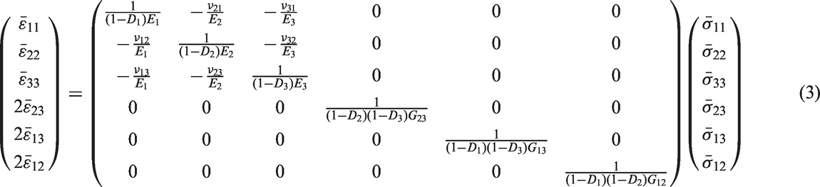
Apart from the damage effects, the material is assumed to exhibit a linear elastic response and thus can be modeled by Hooke's law in its orthotropic form. Introducing the damage variable according to Figure 1 and using equation (1), the orthotropic Hooke's law can be written as
with the Young's and shear moduli E
i
and G
ij
as well as the Poisson's ratios ν
ij
as the elasticity parameters for the undamaged material.25,26 Retaining the symmetry of the compliance matrix, equation (3) can be considered as Hooke's law, where the elastic constants are degraded according to


Damage evolution
One-dimensional considerations
The three damage variables D
i
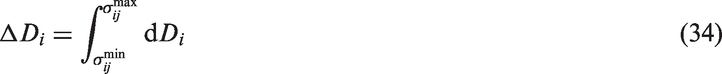
in equation (3) form additional field variables for which additional equations are required. These equations are provided in terms of evolution equations, describing the evolution of damage from a prescribed initial value to the actual value in the computed time history. According to the considerations in Section “Basic assumptions and hypotheses,” it is assumed that the increase

In this context, the microplastic deformation is a plastic deformation induced by limited microscopic gliding of polymeric chains in the matrix material, occurring at load levels below the macroscopic yield limit. Since these gliding effects are rather limited, the resulting microplastic strains are small compared to their elastic counterparts
Concept of micro plasticity.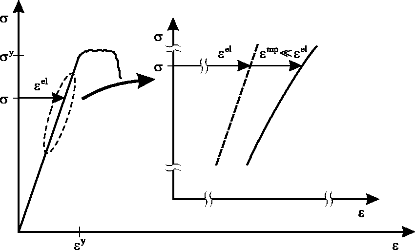

Assuming that the microplastic strains in one-dimensional form can be approximated by the Ramberg and Osgood
24
equation
Warping function.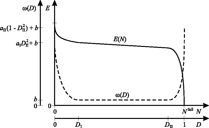


The definition (13) of the warping function results in an accelerated damage evolution for small degrees D of damage (i.e. in the initial range of fatigue loading) as well as for large degrees D of damage when the instant of final failure is approached.
Discussion
For illustration, the meaning of the one-dimensional damage evolution equation (12) is investigated in more detail. Consider for the moment a simplified form where the warping of the damage evolution according to Figure 3 is discarded by assuming


If a cyclic load is applied at a stress ratio of R = 0, the damage accumulation per stress cycle is obtained as

For a material failure after


Hence, in a double logarithmic representation, a linear relation between the logarithm of the stress amplitude and the logarithm of the numbers of cycles to failure is obtained as it is postulated in the S-N-curve concept. 2 By this interrelation with the well-established Wöhler-concept, the meaningful definition (12) of the one-dimensional damage evolution equation based on the microplasticity concept together with the assumption of a Ramberg–Osgood type power-law relation between stresses and microplastic strains becomes evident.
Three-dimensional formulation
For the numerical implementation of the fatigue degradation model, the one-dimensional form (12) has to be re-written to a fully three-dimensional version. For this purpose, it is assumed that each of the damage variables D1, D2, and D3 related to the three independent spatial directions x1, x2, and x3 is driven by all stress components σ
ij
, which act on the respective surfaces of the volume element in Figure 1. Assuming an additive decomposition of the effects of the individual stress components, the three-dimensional generalizations


For simplicity and in order to keep the overall number of material parameters within acceptable limits, it is assumed that the warping function
Numerical implementation
Implicit time integration
For application in fatigue assessment, the material model defined in Sections “Basic assumptions and hypotheses,” “Damage variables,” and “Damage evolution,” is implemented into the finite element method. Employing an incremental approach, the stress components


The application of the proposed fatigue damage model in structural fatigue assessment using the numerical implementation defined by equations (26) to (31) requires the simulation of the entire cyclic loading history. By this means, the model fully accounts for load history effects, random load amplitudes or other changes in the loading situation during the fatigue lifetime in a natural manner. Possible stress re-distributions due to an initial degradation of the material (Figure 3) or during the accelerating degradation in the vicinity of the final material failure are accounted for. The case of a stable fatigue crack growth is also accessible. Temperature change effects are accounted for by defining all material parameters to be temperature dependent, assuming a piecewise linear variation between discrete temperatures.
In order to keep the numerical effort for computation of the cyclic load history within acceptable bounds, a cycle jump technique is employed by restricting the numerical simulation to a number of individual cycles, each of which is representative for an individual part of the loading history. The damage evolution computed during these reference cycles is then multiplied by the number of cycles, for which the computation cycle is representative. In the numerical implementation, this technique is easily implemented by multiplying the damage increments
Due to the power law formulation (12) of the damage evolution equation, resulting in equations (20) to (22), damage is accumulated especially during those portions of the stress cycles featuring high stress levels. Therefore, care has to be taken to ensure that these portions of the load cycles are supplied with a sufficient number of time steps in order to ensure that the high stress parts of the cycles are resolved in a sufficiently fine manner. In the computations in Section “Numerical example,” it is observed that for harmonic oscillations usually eight equally spaced time steps per load cycle are the minimum number of time steps necessary for a convergent solution, except for cycles with rather high damage accumulation.
Explicit time integration
The numerical implementation with implicit time integration as defined in Section “Implicit time integration” requires an iterative solution of the material equations (26) and (27). The iterative solution has to be computed for each global iteration in each time step at each integration point in the problem. Thus, a significant numerical effort is required, especially since typically, a larger number of cycles need to be simulated with a sufficient number of time steps each. On the other hand, the material nonlinearity requiring this local iterative procedure in the present case is only weak. The only nonlinearity is caused by the damage evolution, which in most cases is limited in the individual time steps forming the individual load cycles.
For this purpose, an alternative implementation using the forward Euler time integration scheme is proposed by substituting equations (26) to (27) by


Due to the unavoidable requirement of small time steps during a load cycle in order to ensure that the temporal resolution of the high-stress ranges of the load cycles is sufficiently fine, the requirements imposed to the temporal discretization by the use of an explicit time integration do not impose an additional constraint. By avoidance of the need for an iterative solution of the material equations, a numerically much more efficient simulation procedure is obtained. Notice that explicit time integration is applied only on the material level, whereas a classical implicit finite element scheme is applied on the structural level.
Analytical damage accumulation rule
An alternative approach to the direct numerical implementation of the proposed damage model is a reformulation towards a generalized Miner 11 approach, which then can be applied in the postprocessing of a classical linear elastic structural analysis without consideration of any damage and degradation effects during the underlying linear elastic stress analysis.
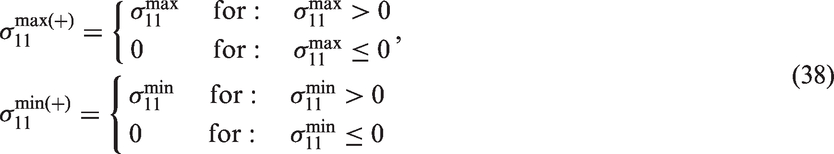
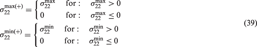
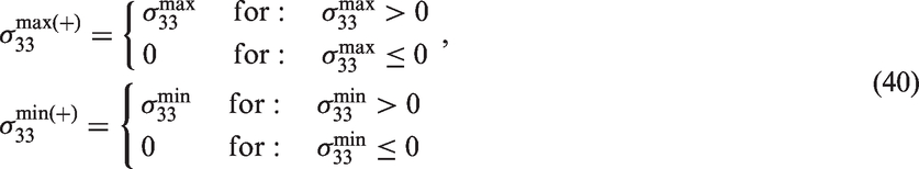
For this purpose, a harmonic fatigue load oscillating between the minimum and maximum local stress levels
Using this definition together with the general damage evolution equations (20) to (22) results in
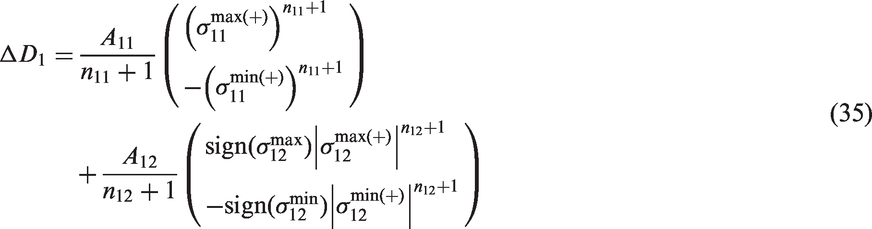
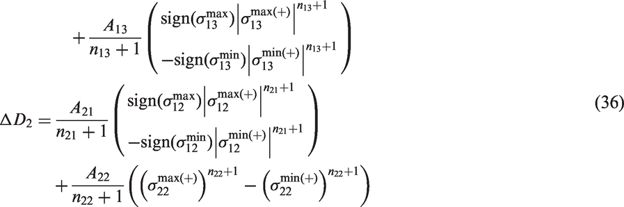
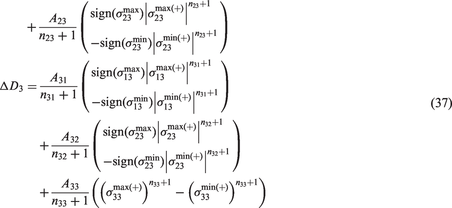
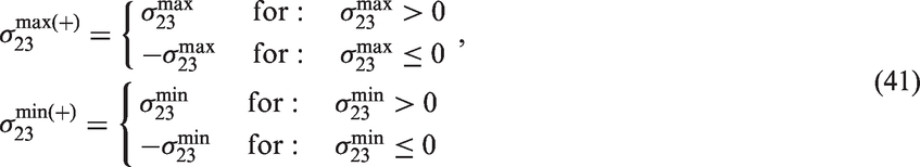

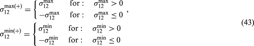
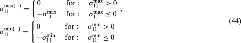
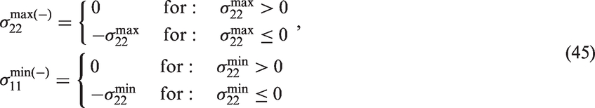

The analytical damage accumulation rules (35) to (37) together with the minimum and maximum stress definition (38) to (46) can be applied in the same manner as the classical Miner
11
rule to a numerically efficient life time analysis using the stress output of a static structural analysis of a single load cycle without consideration of damage effects as the stress input. Assuming a damage free initial state, the damage after k cycles at each position is then estimated as
As an alternative to a pure postprocessing analysis of the fatigue damage accumulation in the Miner
11
sense, the analytical damage accumulation rules (35) to (37) may also be used in a simplified cumulative analysis as proposed by Shokrieh and Taheri-Behrooz.
23
In this context, the stress response in the individual load cycles is computed in a simplified linear elastic analysis. Subsequently, the damage accumulation during the respective cycle is estimated from the damage accumulation rules. After completion of the load cycle, the accumulated amount of damage is applied at once and the analysis is continued with the updated stiffness matrix
Experimental data base
Reference material and methods
For validation of the damage degradation model developed in Section “Damage degradation model,” an experimental investigation has been performed. The reference material considered is a filament wound CFRP epoxy matrix composite as it is typically used for hydrogen or other composite pressure vessels. The fiber volume fraction is approximately
From the available unidirectionally fiber reinforced material with
The material has been characterized under quasi-static and cyclic loading conditions. For the quasi-static tests under tension, the specimens were clamped by a mechanical clamping system and tested in an electromechanical Hegewald and Peschke testing machine till failure. The experiments were performed under displacement control with a prescribed cross head velocity of Parallel clamping test rig.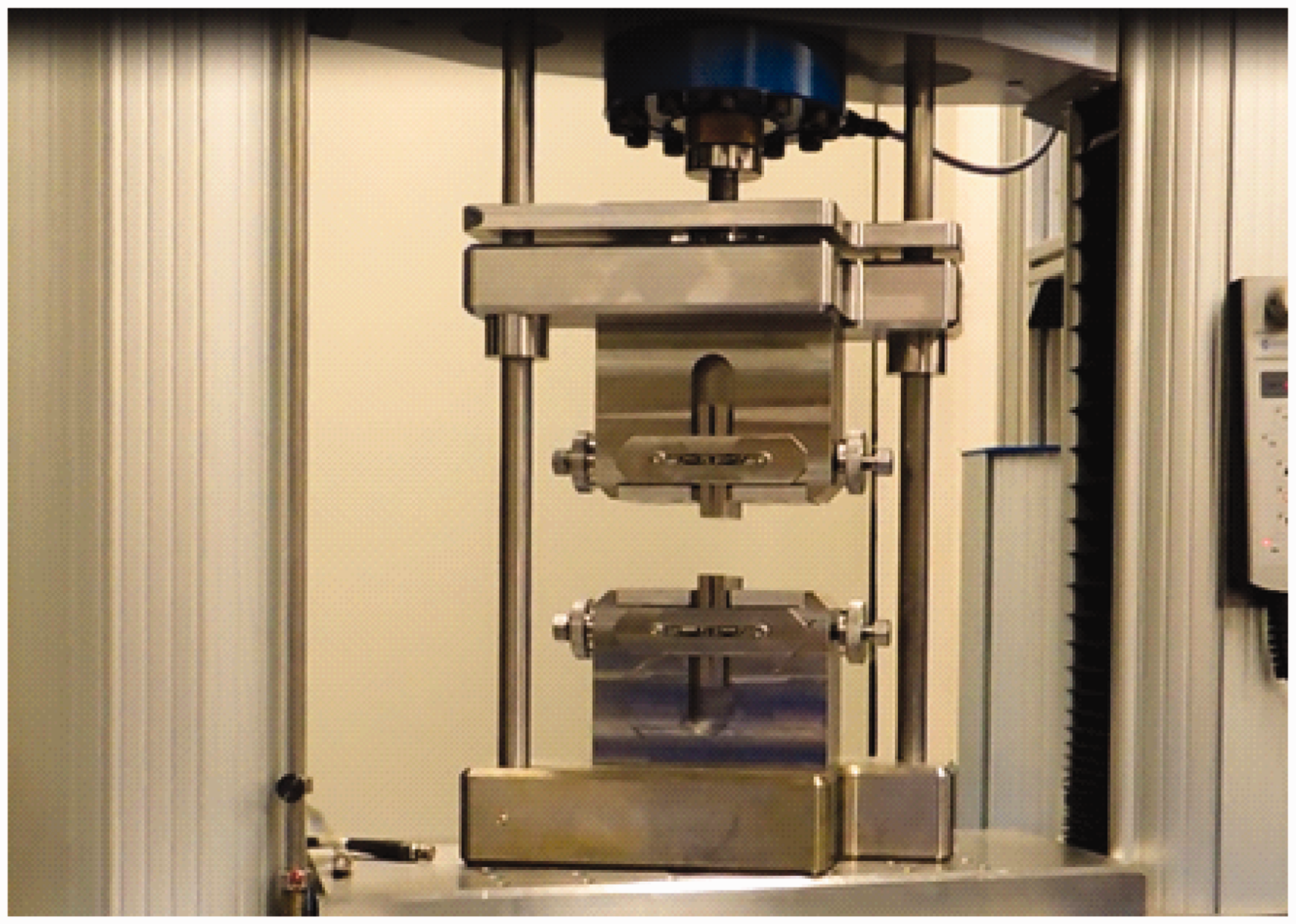
The experiments under cyclic loads were performed in a hydraulic MTS testing machine, using the same clamping systems. The tests were performed under tensile, compressive and alternating loads with stress ratios of
Results
The results of the quasi-static experiments are presented in Figure 5. The top three subfigures are related to tensile experiments whereas the results of the experiments under compressive loads are presented in the bottom three subfigures. In the left hand column of subfigures, the results of the experiments within the fiber direction are presented whereas the center and right hand columns of subfigures are related to experiments on unidirectionally fiber reinforced material perpendicular to the fiber direction and on the multidirectionally reinforced laminates respectively. In most cases, a brittle response is obtained where an approximately linear stress–strain curve ends with a sudden failure of the specimen without distinct plastic deformation. The only case with a distinctively nonlinear stress–strain curve prior to failure is observed in the case of UD material tested within the fiber direction for specimen no. ZU1-1.2-01B-02. Nevertheless, even for the case of the UD material tested under compression perpendicular to the fiber direction, all other specimens exhibit a visible, but limited amount of nonlinearity prior to final failure. For all fiber orientations, similar elastic stiffnesses are obtained in tension and compression.
Quasi-static stress–strain curves.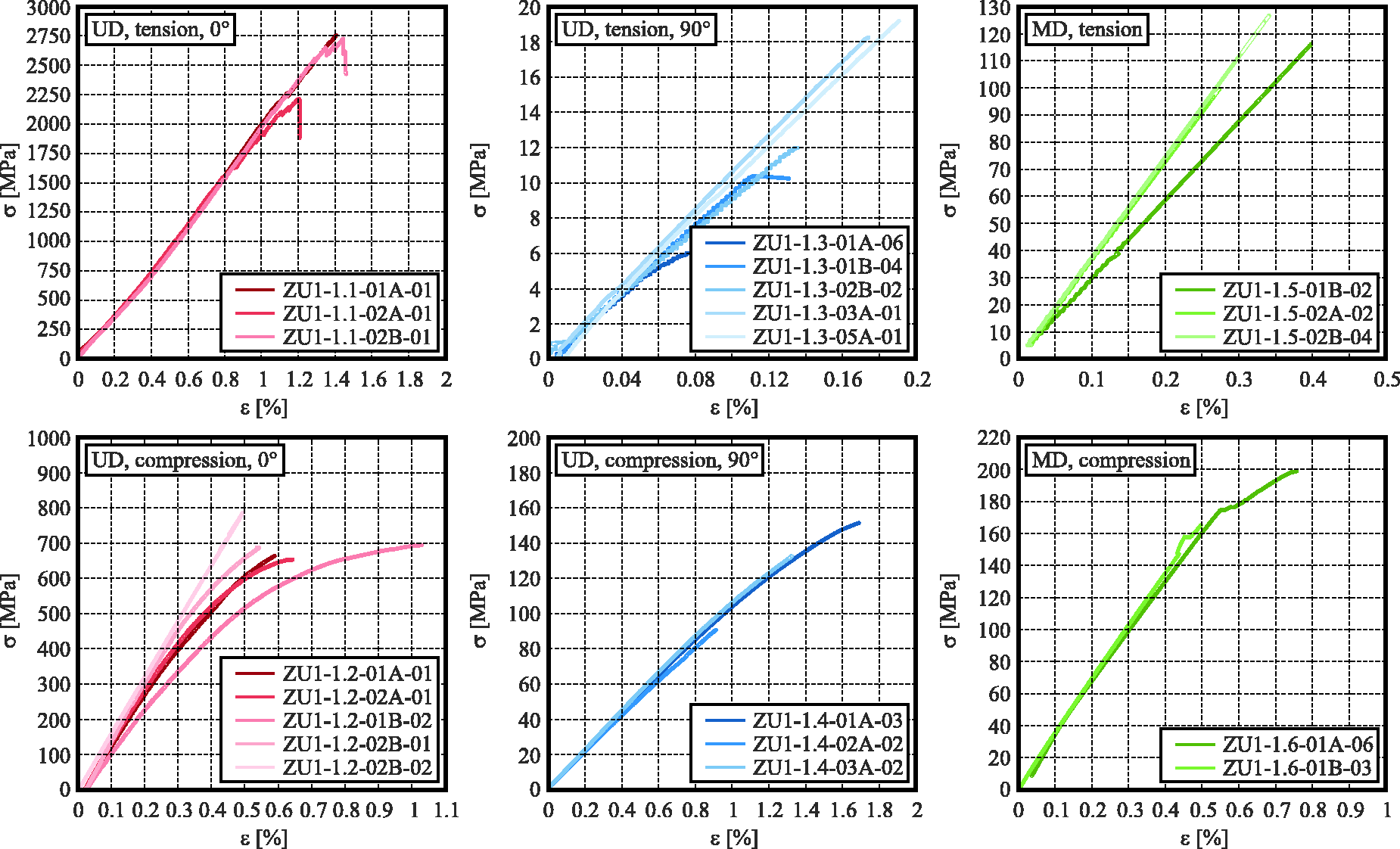
In Figure 6, the results of the fatigue experiments are presented. Again, the three columns of subfigures are related to unidirectionally fiber reinforced material tested within and perpendicular to the fiber direction and multidirectional laminates tested in the S-N-curves under cyclic loads.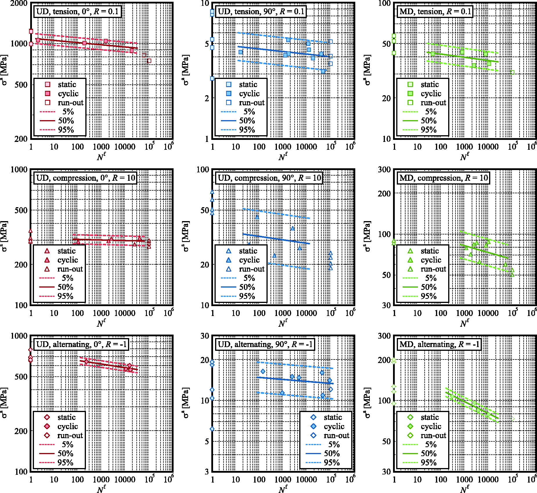
The determination of the stiffness degradation from the stress and strain envelopes during the fatigue loading tends to be difficile due to heavy white noise development. Further problems were encountered due to surface damage developing during the fatigue process, which increasingly disturbed the tactile strain measurement using clip gauges on the surfaces. The results are presented in Figure 7 where the normalized stiffness Degradation under cyclic loads.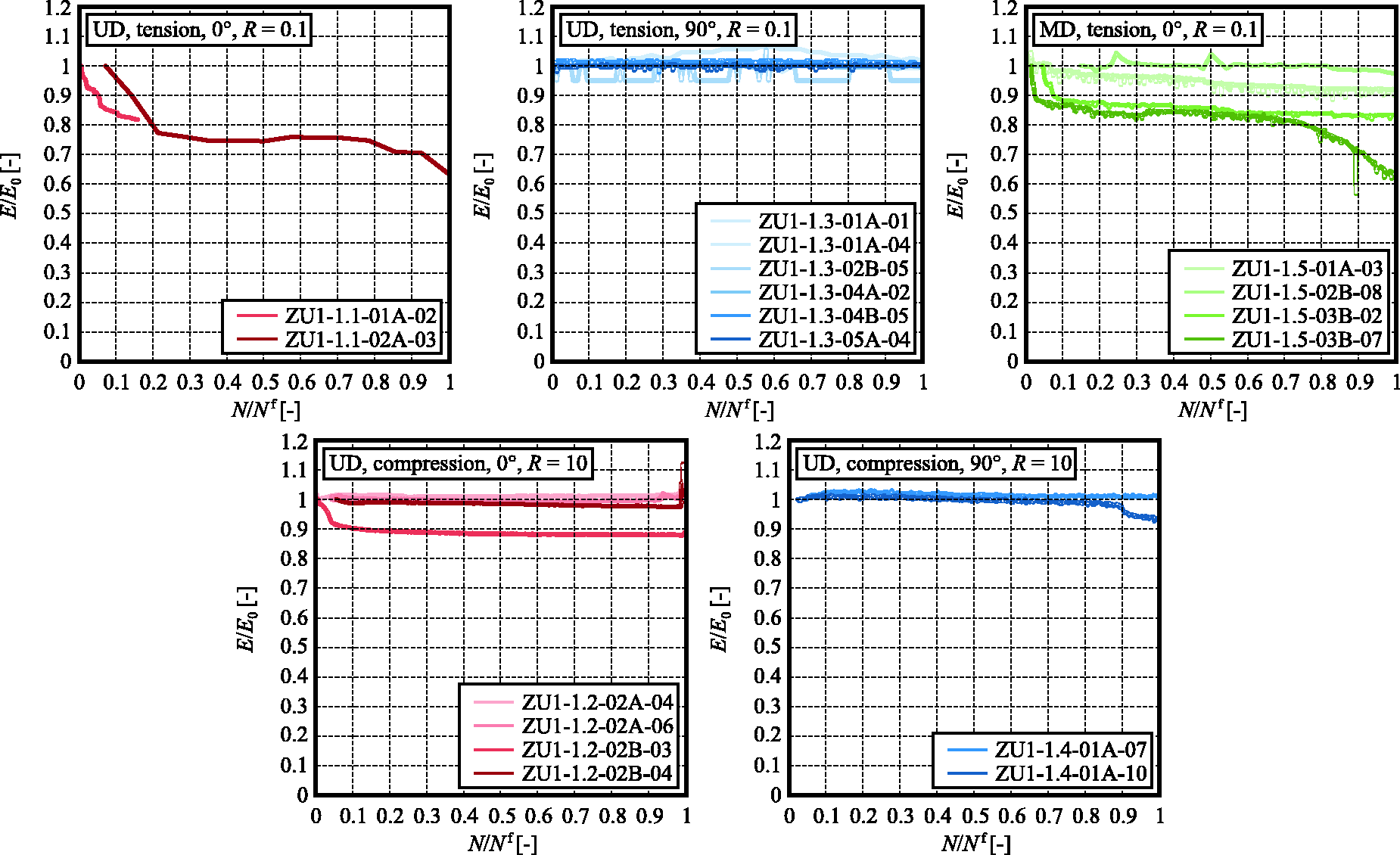
Numerical example
Parameter identification
As an exemplary application, the fatigue damage model defined in Section “Damage degradation model” is applied to the experimental data base described in Section “Experimental data base.” In a first step, the elastic moduli are determined as the secant moduli to the quasi-static stress strain curves between 0.05% and 0.25% nominal stain (Figure 5). Assuming initial transverse isotropy, the x2- and x3-directions are considered to be equivalent. Subsequently, the material parameters in the damage evolution equations (20) to (22) with (23) to (25) are determined by means of a reverse engineering approach. For this purpose, finite element computations are performed, where a single element is subjected to a cyclic unidirectional stress state with a sinusoidal characteristic. For acceleration of the fatigue degradation, a cycle jump technique with an acceleration factor of 1000 is used (i.e. a single computational cycle represents 1000 real loading cycles, see Section “Implicit time integration”). For reasons of computational efficiency, the explicit time integration scheme is employed. Nevertheless, competitive analyses based on both schemes show only negligible differences. The finite element analysis is continued until the element fails due to damage accumulation. In this context, the element is considered as failed, once any of the damage variables D1, D2, or D3 exceeds a level of 90%. This approximation definition is required since the theoretical “kink” in the stress–strain response when reaching a damage level of 100% had to be smoothed out mathematically in order to ensure numerical stability.
In the reverse engineering approach, the damage accumulation parameters are determined. Considering two stress levels within the relevant fatigue range in Figure 6, the respective parameters for the x1- and x2-direction are varied from guessed initial values, until S-N-curves fitting with the experimental data are obtained. Both, the tensile and compressive cyclic modes are considered. In this context, it is found that a common value for all exponents n ij in the damage evolution equations (20) to (22) provides a reasonable approximation. Hence, in order to reduce the number of parameters to a necessary minimum, all exponents n ij are assumed to be equal, keeping the scaling parameters A ij as the only different parameters for the different loading modes.
Material parameters.
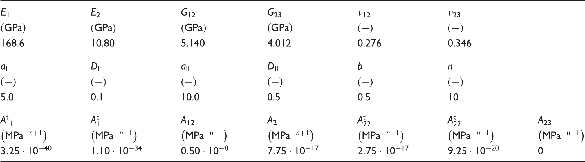
The resulting S-N-curves are presented in Figure 8. In all four cases, the numerical results for the determined data set are found in good agreement with the experimental data. Regarding the shape of the numerical S-N-curves, a linear material response in the double logarithmic representation is obtained (notice that the linear lines presented in Figure 8 are based on multiple data rather than by their end points only). The linear response is due to the assumption of the power-law definition (20) to (22) of the damage evolution equations. The fact that the well known linear shape of the S-N-curve in the double logarithmic Wöhler diagrams is obtained in the numerical simulations underlines the usefulness of the definition of the damage evolution in the present model.
Parameter determination.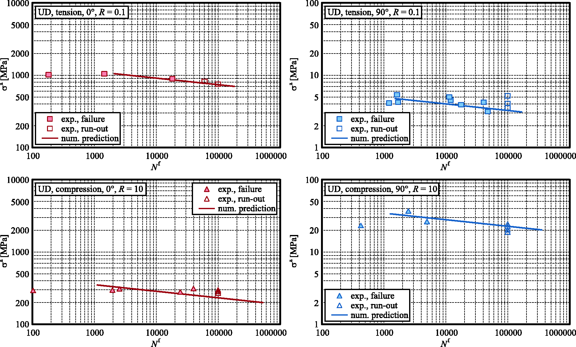
Validation
For a further validation and an evaluation of the transferability of the model and the parameter set presented in Table 1, the model with the previously determined parameter set is applied to the fatigue experiments from Section “Experimental data base” with alternating loads as well as to the experiments on multidirectional laminates.
The results for application of the model to the experimental data base on unidirectionally fiber reinforced specimens with alternating cyclic loads featuring a stress ratio of Validation–fatigue under alternating loads.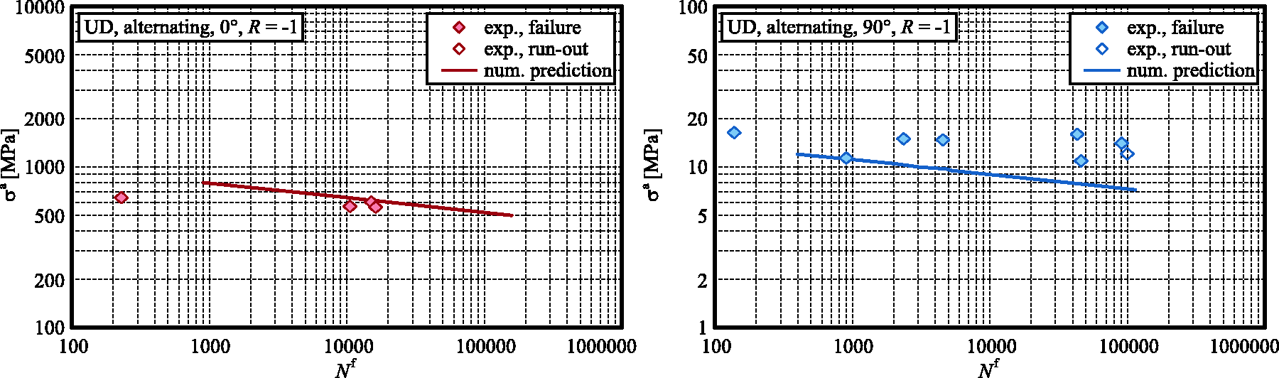
Multidirectional laminates recombining plies with different fiber orientation imply the development of more complex stress states in the individual plies even when loaded in uniaxial modes. Due to the interaction of the individual plies and the deformation constraints imposed to individual plies by their neighbors with alternative fiber and thus stiffness orientations, the stress states in all plies will be of the bi- or tri-axial type, irrespectively of the external loading direction. In order to investigate the response of the proposed damage model under more complex cyclic stress states, the model is applied to the experiments from Section “Experimental data base” on multidirectional laminates.
The results for stress ratios of R = 0.1 (tensile cyclic loads), 10 (compressive cyclic loads), and −1 (alternating cyclic loads) are presented in Figure 10. Again, perfectly linear S-N-curves in the double logarithmic representation of the Wöhler diagrams are obtained. For tensile cyclic loads, the experimentally observed fatigue strength is overestimated whereas an underestimate of the experimentally determined fatigue strength by the numerical results is observed for compressive cyclic loads. Nevertheless, in both cases, the deviation of experimental and numerical data is found in the same order of magnitude for typical scatter band widths obtained in the experimental investigation, especially when data sets consisting of a larger number of data are considered. For alternating cyclic loads with R = –1, a qualitative and quantitative agreement of experimental data and numerical results based on the proposed fiber reinforced fatigue damage model is obtained.
Validation–fatigue of multidirectional laminates.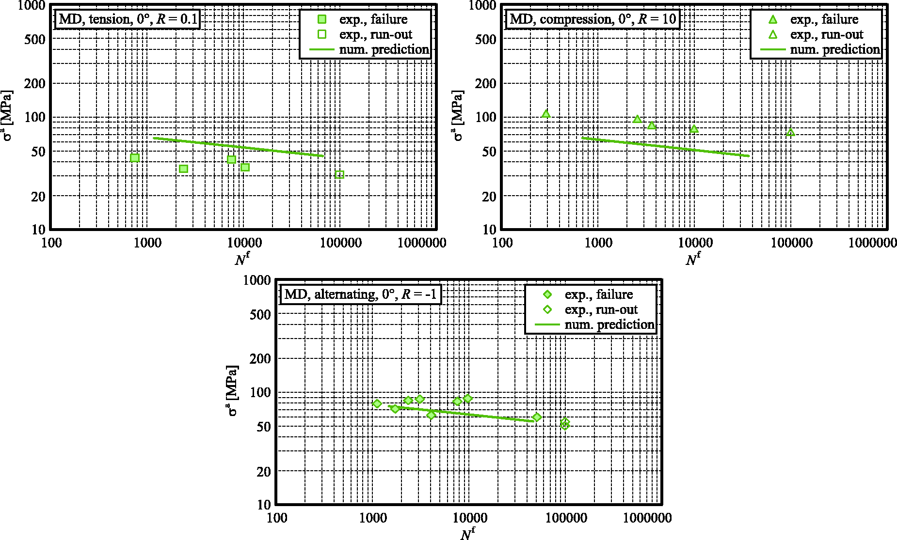
Conclusions
Objective of the present study is the definition of a continuum damage mechanics model for fatigue and degradation of fiber reinforced plastics. In order to keep the model and formulation as simple as possible, a brittle formulation based on the anisotropic linear elastic Hooke's law is employed. The model is enhanced by introduction of three independent damage variables, representing damage effects within three orthogonal planes. For the damage evolution, a power-law stress formulation depending linearly on the stress increment and in power-law form on the actual stress level is defined. This definition ensures that linear S-N-curves are obtained in the double logarithmic Wöhler fatigue strength diagram.
The model is implemented as a user defined material model into a commercial finite element system. Both, implicit and explicit time integrations are considered. In a comparison of the performance and accuracy, the explicit forward Euler time integration scheme is found to provide an efficient and accurate solution, since damage effects provide the only nonlinearity in the model and the damage accumulation in individual time steps in general is small. As an alternative to the cycle by cycle type of damage accumulation during the finite element analysis, a damage accumulation rule in the Miner sense is formulated, based on the proposed continuum damage model. This damage accumulation rule allows for the determination of damage accumulation during the postprocessing of stress analyses without consideration of damage effects in a numerically efficient manner.
The model is applied to and validated against an experimental data base on a filament wound CFRP epoxy matrix composite. The model proves to provide a reasonable qualitative approximation of the experimental data for all cases of unidirectionally reinforced specimens as well as multidirectional laminates, considering tensile, compressive, and alternating cyclic loading conditions. Since the model accounts for the damage effects on the local material stiffness during the structural analysis, the material model allows a damage mechanics analysis of fiber reinforced structures in order to assess their fatigue degradation and successive failure.
Footnotes
Acknowledgements
The authors are fully responsible for the contents of this contribution. The financial support is gratefully acknowledged.
Data availability
The raw/processed data required to reproduce these findings cannot be shared at this time as the data also forms part of an ongoing study.
Declaration of Conflicting Interests
The author(s) declared no potential conflicts of interest with respect to the research, authorship, and/or publication of this article.
Funding
The author(s) disclosed receipt of the following financial support for the research, authorship, and/or publication of this article: The work on the present contribution performed at Fraunhofer IWM has been funded by the German Federal Department of Economic Affairs and Energy (BMWi) under grant no. 03ET6013F as part of the “HyMod” project.