
Abstract
The current growth in use of fiber reinforced polymer composites causes a strongly increasing amount of waste. Current approaches for fiber reinforced polymer composites recycling usually not exploit the potential of endless fibers as they are shortened during recycling and will not be properly aligned in the final product. Considering this, the present work aimed at the development of a recycling process for long recycled carbon fibers, where fiber length is preserved and load-related fiber orientation is possible. The starting point for the presented work was so-called slivers, which are long bundles of fibers resulting from a carding process that has been applied to fiber scrap. The main focus of this work was on the development of a binder mesh application rig that processes the sliver to a binder tape, processable in an automated tape laying process, which in turn required modifications to adapt to the novel tape. The functionality of the binder tape manufacturing process was validated with long recycled carbon fibers slivers with linear density of 4 g/m and fiber lengths between 70 and 120 mm. With the binder tape preform manufactured this way, two alternative routes for composite manufacturing were tested. First, the amount of binder was set so high that direct thermoplastic pressing of the preforms was possible. Second, the amount of binder was minimized, and the preforms were infiltrated with a thermoset resin system via resin transfer molding. While the thermoplastic route showed very deficient fiber–matrix adhesion, with the thermoset route, ≈68% of stiffness and ≈31% of strength of virgin fiber-based composites could be achieved in fiber direction in a unidirectional lay-up.
Introduction
Motivation
Since 2010, the global demand of carbon fibers (CFs) has more than doubled, resulting in a forecasted demand of 77,000 tons in 2018. 1 But not all CFs end in final parts. Already along the multiple steps in the production chain of carbon fiber reinforced plastic composites (CFRPC), 30–40% of the input material is lost as production waste. 2 This leads to an increase in production waste amounts which are directly correlated to CF demand, which is the first of two significant CF waste streams. The second, in the near future at least as important as the first waste stream, will be end-of-life parts. For example, the CFRPC ratio in the material mix of current airplanes is consistently rising due to a high motivation to save fuel by decreasing component weights. A well-known example is the Airbus A350-XWB with a composite material ratio of 53%. 3 Nonetheless, up to February 2018, “only” 154 deliveries are reported by Airbus. 4 Far more interesting in terms of possible EoL waste is the popular Airbus A320 with a current total of 8029 deliveries (02/2018) and a composite material ratio of 15%, which represents 5163 kg of composites per A320 airplane. 5 In consequence, by increasing airplane deliveries every year of estimated 3.8%, 3 the industry is facing a significant number of airplanes set out of service in the next years representing thousands of tons of CFRPC EoL waste. An extensive overview of this topic has been provided by Lefeuvre et al., 6 reporting precise forecasts of CFRPC EoL and production waste in the aeronautic industry. Of course, this is only one of many sectors such as sport and leisure, wind energy, construction, and automotive as reported by Sauer et al. 1 Especially the automotive industry has been showing a strong growth in the use of CFRPC since 2016 with compound annual growth rates of ∼25% and with a forecasted demand of 72,000 tons of CFRPC by 2022. 1 Despite these numbers, recycling of the expensive CFs is still not industrially established, since there is no closed material cycle as it is the case in the metal or plastic industry.
State of the art: Recycling of CFs
When it comes to recycled CFs (rCFs) and their re-application, different processing routes have been developed, providing different degrees on performance preservation. Figure 1 summarizes different semi-finished products (SFP) which can be produced from rCF.
Semi-finished products made of rCF, sorted according to their mechanical performance.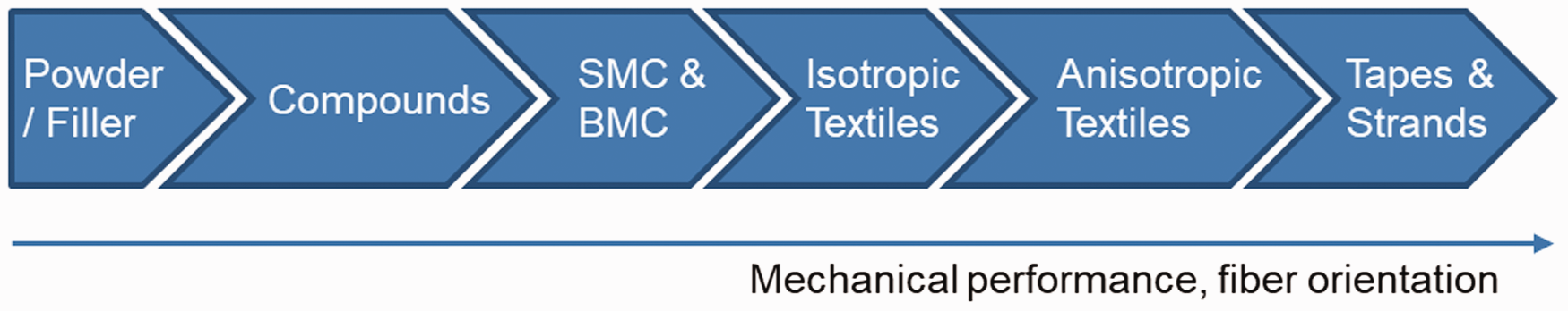
Using milled rCF as powder or filler materials defines the lower end of the recycling potential.7,8 The focus here is to increase rigidity and tensile strength of thermoplastics. Closely related to this process, rCF are used as short fiber reinforcement in thermoplastic compounds for injection molding processes, 9 for example in combination with polyphenylene sulfide matrix.9,10 Industrial solutions for rCF compounds are provided by, e.g. Toho Tenax 11 and WIPAG. 12 In the field of pressing processes, SFP for thermoset compounds such as sheet molding compounds (SMC) and the related bulk molding compounds have been investigated by various authors13–15 in relation with thermosets as matrix. An example for the application of rCF–SMC is the C-pillar of the BMW 7 series as published in 2016. 16
Regarding textile SFP, not only woven structures and non-crimp fabrics (NCF), but also the mechanically inferior—but less complex to manufacture—isotropic textiles have to be mentioned. Non-wovens, veils, etc., usually found in combination with thermoplastic matrices, have been subject to recent research by mainly European scientists with different research foci, such as the manufacturing itself,17–20 the investigation of mechanical properties for (multiphase) rCF isotropic textiles, 21 and for special purposes as for example electro-magnetic interference shielding 22 or as heating elements. 23 A patent for the manufacturing of isotropic textiles with tailored material properties has been filed by Geiger. 24 Car manufacturers investigate the potential of non-wovens for in-house recycling routes. 25 Isotropic textiles also mark the high-end solution for rCF SFP with random fiber orientation. In the sector of SFP with aligned fibers, anisotropic textiles (oriented veils, oriented non-wovens, wovens, NCF), tapes, and strand-built SFP can be distinguished. For the manufacturing of aligned rCF veils, the wet-laying process is suitable for low area weights.26,27 For aligned rCF non-wovens, carding processes provide a good relation between area weight (20–200 g/m 2 ) and output rate.27,28 Regarding industrial relevance, first aligned non-wovens are commercially available. 29
In the case of wovens and NCF, respectively, yarns have to be manufactured as intermediate product first.30–34 Staple fiber organic sheets made of rCF have been developed based on rCF yarns, providing comparable but not yet equal material properties as virgin CF organic sheets. 35 In Longana et al., 36 the high performance discontinuous fiber process was applied in order to align rCF for the production of epoxy-based prepregs which also provide close to vCF values in terms of mechanical performance. By considering a second recycling loop, values significantly decreased by ∼20%. 36 To prevent fibers from losing their orientation in the second life-cycle application, studies have been conducted to maintain the original woven structure of CF SFPs. In Meredith et al., 37 for example, research was conducted by recycling out-of-life prepreg rolls by pyrolysis without damaging the original woven structure. It is questionable how relevant the work in Meredith et al. 37 is for the advancement of CF recycling, since a proper stock management would avoid the occurrence of the treated out-of-life prepregs in the first place.
In contrast to wovens and NCF of aligned rCF staple fibers, tapes and strands made of rCF are suitable to be placed according to the load paths in parts. This could lead to an optimal exploitation of rCF. In Hofmann et al., 38 rCF strands were developed which contain either 100% rCF or a thermoplastic fiber fraction. In Ishikawa et al., 39 the development of thin rCF tapes is reported which show superior mechanical properties. In Taketa et al., 40 research was conducted to improve so-called unidirectionally arrayed chopped strands by modifying slit patterns. Although virgin CFs of the type Toray T700S were used with an epoxy resin matrix in this work, the basic principle of staple fiber tapes could be adopted to rCF. Slitting of virgin material would be unnecessary, the staple fiber character of rCF would even support the SFP structure.
In general, it can be stated that the research in rCF applications and manufacturing processes is accelerating and constantly increasing the potential to bring rCF in a second life cycle. But the developments in different manufacturing processes also show that only those routes can lead to a true recycling, where the fiber lengths are maintained and fibers are aligned during the process. Sufficient fiber lengths and the alignment of fibers in load direction are crucial to mechanical performance. In Gillet et al., 41 the influence of fiber lengths and alignment on mechanical properties was investigated. Although the authors did not use rCF, but virgin fibers with sizing, a clear influence of both – the fiber length and the alignment – on mechanical properties could be observed. Unidirectional (UD) tapes made of CF (type Toray T300) and fiber volume content (FVC) of 40% had been tested. The tensile strength decreased by 8% for realigned fibers of 100 mm length and by 28% for realigned fibers of 50 mm length, compared to continuous, but realigned fiber. The tensile modulus was not significantly affected, although for 50 mm CF, the values showed a higher scatter. Regarding the alignment, shorter fiber lengths combined with an off-axis angle of 15% severed the decrease in strength. In general, an off-axis angle of 15% led to a maximum decrease in tensile strength of 15% (50 mm CF length). 41
In the latter case, a decrease of 15% was rather a positive result compared to AVK. 42 In this calculated case for glass fiber composite with epoxy as matrix, a 15% off-axis angle leads to a decrease in strength of about 50%.
Carding processes are suitable to align up to 90% of rCF, although it leads to a broad fiber length distribution from under 1 mm up to the original input length. Usually this fiber distribution is corresponding to a Gaussian curve. The average fiber length is depending on process management and topic of current research.30,31,34 The carding process needs to be adopted for the treatment of CF, but it shows a high potential for aligned rCF SFPs in sufficient output rates while preserving the fiber length the best possible.
It can be concluded that when using rCF material, the most challenging points are to prevent the following:
Misalignment of fibers: As mentioned above, already a small amount of misalignment of the fibers away from the ideal 0°-direction leads to a significant decrease of strength and stiffness (Figure 2). Lack of fiber sizing: The fiber sizing is operating as a coupling agent for fiber–matrix adhesion and is therefore crucial to load transmission in composites. But most recycling processes remove the sizing from fibers (e.g. pyrolysis). Hence, either new sizing has to be applied to rCF, or a loss in mechanical properties has to be accepted. Damage of fibers: Any damage of fibers occurring at any point of the recycling process, for example due to local notches or kinks is a possible source for crack initiation. Fiber length: A minimum fiber length of at least 3 mm must be preserved by processing rCF according to Flemming et al.
43
Literature also indicates that a further increase of strength and stiffness of composites can be achieved by preserving fiber lengths beyond 50 mm.
32
In contrast, insufficient fiber lengths severely affect the mechanical performance of the composite and thus disadvantage the recycling. Composites reinforced with short rCF are considered to be a down-cycling of the material.
Objective
The present work aimed at the development of a recycling process for long rCF (LrCF), where fiber length is preserved and load-related fiber orientation is possible.
Following the presented state of the art, an expedient approach for best use of the properties of rCF is processing via automated tape laying (ATL). The specific reasons are:
No need for textile processes such as weaving or manufacturing of a non-crimp fabric, these processes are costly and bear the danger of further damaging of the fiber; High flexibility, new fibers can be substituted and combined with recycled fibers at any ratio; All benefits of ATL such as load-related placement of fibers with best use of anisotropy.
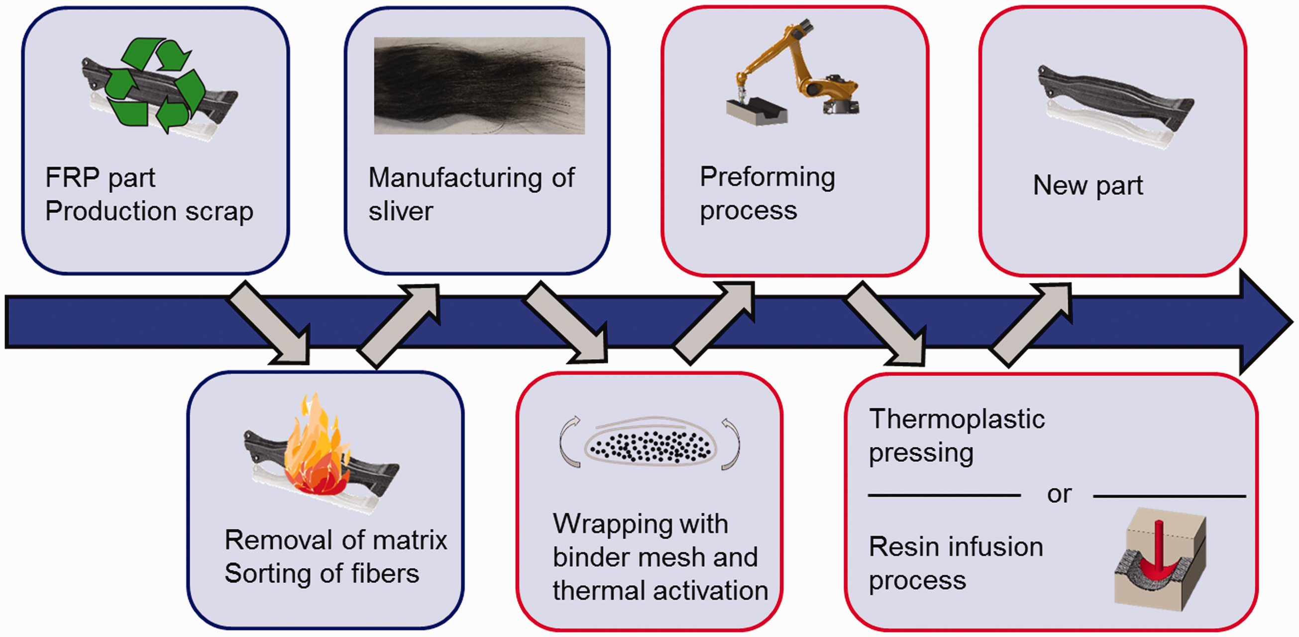
The starting point for the present work was so-called slivers, which are long bundles of fibers resulting from a carding and drawing process that has been applied to fiber scrap (see Figure 3). The main focus of this work was on the development of a binder mesh application rig, which processes the sliver to a binder tape, processable in an ATL process, and a subsequent composite manufacturing process.
Calculated relation between off-axis angle and loss in strength (blue) and stiffness (red).
42
Depiction of conducted process chain.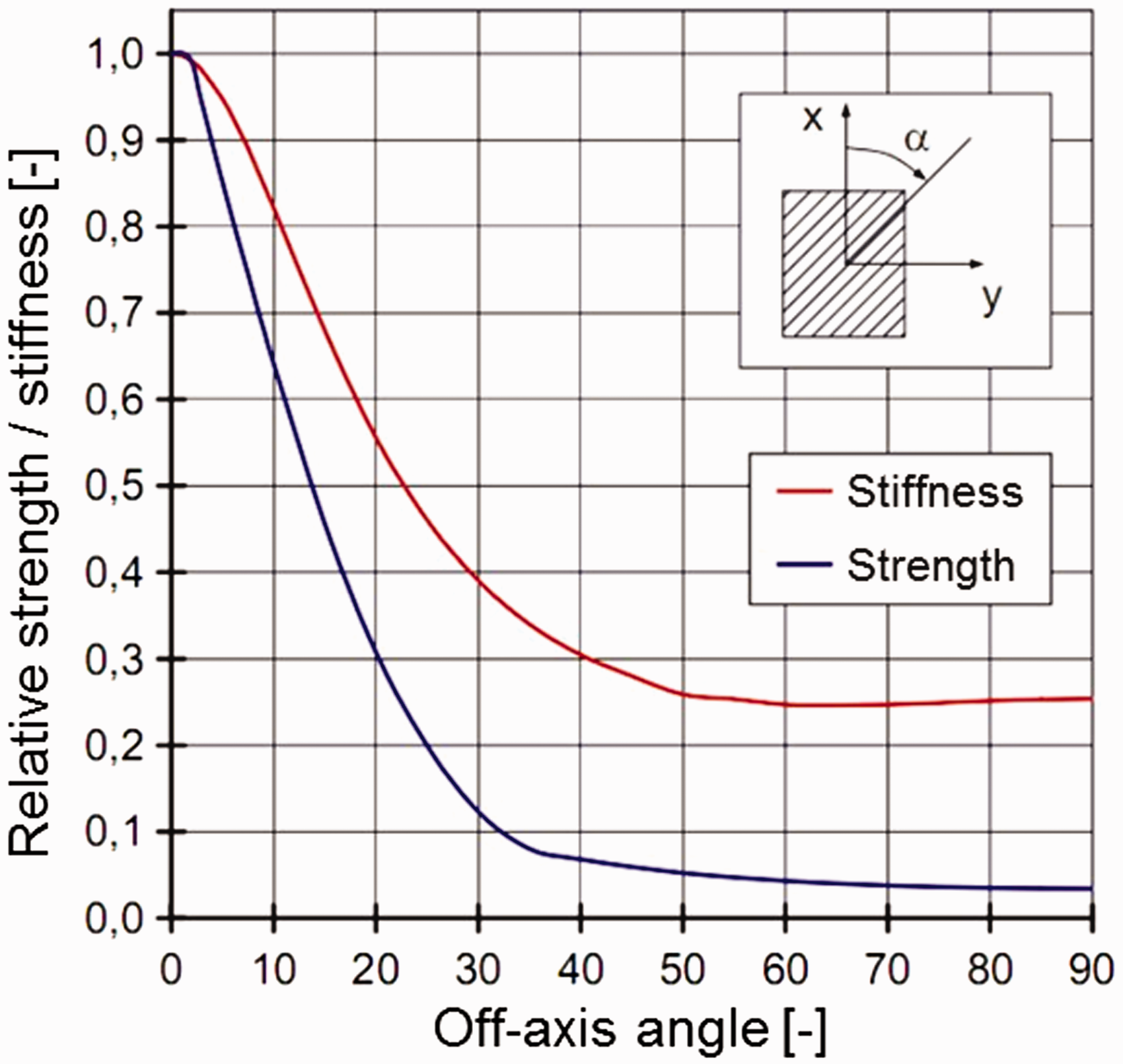
This paper presents the developments on the binder mesh process including a validation consisting of laminate manufacturing via hot pressing and resin transfer molding, respectively.
Materials and methods
In the following, input materials as well as used machinery and processes for laminate manufacturing are described.
Sliver material
The basis for the considered process is a sliver material, which is a strand of limited length fibers mostly aligned in length direction of the product as can be seen in Figure 4.
Sliver material, bending due to gravity shows low bending stiffness.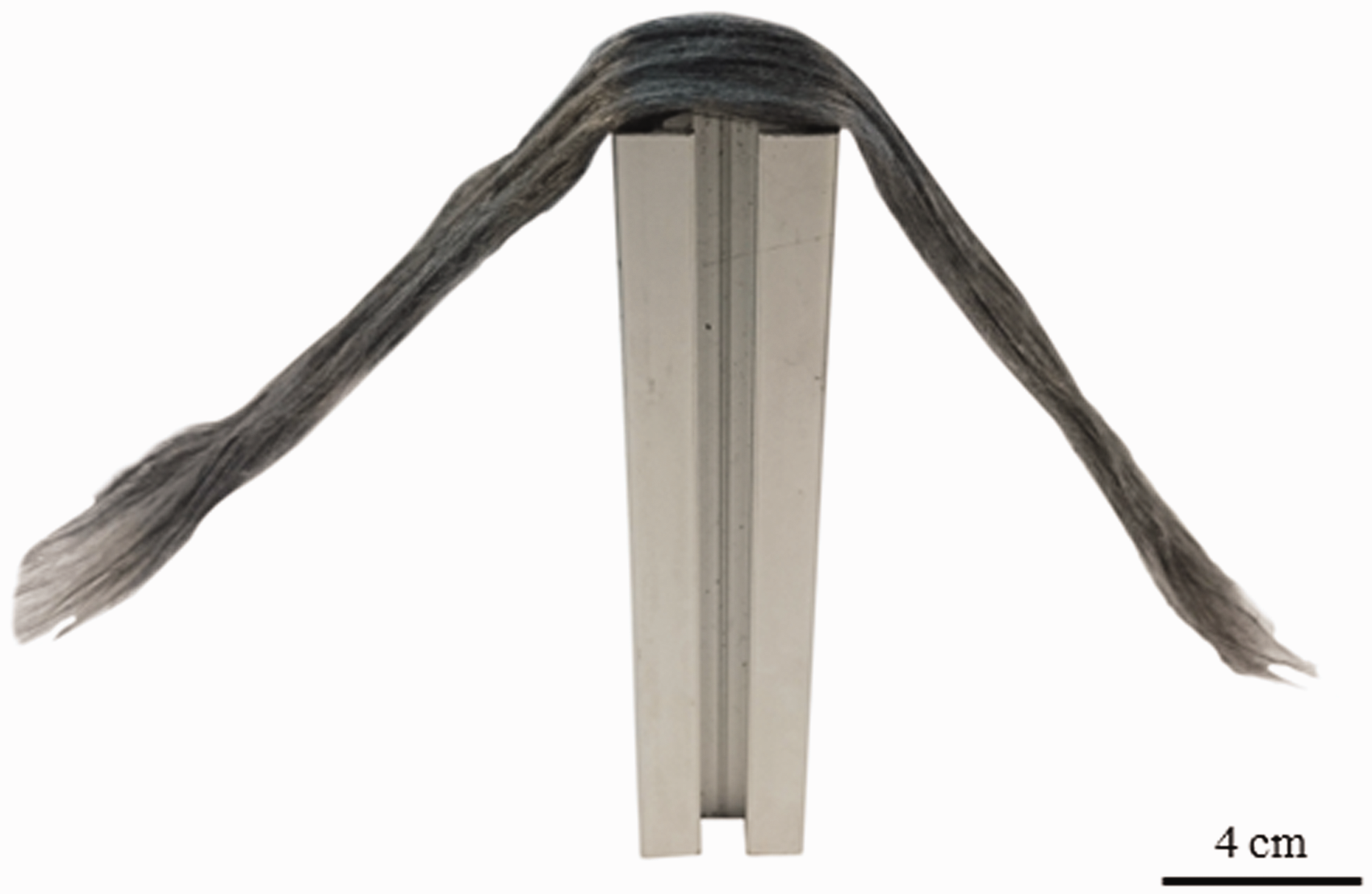
The sliver is the result of a carding process performed by ELG (ELG Carbon Fibre Ltd., Coseley, UK) 1 with subsequent drawing process by DITF 2 (Deutsche Institute für Textil- und Faserforschung Denkendorf). The input material for the carding process was CF material which was regained from pyrolyzed virgin CF with a length of 150 mm. During the carding process, the fiber balls resulting from Pyrolysis are untangled and the sliver is pre-formed. The drawing process is required for optimization of fiber alignment and material homogeneity.
During these processes, auxiliary thermoplastic fibers like PA6 can be added for better processing with less fiber shortening. These can also be used as matrix material as will be shown below.
The sliver material used in this work had a length weight of ≈4 g/m. Due to the lack of stabilizing structure or auxiliary material, the sliver shows only little cohesion that is achieved by friction between single fibers. Figure 5 shows a basic testing setup for a tensile test and the force displacement curve for five samples at a testing speed of 50 mm/min. The average maximum measured force was 4.52 N at an average elongation of 13.5%.
Tensile examination of sliver material. Left: Testing rig, Right: Force-Displacement curve shows constant sliding of staple fibers during tensile test.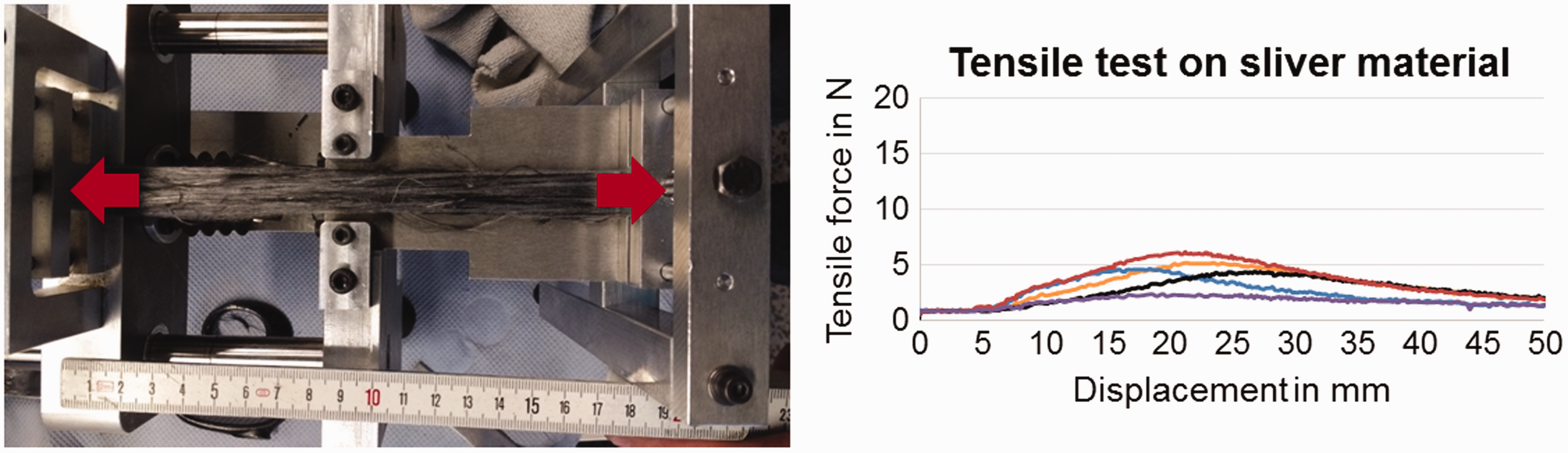
During this tensile test, it can be observed that fibers slide slowly on each other without distinct force peaks, thus a certain amount of stretching can be conducted during material processing. With tensile force applied on the sliver, it can be seen by visual inspection that the fibers tend to be better aligned than in unstressed condition. Still, the measured maximum forces strongly limit the processability of the material in further process steps.
For this reason, the application of a binder material is necessary to ensure sufficient cohesion for automated processing of the material.
One severe drawback of recycled material is the possible variation in weight per length and the resulting inhomogeneities during processing. Besides possible rupture of the material due to local weaknesses, also jamming of the machines due to local accumulations can occur. Furthermore, variations of weight per length impose problems during later steps as the produced preforms suffer from variations of local thickness. For the material processes in this work, local variations in weight per length of 50% have been observed.
Binder mesh
For manufacturing the binder tape, a copolyamide adhesive web binder (Spunfab PA1807) has been used. It is intended for use in manufacturing of composite materials. The melting range specified by the manufacturer is 120–135℃. During binder application, it has been used with a grammage of 10 g/m 2 at a width of 75 mm. Together with the sliver length weight of 4 g/m, the resulting binder weight fraction is 15%.
Part manufacturing for validation tests
To validate the developed binder manufacturing process, two possible process routes for manufacturing of a finished laminate were considered: a thermoplastic and a thermoset route. Both preforms are manufactured out of the novel binder mesh tapes via a dry fiber placement process (Figure 6). Subsequently, the two alternative routes were followed as detailed in the following. For binder tape manufacturing, binder mesh has been added in both routes.
Dry fiber lay-up process with industrial robot.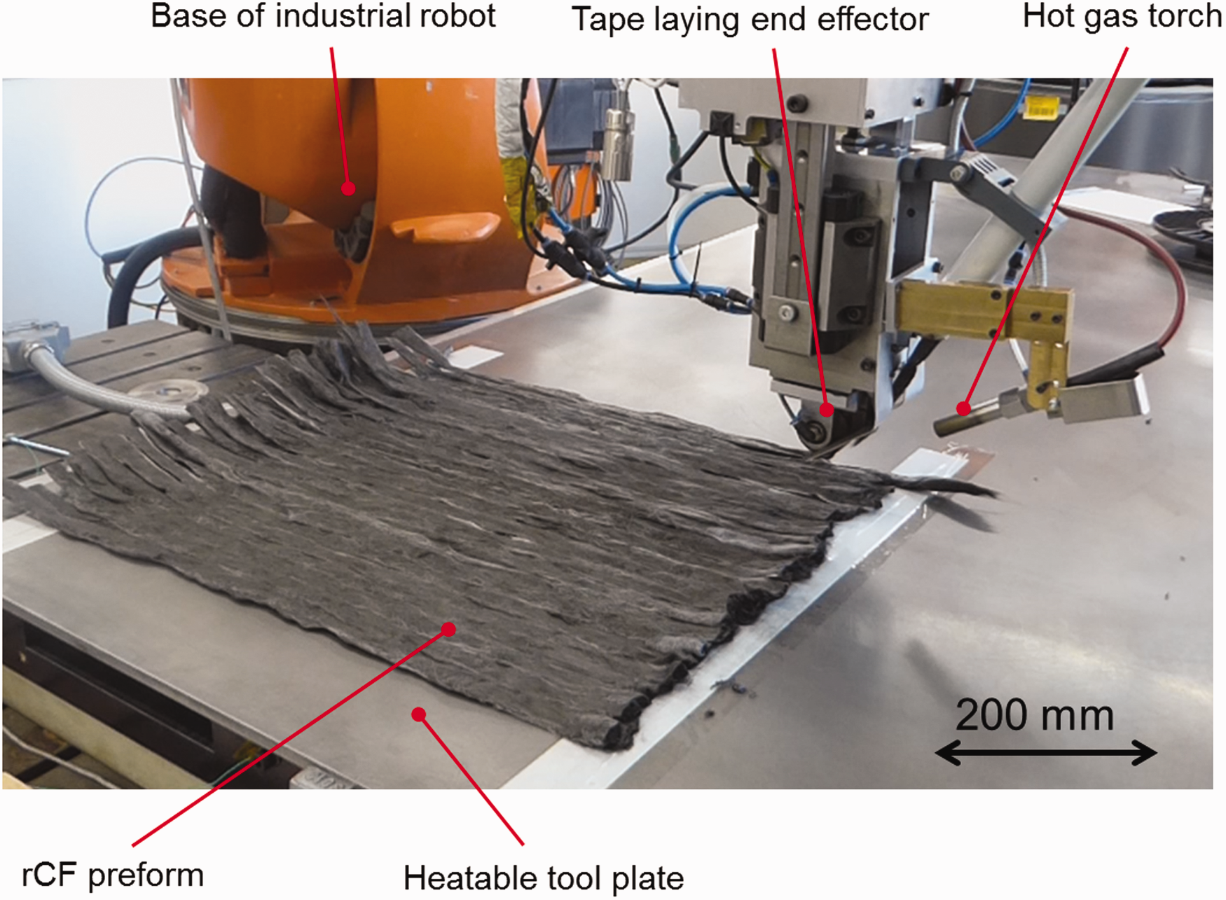
Thermoplastic route
As already mentioned, auxiliary fibers like PA6 might be added during sliver manufacturing. Depending on the amount, it can be expedient to follow a thermoplastic process route. This means that the amount of auxiliary fibers added is sufficient to achieve complete impregnation of the finished part at 50% FVC. Due to not perfectly aligned fibers, higher intended FVCs could possibly lead to local voids due to shortage of matrix. After manufacturing the preform, it can subsequently be consolidated to the finished laminate using a pressing process that can either produce a flat plate or form the preform into net shape.
For the validation tests, preforms with pure UD lay-up were manufactured by ATL. To reach a FVC of 50% at the thickness of 2 mm during pressing, a total sliver mass of 2943 g/m 2 was used.
The preforms were then pressed with 20 bar at 250℃ for 30 min and following cooled down again. To ensure that the desired height is reached and to prevent excessive bleed out through the flashing faces, PA6 organic sheets were inserted into the mold next to the preform (Figure 7).
Plate after thermoplastic pressing with visible organic sheets at edges for height adjustment.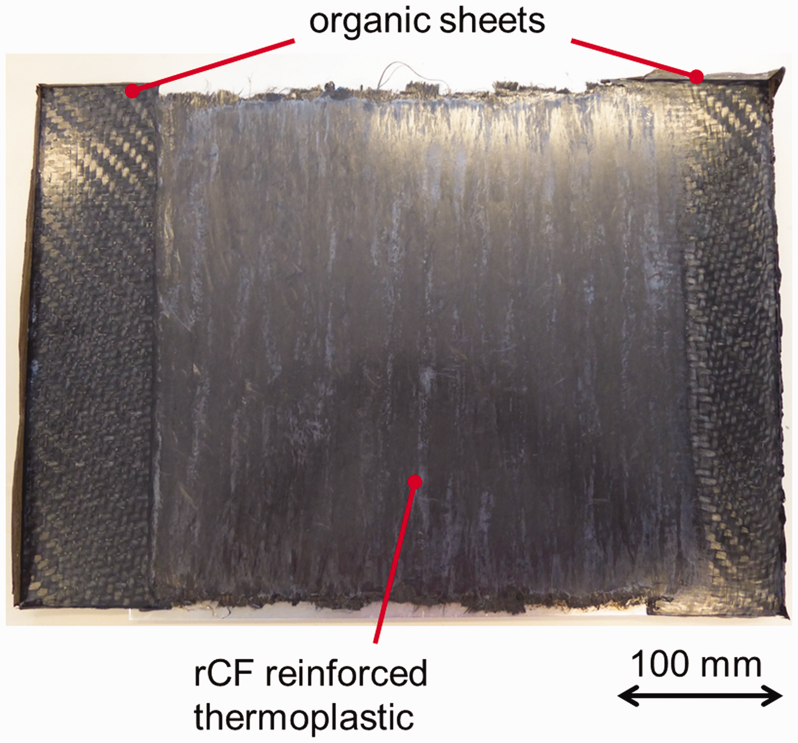
Thermoset route
The preform resulting from the dry fiber placement is porous and can also be processed in a resin transfer molding (RTM) process. During RTM, the porous preform is impregnated with a thermoset resin system in a closed tool. For this process chain, the amount of auxiliary thermoplastic fibers added during sliver manufacturing is critical. This has different reasons:
The adhesion between the thermoplastic fibers and the surrounding thermoset matrix might be deficient and cause reduced mechanical properties compared to a pure thermoset matrix; In fiber reinforced polymer composites, complete impregnation of the fibers is usually required. However, the presence of thermoplastic fibers reduces the available space within the composite for impregnation of CF, thus the achievable FVC is reduced.
Despite possible positive toughening effects on the brittle thermoset matrix that could be caused by the thermoplastic fibers, it has been decided that the effects discussed could probably not be distinguished from the effects to be examined.44,45 For this reason, in the thermoset route, no thermoplastic fibers were used.
For the validation tests, preforms with pure UD lay-up were manufactured by ATL. To reach a FVC of 50% at the thickness of 2 mm during pressing, a fiber mass of this preform (not containing auxiliary PA6 fibers) of 1615 g/m 2 was used.
As mentioned in “Sliver material” section, variations in the sliver's weight per length also result in variations of preform thickness. Due to this reason, the reachable FVC is limited for preforms with larger thickness variations as local agglomerations lead to blockage of tool closing. In the experiments conducted for this work, FVC was limited to 34% due to this effect for the thermoset plate. For input materials with more homogeneous weight per length, 50% FVC can easily be achieved.
For the injections, an RTM process was used, in which the preform was placed in a closed metal tool and vacuum was applied. The system RIMR 935/RIMH 936 by Huntsman was injected at an overpressure of 4 bar (gradual increase starting from 0 bar over 8 min to impede preform deformation). The tool was pre-heated at 50℃ and vacuum was applied. After filling the cavity (20 min), the temperature was increased to 100℃. Curing time was 3 h. The resulting plates showed good surface quality (Figure 8).
Plate after RTM injection.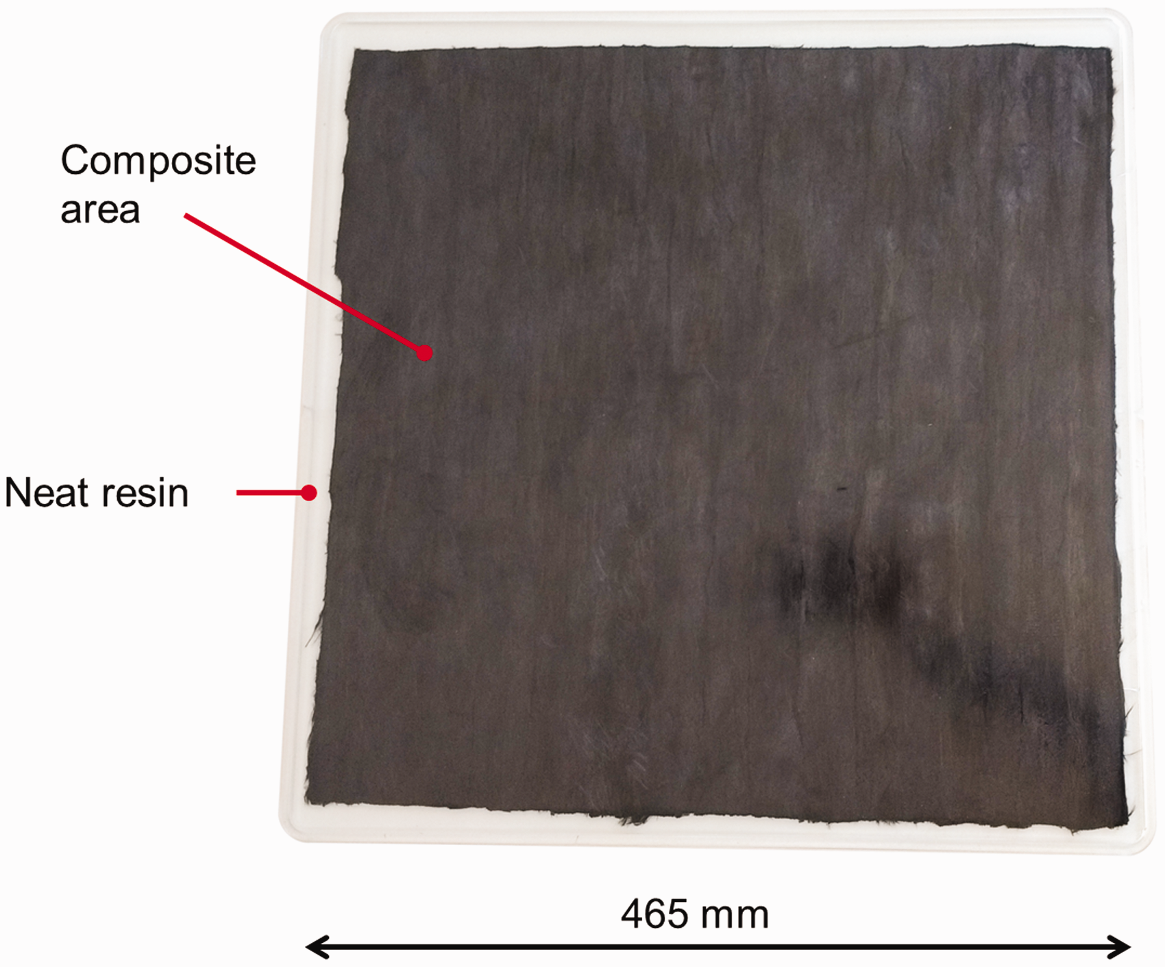
Development of binder application process
As already discussed, the sliver resulting from the carding and drawing process does not possess a sufficient cohesion for further processing in ATL. For this reason, a suitable SFP has to be manufactured. This SFP has to meet the following requirements:
– sufficient tensile stability to be processable in an ATL process; – sufficient cohesion within the roving; – sufficient adhesion between the rovings after lay-up; – limitation of material loss during further processing.
To meet these requirements, different alternatives were evaluated. One common technique used in ATL processes for binder application is the use of powdery binder. However, powder binder needs a large amount of binder material to provide a sufficient cohesion of the SFP.
The second alternative, which was realized in the end, was to envelop the sliver with a thermoplastic binder mesh material (Figure 9), which can subsequently be molten and pressed on the sliver to attach it. This patented procedure has been adapted to a lab-scale binder application machine that is presented here.
46
An overview of the machine can be seen in Figure 10.
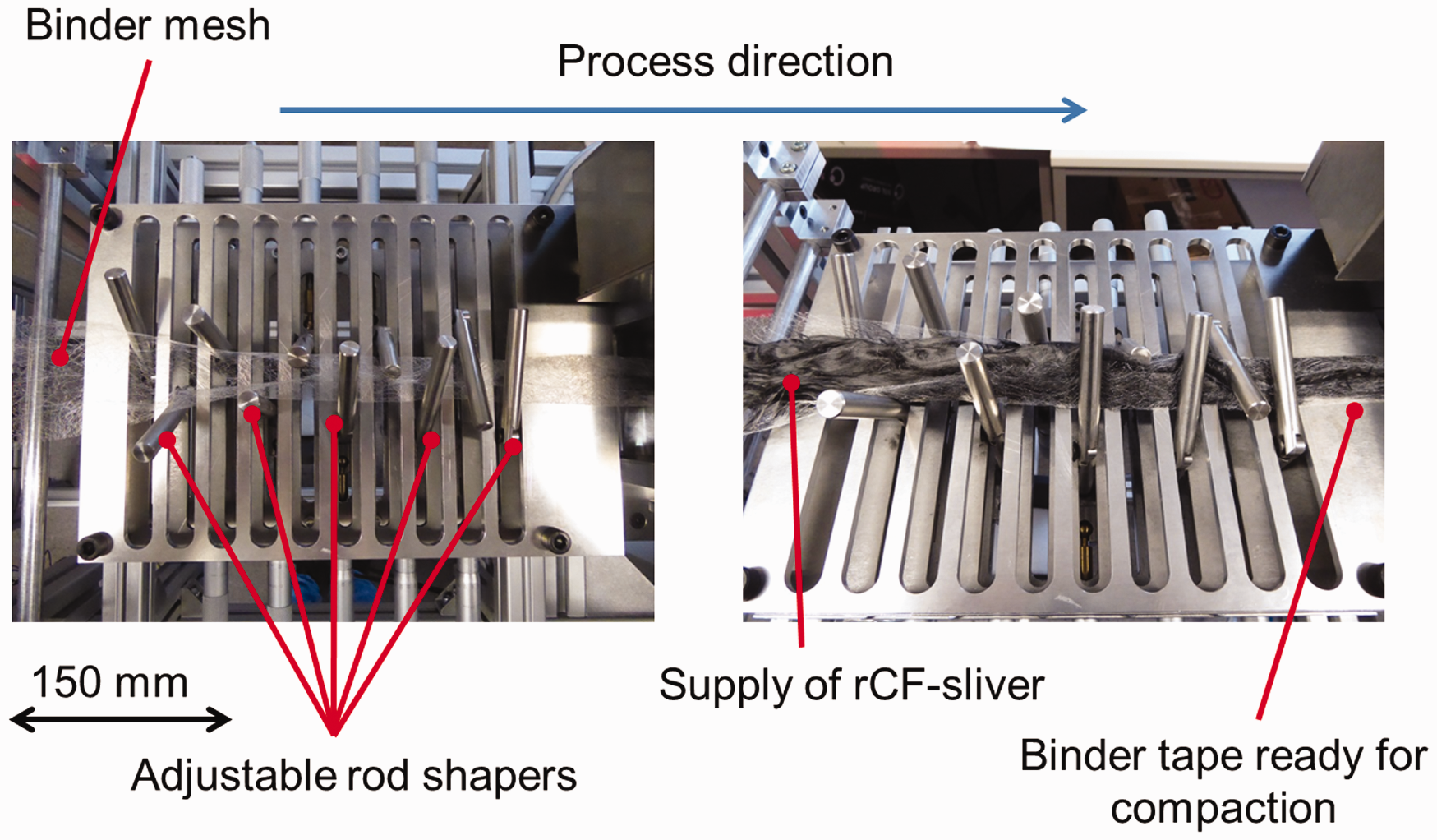
Principle of binder mesh folding. Overview of binder tape manufacturing machine. Detailed view of mesh folding unit.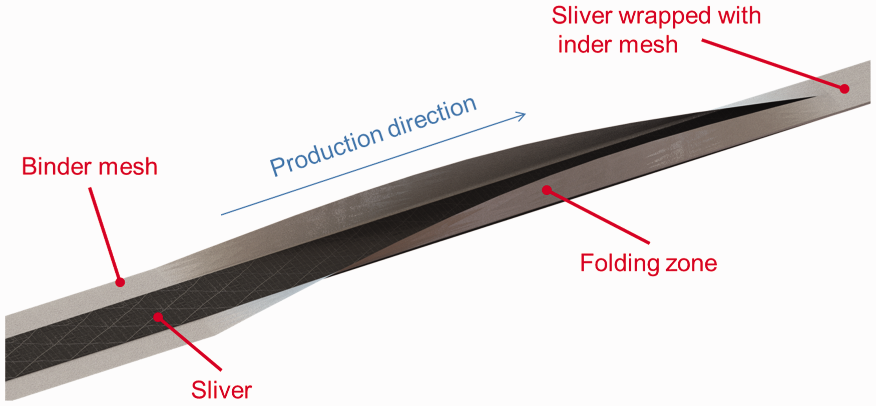
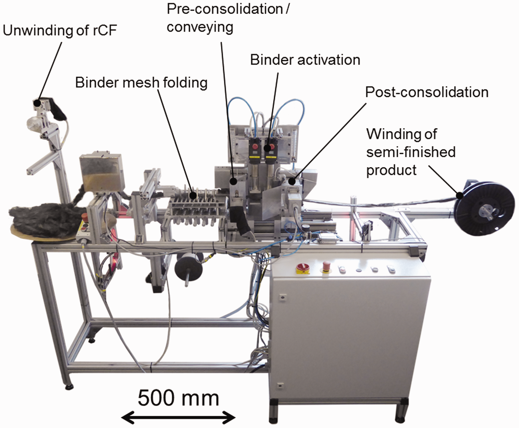
The manufacturing of the SFP, the binder tape, out of the sliver, several process steps have to be conducted subsequently. In the first step, the delivered sliver material has to be conveyed. If the material is already on a spool, it has to be unwound. For controlled unwinding speed, certain material sag is allowed and measured using light barriers. The unwinding speed is then adjusted for constant material sag.
The binder mesh material is continuously supplied from below, and the two material streams are then merged. In a folding unit (Figure 11), rod shapers, adjustable in both position and angle, fold the binder mesh around the sliver. Due to the adjustability, a large variety of input materials with various length weights (sliver) and areal weights (mesh) can be processed.
When the sliver is completely surrounded by the mesh material, the compound is pre-compacted by a propelled pair of rolls with adjustable pressure. In a heating unit, two hot air fans with adjustable temperature and air diffusors heat-up the compound in order to allow a slight melting of the binder material. In a subsequent consolidation step, the binder tape is fixed and cooled by another propelled pair of rolls with adjustable pressure. For enhancement of fiber orientation, a speed difference between the pre-consolidation and final consolidation can be set. The stretched state of the fibers under tension can be frozen with the binder mesh. An overview of the binder tape fixation set-up can be seen in Figure 12.
Tape fixation unit with pre-compaction, heating, and post-compaction.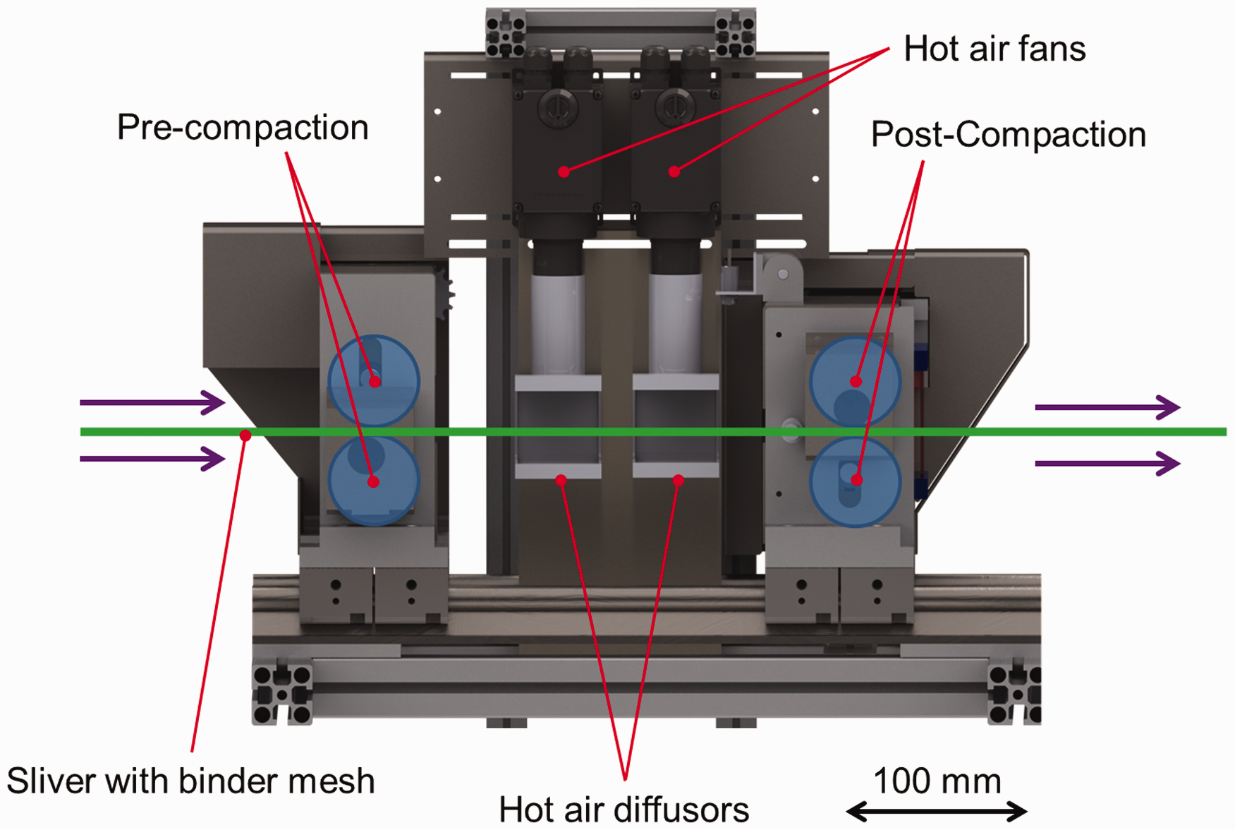
After final consolidation for cooling and compaction, the material can be wound up on a spool for transport to the subsequent automated lay-up step. As the required rotational speed of the spool varies with the increasing diameter of the material on the spool, either sag control with light barriers or tension-controlled spooling can be used.
In conclusion, a very flexible process and machinery for binder mesh application has been developed. Length weights from 3 up to 20 g/m can be processed at a speed up to 20 m/min. A future scale-up to faster process speeds and higher length weights seems expedient and feasible.
Mechanical testing and plate characterization
The properties of the plates after thermoplastic pressing or RTM respectively have been tested using the following methods:
Microsections of the plates to determine impregnation quality and FVC (three randomly chosen spots per plate, not from edge areas for statistical coverage). FVC was additionally verified by 10 thermal gravimetric analyzed per plate; Tensile testing according to DIN EN ISO 527-5 with sample size 250 × 15 × 2 mm3 and a testing speed of 2 mm/min in fiber (process) direction and 90° to fiber direction, at least five samples with valid fracture per plate, not using edge areas (20 mm from the edge); Three-point bending tests according to DIN EN ISO 178 with sample size 80 × 25 × 2 mm3, a testing speed of 2 mm/min and a supporting width of 32 mm, at least five samples per plate, not using edge areas; Scanning electron microscopy (SEM) analysis of fracture surfaces from mechanical testing.
Validation tests
To prove the applicability of the intended process chain, all steps starting from recycled fibers up to a finished laminate have been conducted. For this purpose, all process steps have been optimized and scrutinized for possible problems that might occur at larger scale production.
Plate quality
To examine the impregnation quality of the plates, microscopical examinations of microsections have been conducted for both, thermoplastic and thermoset plates. It can be stated that the plates possess a high impregnation quality and a low void content (<1%) for both cases. Still, it can be seen that in both cases, fiber distribution is very uneven due to local fiber agglomerations and areas with low FVC contents. Regarding mechanical properties, these inhomogeneities could possibly be disadvantageous due to local weakening of the laminate.
This is shown for the thermoplastic plate by a representative clipping in Figure 13. The average measured FVC for the thermoplastic plates is 50%.
Microsection of plate produced in thermoplastic pressing with PA6 auxiliary fibers.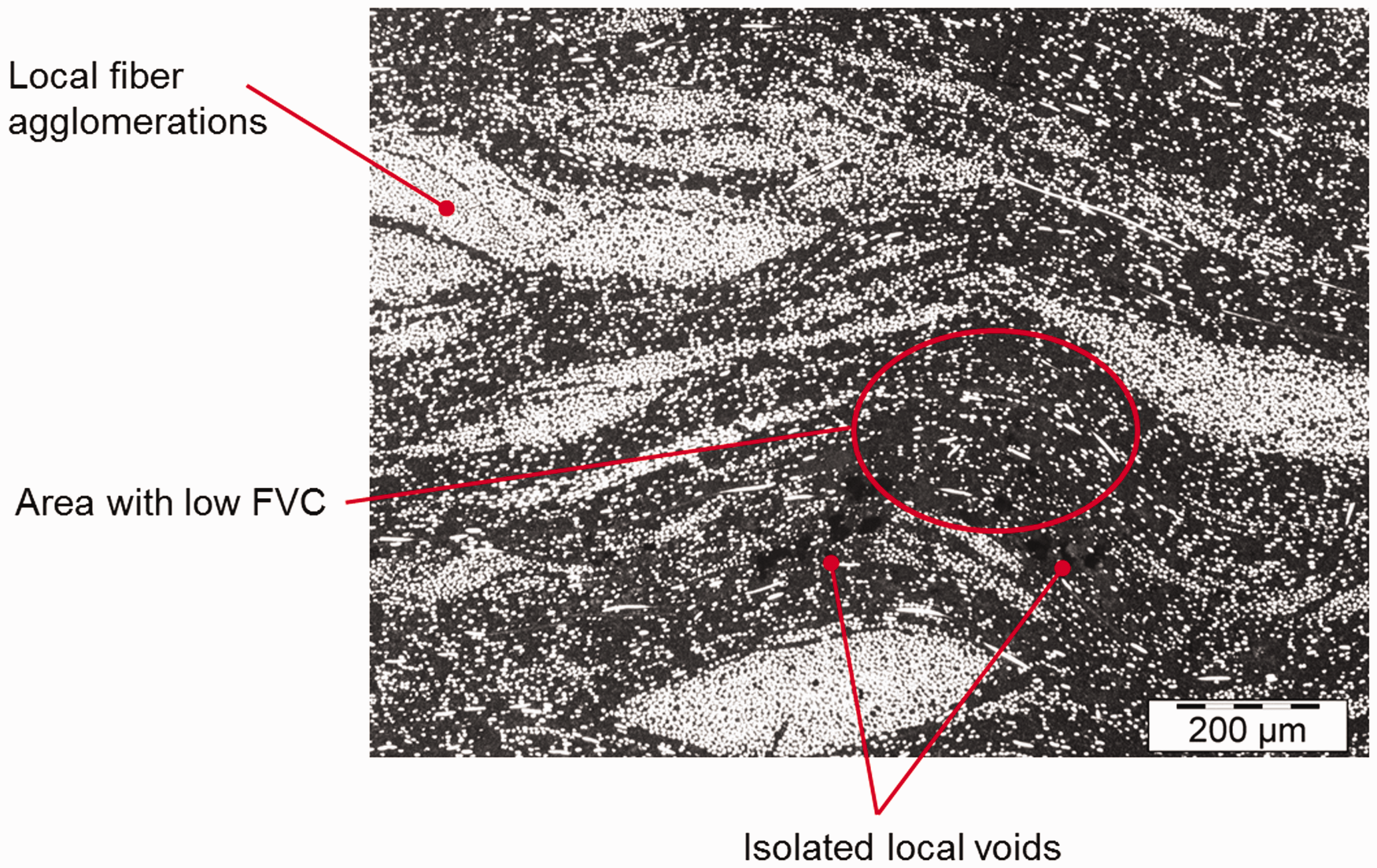
A representative overview and clipping from microsections of the thermoset plate is shown in Figure 14. The average measured for the thermoset plates FVC is 34%. A higher FVC was not feasible due to local agglomerations.
Local clipping of microsection of thermoset plate produced in RTM process.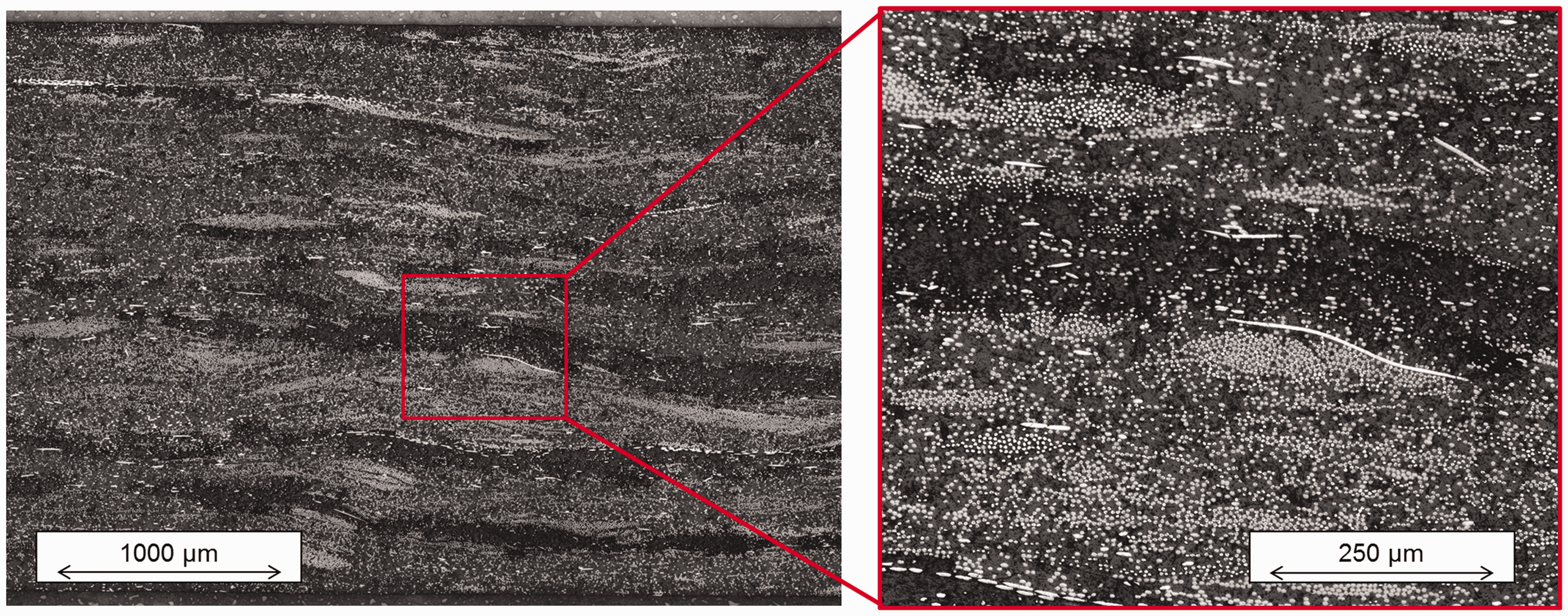
Mechanical testing
This subsection describes the results of mechanical testing done with the manufactured laminates. Tensile properties in 0° and 90° direction as well as bending properties will be assessed with respect to reference materials as well as commercially available rCF materials.
Tensile testing in process direction (0°)
In the results of 0° tensile tests (Figure 15), it can be seen that tensile strength is reduced to less than 25% for the thermoplastic plate compared to a plate manufactured by dry fiber placement with virgin fibers.
47
For the plates with recycled fibers, it was observed by visual inspection (Figure 16, left) that a large amount of fibers is pulled-out of the matrix on the fracture surface. The fibers seem dry and do not show any residuals of the PA6 matrix. This could be one possible reason for this significant reduction of strength compared to a new fiber, as it indicates a very deficient fiber/matrix adhesion. When regarding modulus, the reduction is about 50%. As discussed above, the modulus is mainly influenced by fiber orientation, whereby the lack of sizing has a minor influence on measured modulus. Furthermore, fiber orientation offset has a larger influence on measured modulus.
Results of tensile testing in fiber direction and comparison with virgin fiber (DFP preforming, 50% FVC, epoxy matrix) and commercially available rCF-mat.
48
Comparison of fracture surface by visual inspection between thermoplastic PA6 matrix (left) and thermoset EP matrix (right). Comparison of fracture surfaces in SEM.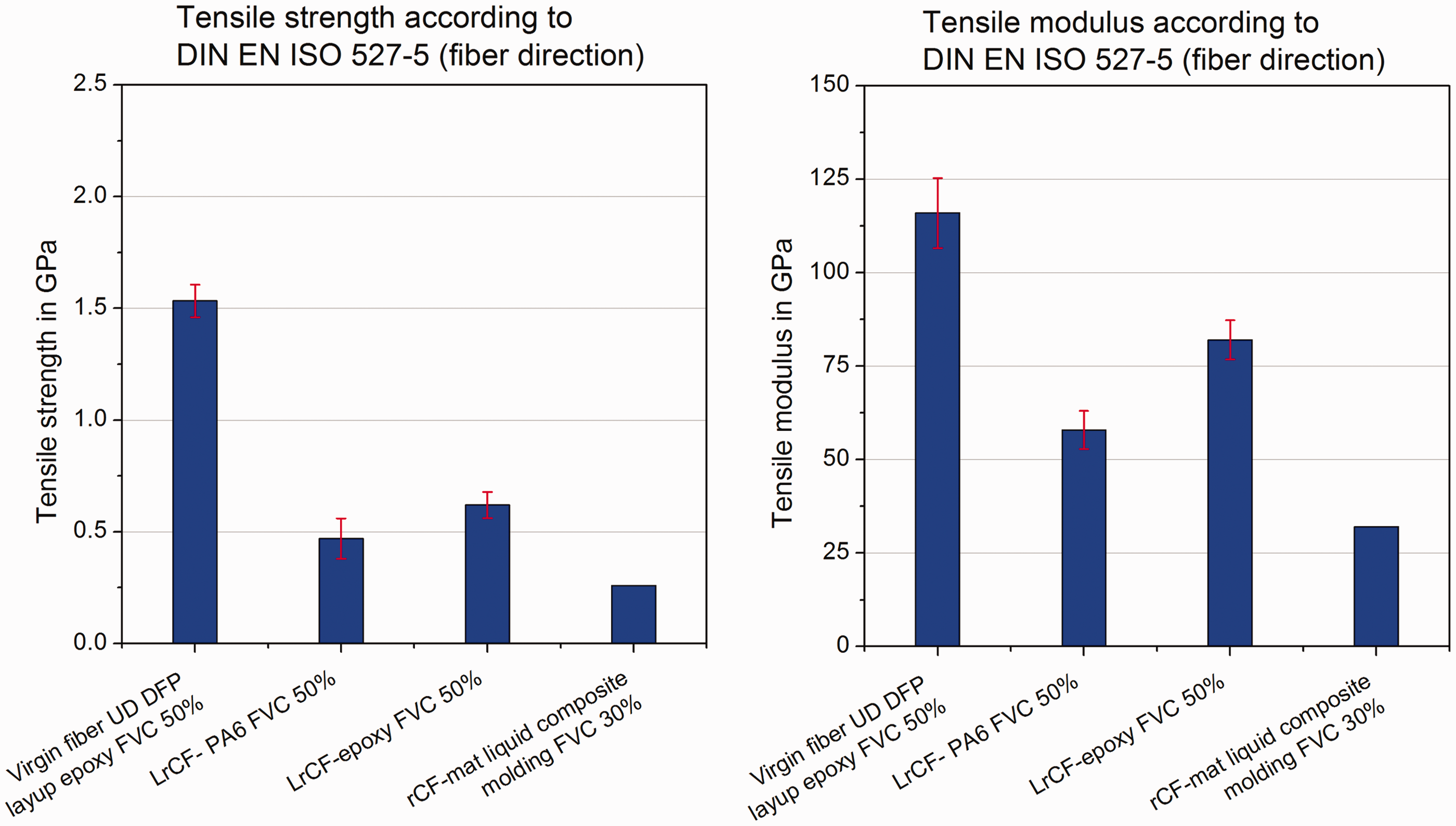
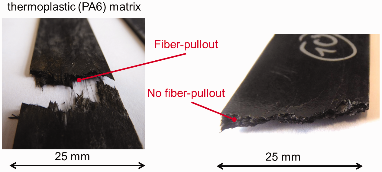
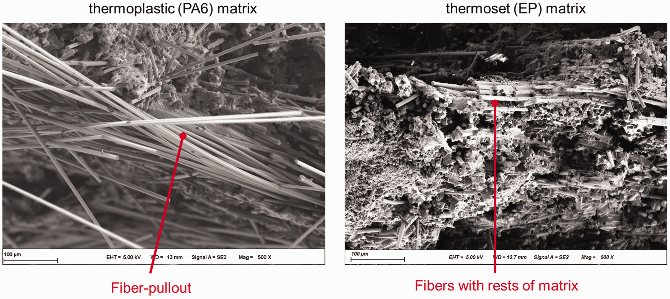
For the thermoset plate, only a fiber volume of 34% was reached as discussed above. For comparison reasons, the values were recalculated to 50% for the 0° tensile test by cross-multiplication. Better fiber alignment has been reached during the binder application compared to thermoplastic plate, possibly due to the different fiber sliding behavior without auxiliary thermoplastic fibers. This can especially be seen in the achieved modulus. Strength is higher than for the thermoplastic plate as well, and this behavior can be explained by better fiber–matrix cohesion observed in visual inspection and SEM (Figure 17) due to the better bonding behavior of epoxy matrix compared to PA6. Hence, thorough attention has to be paid when choosing an appropriate matrix material for rCF.
Compared to commercially available rCF mat material (liquid compression molding at 30% fiber volume fraction 48 ), strength and modulus are significantly higher. It can thus be stated that the efforts aligning the fibers in load direction pay-off by achieving better properties compared to random fiber alignment.
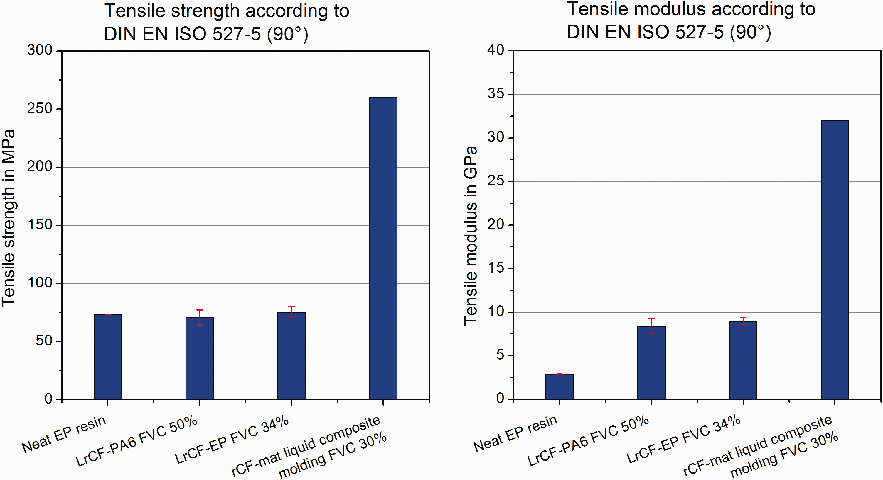
Tensile testing transverse to processing direction (90°)
To determine the properties transverse to process direction, tensile tests have been conducted (Figure 18). The results show a stiffness and strength of about 15% compared to the respective values for 0° direction and thus a high anisotropy of about 1:7 ratio. Despite the lower FVC, the thermoset samples show comparable properties to these of the higher FVC thermoplastic samples. The high anisotropy indicates a high degree of fiber orientation. Compared to a random fiber mat material (virgin fibers), the values are significantly lower in this direction as the random fiber mat material is transversely isotropic. Compared to the unreinforced EP resin, strength is similar while a significant reinforcement can be observed in modulus. This is due to a certain amount of fibers not oriented in 90° direction.
Results of mechanical testing transverse to fiber direction (90°) and comparison commercially available rCF-mat.
48
3-point bending tests
To determine the bending properties of the material, bending tests have been conducted (Figure 19). For the bending properties, the values of the LrCF-thermoset have not been scaled to 50% FVC mathematically as this is only reasonable for 0° tensile tests. Still, comparable properties to those of the thermoplastic at 50% have been achieved. Once again, possible reasons are better fiber alignment for the stiffness and in case of strength the better bonding between fibers and matrix.
Results of bending test and comparison with STFI sliver material.
49
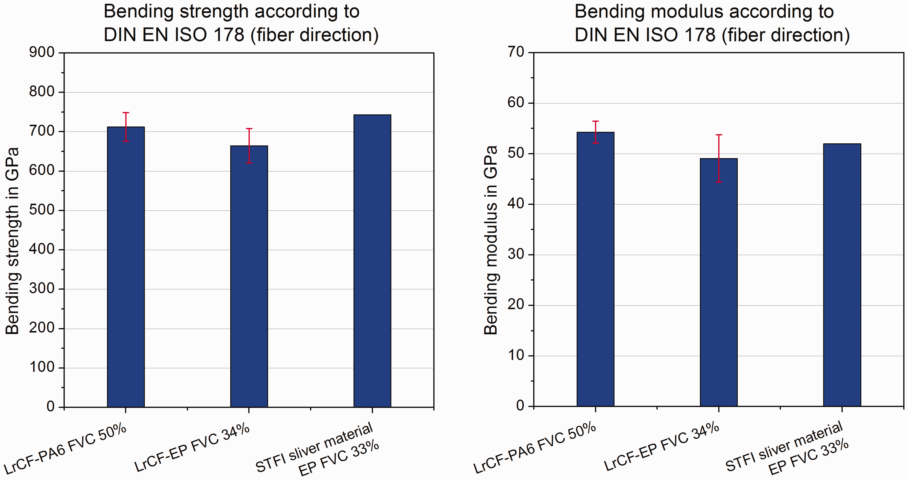
As a reference, the values of a similar sliver material used by STFI 49 have been added which is manufactured by impregnation with an EP-resin as well.
Summary
In the present work, a process chain for the manufacturing of new parts made of LrCF has been suggested. One of the core elements of this process chain is a machine producing LrCF binder tapes out of sliver input material using wrapping with a binder mesh material which has been developed and validated within this study. These binder tapes can be further processed in an ATL process because of the good cohesion and the contained binder material. During the binder application, further stretching of the sliver and freezing this state using binder material have been implemented. The process chain has validated by manufacturing thermoplastic and thermoset plates for material characterization via thermoforming and RTM, respectively. The mechanical characterization revealed that compared to random virgin fiber mat material, fiber properties can be used more effectively by using anisotropy effects. Still, compared to virgin fibers, there is a considerable decrease of properties. Possible reasons are less-than-ideal fiber alignment and deficient fiber–matrix cohesion. The issue of fiber–matrix adhesion has especially been shown for a thermoplastic FRPC.
All in all, the shown process chain bears a large potential for recycling of CF by using more of their potential than common recycling techniques. In future work, fiber alignment has to be further improved as well as homogeneity of sliver input material. Adding a sizing or using dry scrap with sizing on fibers for better fiber–matrix adhesion should be considered in future steps as well. The experiments have been conducted on a lab scale. For further use, adaption of the machinery for industrial-scale application is advisable.
Footnotes
Acknowledgements
The discussed work was funded by Honda R&D Europe (Germany) GmbH.
Declaration of Conflicting Interests
The author(s) declared no potential conflicts of interest with respect to the research, authorship, and/or publication of this article.
Funding
The author(s) disclosed receipt of the following financial support for the research, authorship, and/or publication of this article: Honda R&D Europe (Germany) GmbH.