
Abstract
The valve-controlled cylinder electro-hydraulic position servo system is a nonlinear systems characterized by uncertain parameters and unknown disturbances. These attributes present significant challenges to achieving high-precision motion control of hydraulic cylinders. This study introduces a composite control strategy that merges active disturbance rejection control (ADRC) with integral feedback to further enhance the position tracking accuracy of the system amid unknown load disturbances. The effectiveness of ADRC largely depends on its parameters, which dictate the control precision of the object. However, ADRC typically involves numerous adjustable parameters, necessitating extended tuning periods for new controlled objects. Consequently, this study proposes a universal method for ADRC parameter tuning aimed at minimizing the time required for parameter adjustments. An experimental platform for the valve-controlled hydraulic cylinder position servo system was developed to validate the efficacy of the control strategy and the parameter tuning method. The findings offer valuable insights for enhancing the motion accuracy of electro-hydraulic position servo systems.
Keywords
Introduction
The electro-hydraulic servo system, characterized by its high power density and rapid system response, is extensively utilized in aerospace, the military industry, and engineering machinery. However, the motion accuracy of this system is compromised by numerous uncertain factors,1–3 such as friction between the piston and the hydraulic cylinder’s inner wall, and the variable elastic modulus of the hydraulic oil. These factors can diminish the steady-state accuracy of the hydraulic cylinder piston displacement and induce dynamic jitter, adversely affecting the performance of the main engine. Consequently, it is essential to implement closed-loop control for hydraulic cylinder piston displacement.
Hydraulic cylinder displacement control is categorized into model-based and error-based control methods. Model-based methods, including model reference adaptive control, sliding mode control, and pole placement method, depend on the accuracy of the system model. Inaccuracies in the system model can severely limit the attainable control precision, thereby restricting the practical application of model-based methods. Conversely, error-based control methods, such as proportional-integral-derivative (PID) control and active disturbance rejection control (ADRC), do not require a precise mathematical model and are thus more prevalent in engineering applications.
ADRC4,5 is developed based on the PID method. Unlike the PID algorithm, ADRC incorporates a tracking differentiator (TD) and an extended state observer (ESO). The TD calculates the differential of the input signal, preventing abrupt changes in the desired trajectory and establishing a foundation for target tracking control. The ESO observes the system’s disturbances, further mitigating the impact of uncertainties on tracking accuracy. Fu and Tan 6 applied ADRC to control unstable systems with time-delay loops. Lixin et al. 7 implemented ADRC for electro-hydraulic proportional servo force control, demonstrating that the ADRC controller enhances tracking accuracy and exhibits stronger anti-interference capabilities. Cheng et al. 8 proposed an extended observer based on system identification, improving disturbance estimation precision and ultimately enhancing ADRC control performance. Zhao and Li 9 designed an ADRC controller for SISO systems with unknown order and relative degrees, deriving ADRC parameters from PID control parameters for rapid tuning. Tian and Gao 10 analyzed ADRC using a frequency domain approach, demonstrating its robustness based on transfer function theory. Zhao et al. 11 proposed an improved ADRC algorithm to address issues related to the braking system control precision and response speed in electric vehicles. Zhang et al. 12 introduced a sensorless ADRC vector control method for regulating permanent magnet synchronous motors, enhancing motor motion accuracy. Jin et al. 13 proposed a control strategy combining a load torque dimensionality reduction observer with ADRC to achieve rapid motor tracking. Xuesong et al. 14 proposed an ADRC strategy with optimized observation deviation to enhance the utilization efficiency of new energy in hybrid energy storage microgrid.
To further enhance the robustness of the control algorithm and reduce the influence of nonlinearity and uncertainty, researchers have proposed hybrid ADRC control methods, such as the combination of ADRC with sliding mode control, and the combination of ADRC with fuzzy control. 15 When combined with sliding mode control, the extended observer can estimate external disturbances and model errors. Sliding mode control only needs to handle the residual small uncertainties and ensure convergence, thereby improving the stability and robustness for the controlled object. When combined with fuzzy control, this can solve the problem of fixed ADRC parameters, which makes it difficult to ensure optimality under all operating conditions. Combining fuzzy reasoning, the bandwidth of the ADRC is adjusted according to the working conditions, enabling the ADRC to be applicable to a wider range and more complex changes in working conditions. Fang et al. 16 suggested replacing PD in ADRC with sliding mode control and verified the effectiveness of the new algorithm through motor speed control. Jie et al. 17 put forward an improved sliding mode ADRC strategy to reduce the transient DC bus voltage fluctuation in the photovoltaic energy storage integrated converter and to accelerate the power response speed. In the conventional ADRC algorithm, only differential and proportional feedback is included, while integral feedback can effectively eliminate steady-state error. Therefore, in this paper, integral feedback is introduced into the framework of ADRC to improve the steady-state tracking accuracy of the hydraulic cylinder.
It can be seen that ADRC control method has extensive applications in fields such as hydraulic transmission, automotive braking, motor control, and new energy. However, the setting of control parameters remains an unsolved problem in the practical application of ADRC. Similar to PID, the parameters in ADRC directly affect the transient performance and steady-state performance of the control result. For different control objects, the parameters of ADRC vary greatly, and it requires on-site repeated debugging to obtain a relatively ideal parameter. Therefore, there is an urgent need for a parameter tuning method that does not rely on personnel’s experience and is more efficient. Currently, The parameter tuning methods for ADRC primarily include three categories: (1) bandwidth-based tuning, 18 (2) tuning based on the similarity control method, (3) tuning based on the approximation of the desired transfer function.
The bandwidth-based tuning method simplifies the multiple control parameters of ADRC into two parameters, namely the controller bandwidth and the observer bandwidth, thereby simplifying the parameter setting process. The controller bandwidth is determined by the closed-loop pole configuration, which determines the response speed of the system. The bandwidth of the observer determines the estimation accuracy and speed of the observer.
The parameter tuning based on the similarity control method is to analyze the connection between ADRC and the similarity methods, and to obtain the control parameters of ADRC by using the parameters of similarity methods. Rong et al. 19 proposed establishing a relationship between the PID transfer function and the ADRC transfer function to derive ADRC control parameters from PID control parameters. Based on Zhou Rong’s work, Han and Tan 20 derived the formula for calculating the ADRC control parameters using the commonly used PID control parameters setting methods. Tan and Fu 21 transformed the ADRC control structure into Internal Mode Control (IMC) and devised an IMC-based method for tuning ADRC parameters. Similar to the PID-based parameter tuning method, this approach is based on IMC.
The method of approximating the desired transfer function involves comparing the ADRC closed-loop transfer function with the desired transfer function, and determining the control parameters based on the equality of corresponding coefficients. Liu et al. 22 proposed the ADRC parameter tuning rule based on the target approximation method for high-order time-delay systems. The parameters of the controller were determined by comparing the closed-loop transfer function of the control algorithm with the expected transfer function. This method uses a single parameter λ to adjust the controller parameters, simplifying the parameter tuning process. But, this method is only applicable to high-order time-delay systems. Tao et al. 23 suggested an ADRC parameter design method based on the Nyquist curve for oscillating systems. This method is mainly applied to oscillatory objects. The controller parameters are determined based on the left asymptote or intersection point of the expected Nyquist curve of the controlled object. The Nyquist curve is essentially the same as the transfer function. Therefore, this method belongs to the approach of approximating the desired transfer function.
Although these methods offer effective approaches for designing ADRC parameters, they each possess certain limitations. For the bandwidth method, the controller bandwidth and the observer bandwidth need to be repeatedly adjusted to obtain relatively appropriate values. This will consume a great deal of time. The parameter tuning based on the similarity control method will require first determining the control parameters of the similar method, but the control parameters of the similar method are usually difficult to determine. The method of approximating the desired transfer function requires the known transfer function of the controlled object. But, for some production equipment, it is often difficult to determine their transfer function. Taking the above considerations, this paper proposes a widely applicable and experiment-based method for setting the control parameters of ADRC.
The main contribution of this paper lies in: (1) proposing a unified method for ADRC parameter tuning based on experimental tests, which enables the parameter tuning process to be efficient and independent of experience; (2) presenting a new control strategy that combines ADRC with integral feedback to enhance system response speed and minimize steady-state error. Experimental results with a valve-controlled hydraulic cylinder position servo system show that this tuning method can significantly shorten parameter tuning time and provide valuable guidance for on-site debugging. The composite control strategy effectively reduces steady-state jitter amplitude.
Valve-controlled cylinder system modeling
The electro-hydraulic position servo system of the valve-controlled cylinder is depicted in Figure 1. This system comprises a constant delivery pump 1, a relief valve 2, a servo valve 3, and a double rod piston hydraulic cylinder 4. The mathematical model is derived from the flow equation of the servo valve, the flow continuity equation of the hydraulic cylinder, and the force balance equation of the piston.
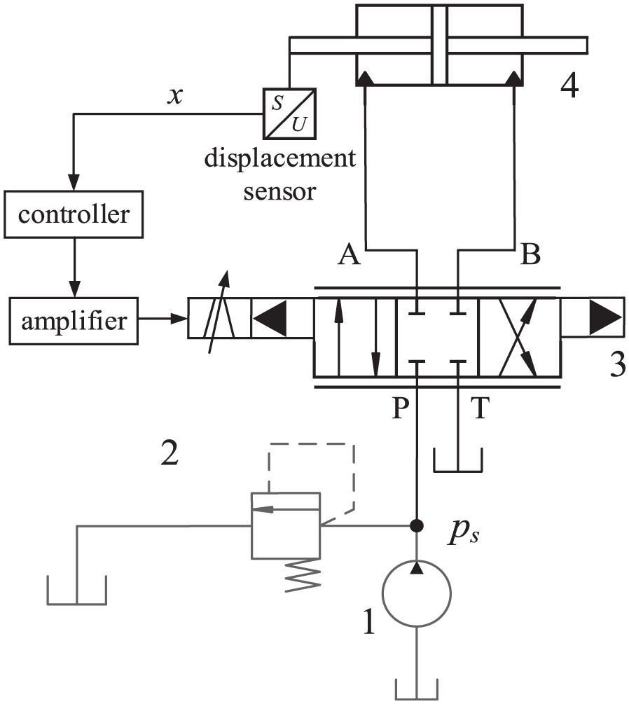
Hydraulic system of the valve-controlled cylinder.
Based on the orifice flow model, the flow equation for the servo valve is given by 21 :
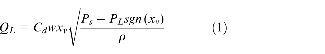
where Q L represents the flow rate through the servo valve; C d is the flow coefficient of the servo valve orifice; w denotes the area gradient of the valve orifice; x v indicates the displacement of the valve spool; P s is the inlet pressure of the servo valve; P L refers to the outlet pressure of the servo valve; ρ is the density of the hydraulic oil.
The continuity equation for the hydraulic cylinder flow is 24 :
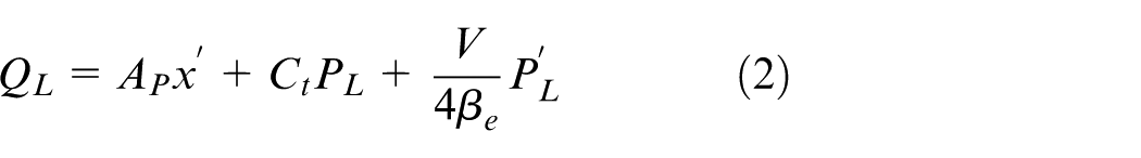
where A P represents the area of the hydraulic cylinder piston; C t denotes the internal leakage coefficient of the hydraulic cylinder; V refers to the volume of the inlet chamber in the hydraulic cylinder; β e is the volumetric modulus of elasticity of oil; x indicates the displacement of the hydraulic cylinder piston.
The force balance equation for the piston of hydraulic cylinder is as follows:

where M t represents the mass of the piston; B P is the viscous damping coefficient of the frictional force between the piston and the cylinder wall; k is the elastic stiffness of the load spring; F L denotes the external load force. F L typically varies during the operation of the hydraulic cylinder and is considered as one of the uncertain variables in this study.
Assuming the servo amplifier functions equivalently as a proportional link and the relationship between the input current of the servo valve and the spool displacement is also approximately proportional, we derive:
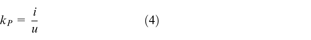
where k p is the amplification factor of the servo amplifier; k sv is the proportionality factor between x v and the input current i; u is the control voltage.
Let the state variables are
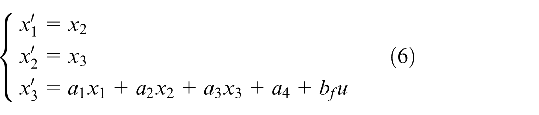

We have:
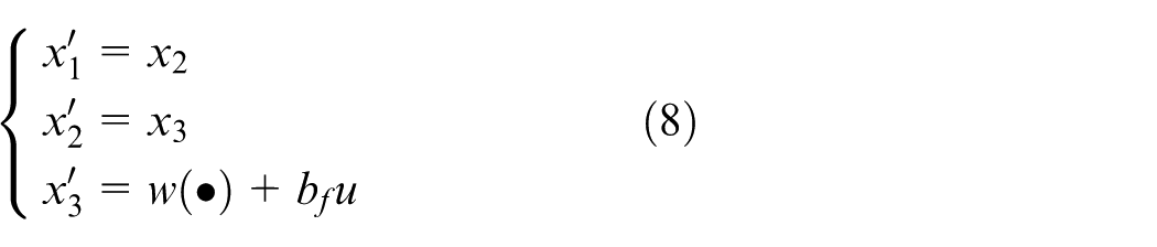
In this paper, by setting a1x1 + a2x2 + a3x3 + a4 = w(
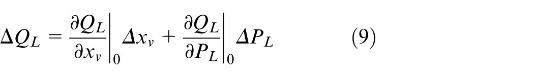
In order to obtain the transfer function, which is convenient for the parameter tuning of the controller. The nonlinear flow equation can be simplified to a linear model, when the servo valve operates near the null position. The linear model of equation (1) is shown in equation (9) 24 :
Let k q represent the flow gain of the servo valve, and k c be the pressure amplification factor, then:
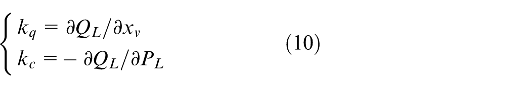
The linear flow equation for the servo valve is expressed as:

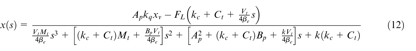
By applying the Laplace transformation to equations (1)–(3) and (9)–(11), we obtain:
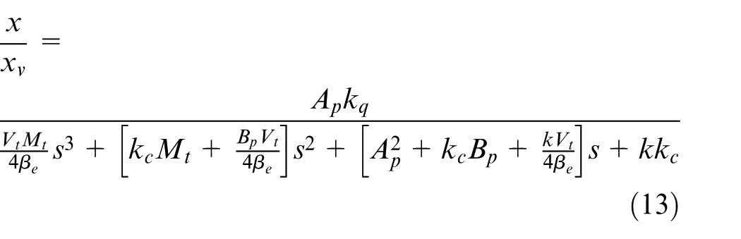
In an unloaded state, the transfer function from spool displacement to hydraulic cylinder displacement is:
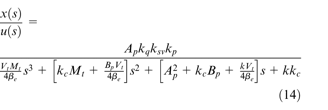
From equations (10)–(13), we derive the transfer function of the system under unload conditions:
Active disturbance rejection controller
ADRC, proposed by Professor Jingqing Han, a Chinese scholar, in 1998, is notable for its integration of all unknown factors in the system model into a single total disturbance. This disturbance is estimated through an observer, and the estimated value is fed back to the controller to form an integrated series system. By employing a tracking differentiator and re-planning the target trajectory, it effectively suppresses overshoot and mitigates the contradiction between rapid response and overshoot.
Tracking differentiator
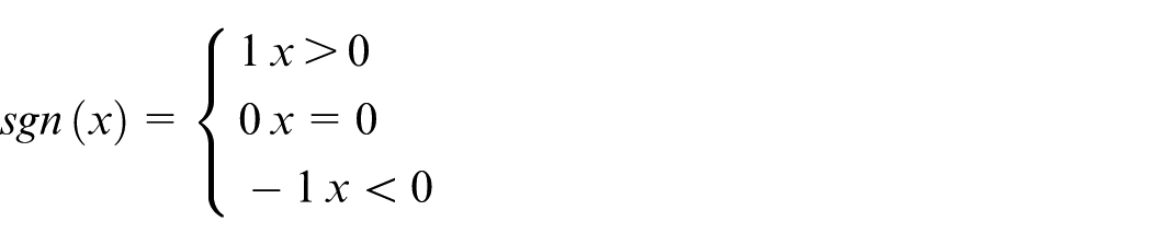
The tracking differentiator (TD) can track the input signal and calculate the input’s differentiation simultaneously. The process eliminates the issue of infinite differentiation that can occur with sudden changes in the signal. The most rapid synthesis function (MRSF) is central to the TD algorithm, and Jingqing Han formulated a specific expression for MRSF,
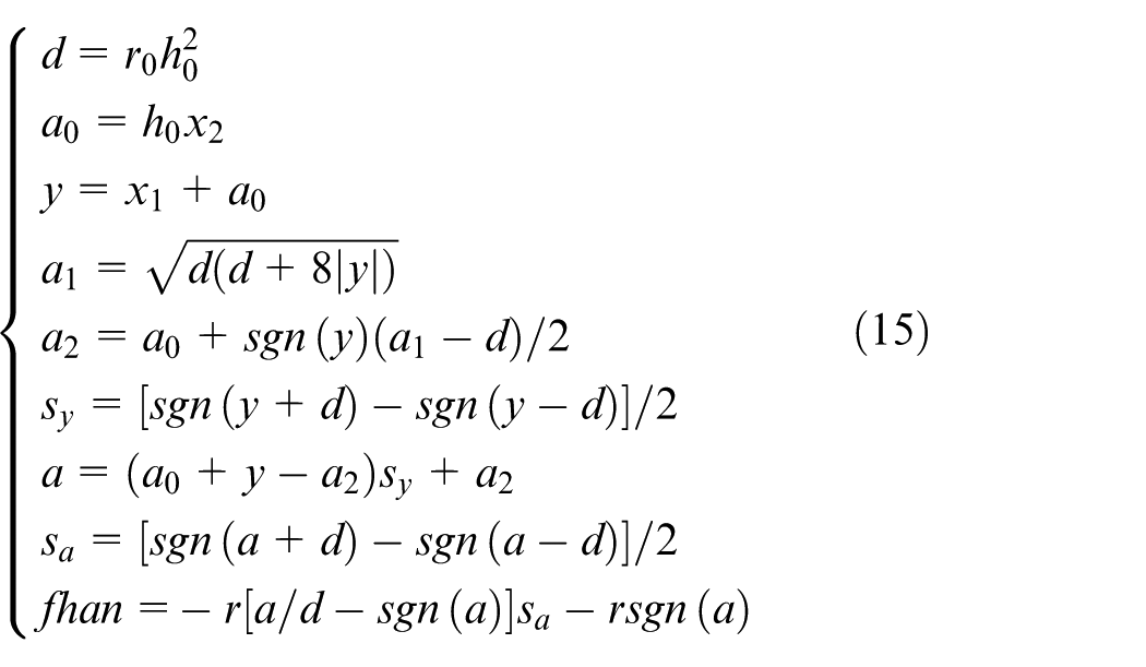
where sgn() is a sign function, defined as:
The parameter r0 and h0 are the control parameters of the fhan() function. The value of r0 influences the tracking speed during the transition process. A larger r0 results in a faster transition but may also cause control signal saturation. Thus, the selection of r0 should be carefully considered based on specific practical conditions. On the other hand, h0 represents the sampling step size of the fhan() function. Adjusting h0 allows for effective filtration of interference in input signals.
The construction of a second-order tracking differentiator is outlined as follows:
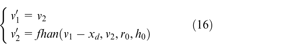
where v1 is the tracked value of the input target displacement computed by TD; v2 is the first-order derivative of the input target displacement.
Non-linear expanded state observer
Assuming that the external disturbance is bounded and its variation frequency is much lower than the bandwidth of the observer. Valve-controlled cylinder system is a state observable system. The total disturbance is either continuous or sectionally continuous. When the above assumptions are met, the non-linear expanded state observer offers superior tracking accuracy compared to the linear observer. For the third-order valve-controlled cylinder system, the nonlinear expanded observer is constructed as follows:
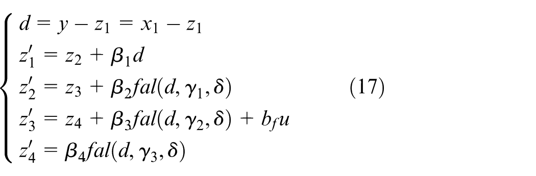
where z1, z2, z3, and z4 are the state variables of the observer. Specifically, z1, z2, and z3 estimate x1, x2, and x3 in the estimation equation, respectively. Concurrently, z4 estimates the total disturbance for the system (14), denoted as z4 ≈ w(•). The coefficients β1, β2, β3, and β4 are the feedback coefficients of the observer. Additionally, γ1, γ2, γ3, and δ are parameters of the nonlinear feedback function fal( ), with the calculation formula:
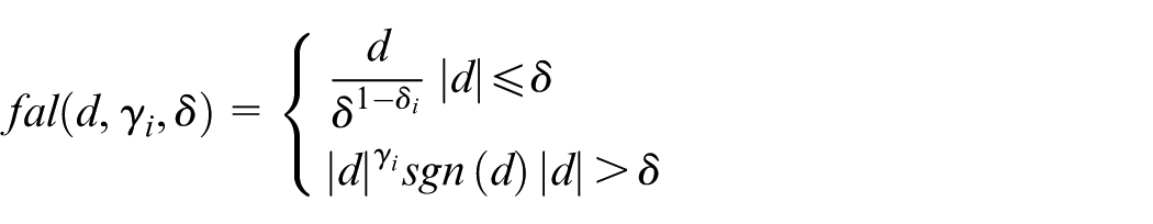
where sgn() denotes the sign function, and δ is a parameter with a relatively small absolute value.
Design of feedback control laws
The original system is transformed into an integrated series system through the feedback control law. Han proposed a nonlinear feedback control method that incorporate the fal( ) function to enhance control accuracy. Simultaneously, the total disturbance estimated by the observer is fed back to the controller to neutralize the impact of unknown factors on control performance. For the third-order valve-controlled cylinder system, the design of the nonlinear feedback control law is as follows:
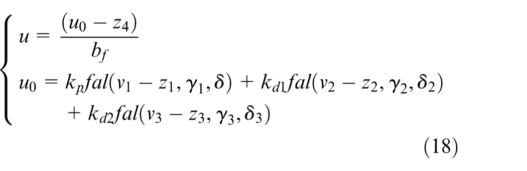
where b f represents the input coefficient obtained through system identification. The parameters k p , kd1, and kd2 are the proportional and differential parameters of the controller, respectively. Substituting u into the state equation (14) yields:
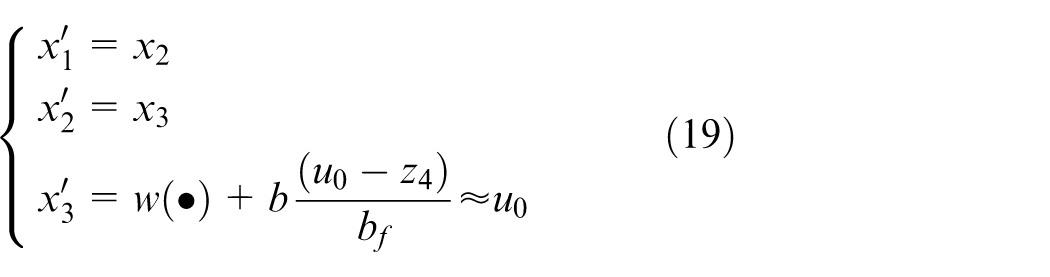
It is evident that the estimation of w(·) by the expanded observer compensates for the unknown disturbances in the system. The original system is effectively simplified to an integrated series system.
Composite control strategy with ADRC and integral feedback
The ADRC block diagram is illustrated in Figure 2. In the diagram, v1–v3 represent the desired displacement and its first and second-order derivatives, respectively. The discrepancies between the TD calculation result and the estimated values from the extended observer serve as inputs for the feedback control law. In the conventional ADRC algorithm, the feedback control law comprises only proportional and derivative feedback. To further enhance system response speed and reduce displacement jitter, it is proposed to incorporate integral feedback of displacement into the control algorithm, represented by e4 in Figure 2. The controller’s calculation formula is provided in equation (20). This study refers to the composite control strategy of integral feedback and ADRC as ADRC + I. The implementation of integral error feedback rapidly eliminates steady-state errors while lowering displacement jitter amplitude, resulting in a more stable output.
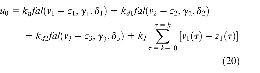
where k I is the coefficient of the integral term. The valve of k I is setted based on the parameter tuning section of next section. τ is the sampling time. By using the discrete integration method of summing up the errors of the last 10 sampling periods. After substituting formula (20) into formula (14), the system is simplified to an integral series type system. By appropriately setting k p , kd1, kd2, and k I , the poles of the system are placed on the left side of the imaginary axis, ensuring the stability of the system.
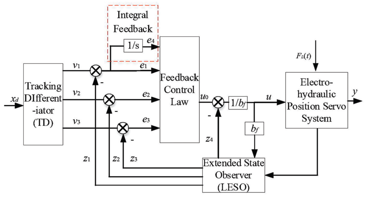
ADRC + I controller structure.
Controller parameters tuning
The numerous ADRC control parameters present challenges in engineering applications of this control strategy. Summarizing practical experience, this paper introduces universal rules for parameter tuning, offering guidance for on-site debugging. The method’s flow chart is depicted in Figure 3. The tuned parameters include the feedback controller’s coefficients (k p , kd1, kd2, k I ), the extended observer’s coefficients (β1–β4), and the control gain b f . The configuration of these parameters critically influences the controller’s effectiveness.
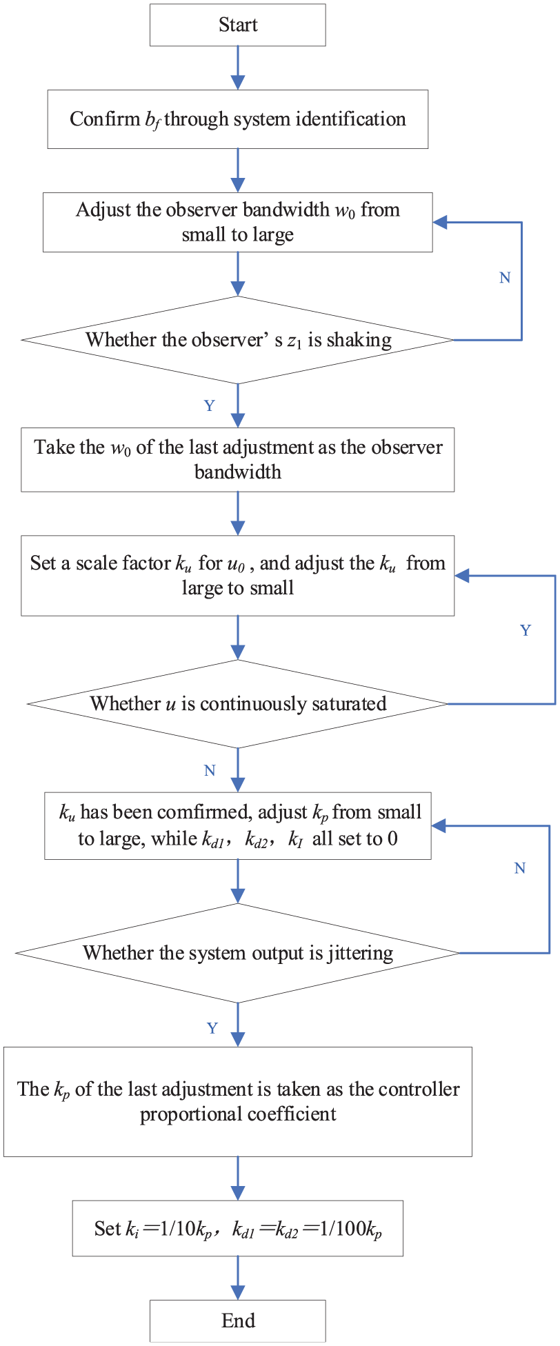
ADRC + I parameters tuning flow chart.
In the flow chart, multiplying u0 by a proportional coefficient k u serves to uniformly adjust the feedback controller’s coefficients, enhancing the efficiency of parameter tuning. This method establishes a relationship between each of the four feedback controller parameters and k p . Once the value of k p is determined, the other parameters (kd1, kd2, k I ) will be automatically determined. The number of tuning parameters is reduced.
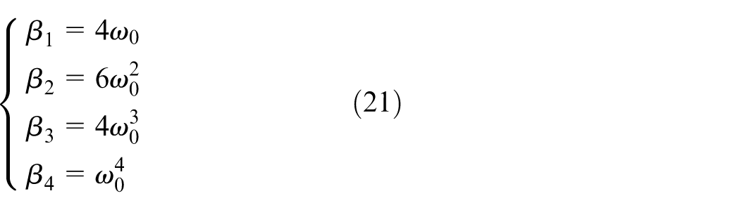
The settings of the parameters in the extended observer, inspired by Zhiqiang Gao’s bandwidth tuning method, the observer’s coefficients are uniformly adjusted by the observer bandwidth ω0. Since a larger bandwidth of the observer is more conducive to improving the response speed of the valve-controlled cylinder system, therefore, ω0 is taken as the maximum value under the condition where z1 does not vibrate. When z1 vibrates, it will cause the control signal to vibrate as well, resulting in vibration of the displacement of hydraulic cylinder. The calculation formula for the observer parameters is:
The improved ADRC parameter tuning method proposed in this paper can set all the parameters of the control strategy by the only three parameters, ω0, k u , and k p . This method will significantly improve the efficiency of parameter tuning. This method is an experimental-based approach and has good applicability for different objects.
Experiment for electro-hydraulic position servo system
The test platform for the electro-hydraulic position servo system comprises three main components: the hydraulic actuator, hydraulic pump station, and control section. As depicted in Figure 4, the hydraulic actuator includes a controlled hydraulic cylinder on the left and a load hydraulic cylinder on the right. The load cylinder applies force to the controlled cylinder via a spring, simulating different loading conditions through displacement changes of the load cylinder. Each cylinder is powered by a dedicated pump sources.
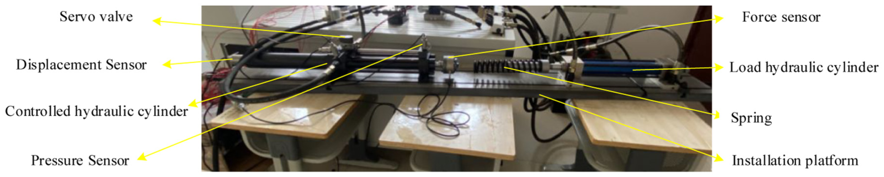
Hydraulic actuator part.
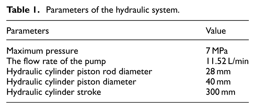
The hydraulic pump station is equipped with an oil tank, motor, hydraulic pump, filter, and pressure gage. The control section is divided into hardware and software components. The hardware setup, shown in Figure 5, consists of a servo valve, host machine, target machine, and NI data acquisition card. The host machine manages the editing of control programs and storage of experimental data, while the target machine computes the control signals in real-time and transmits them to the servo valve via the data acquisition card. The servo valve utilized is the FF102 series nozzle flapper servo valve from China Aviation Industry Group, featuring a rated pressure of 21 MPa, rated current of 40 mA, and a flow rate of 20 L/min. The hydraulic cylinder is equipped with a built-in displacement sensor to monitor the real-time displacement of the piston rod. The software system operates on a Matlab/Simulink Real-Time semi-physical simulation platform, facilitating the easy upload of control programs to the target machine. The parameters of the hydraulic system are detailed in Table 1.
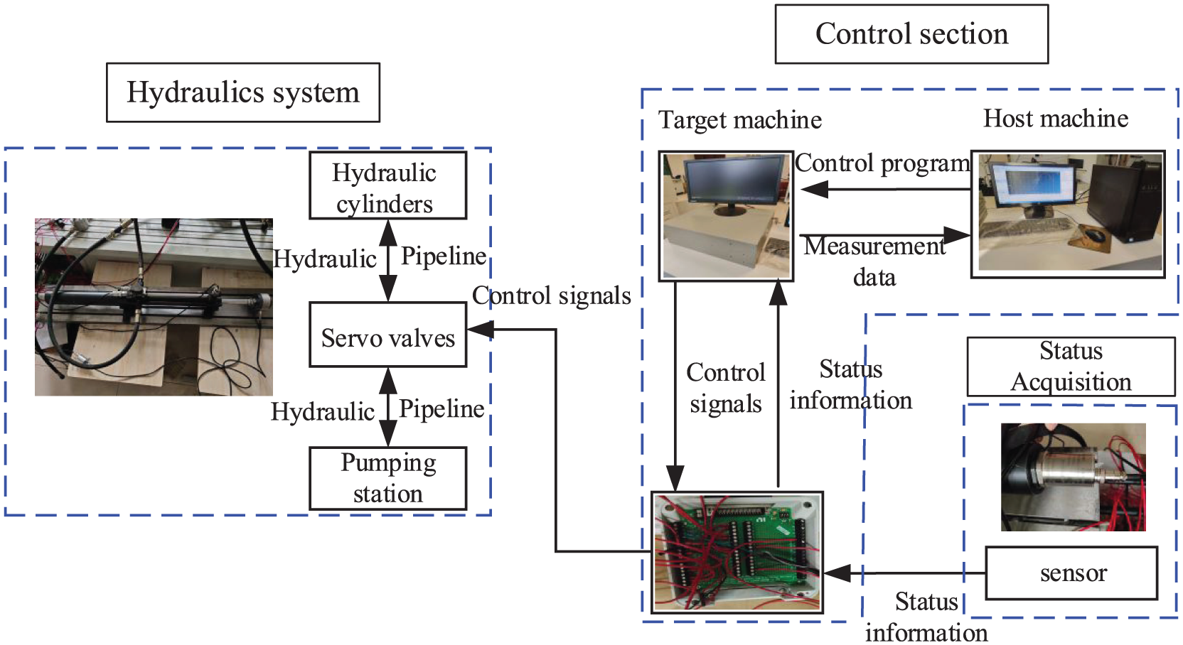
Hardware structure of control section.
Parameters of the hydraulic system.
System parameter identification
The control parameter b f is approximately estimated by identifying the input coefficient b in the state equation (14). A sine voltage signal (22) is applied to the servo valve as outlined in equation (22):

In the unload state, the displacement of the hydraulic cylinder is displayed by the solid line in Figure 6, with a sampling time of 0.0005 s and a total duration of 5 s.
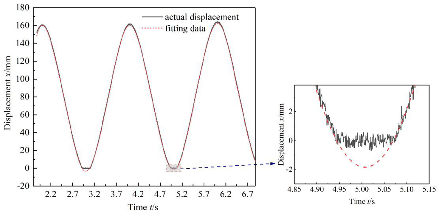
Hydraulic cylinder displacement for system identification.
From Figure 6, it is apparent that the data during the piston’s retraction and when it reaches the endpoint of its stroke, showing a displacement of 0, is distorted. In this study, a data fitting method is employed to calculate and replace the distorted data with fitted data, thereby aligning the displacement trajectory closer to the ideal output. The equation for fitting the displacement data, developed using MATLAB, is:
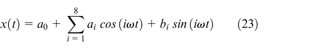
The values of the parameters in the fitting equation are listed in Table 2.
Parameters of the fitting equation.
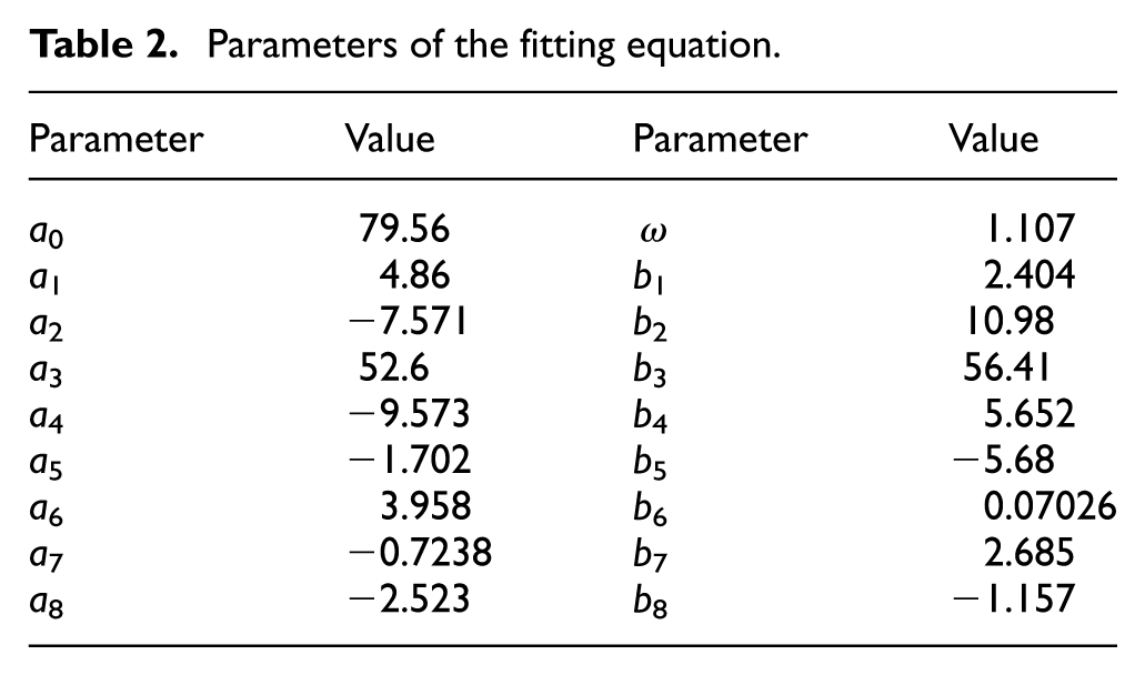
The fitted data is depicted by the dashed line in Figure 6. The fit quality of the equation, with a fitting degree of 0.999, demonstrates exceptional accuracy. Using the fitted data and the system input data, the transfer function of the valve-controlled cylinder system is identified using the MATLAB System Identification Toolbox, as follows:
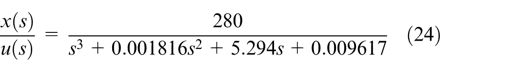
The output of the transfer function, with the corresponding input, is illustrated as the solid line in Figure 7. The accuracy of the system identification is 92.76%, fulfilling the design requirements.
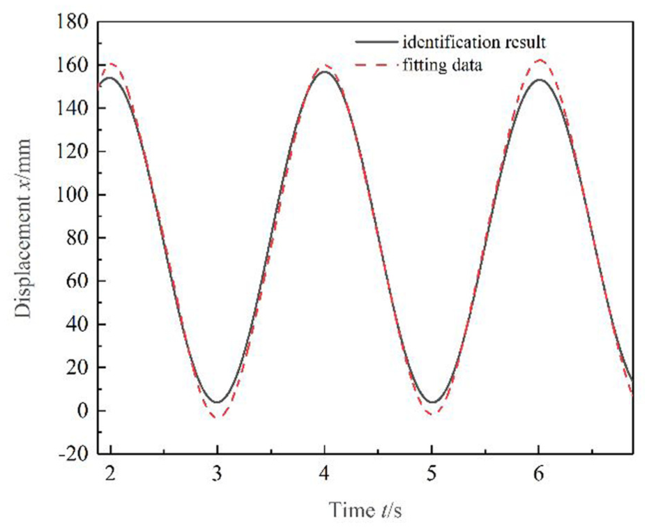
Result of system identification.
According to equation (24), equation (25) is derived.

Comparing equations (12) and (25), we can obtain that bf = 280.
Experimental analysis
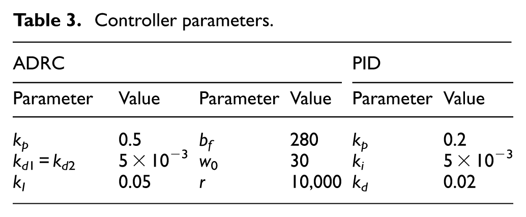
To simulate varying load conditions for the controlled hydraulic cylinder, a sine signal with an amplitude of 4 and a frequency of 0.5 is applied to the load cylinder. Three control algorithms, PID, ADRC, and ADRC + I, were compared. The controller parameters are detailed in Table 3. The reference inputs for this study are step, sine, and square wave tracking signals. For the step tracking signal, at t = 1 s, the target step trajectory reaches an amplitude of 150 mm. The displacement tracking for PID and ADRC is depicted in Figure 8.
Controller parameters.
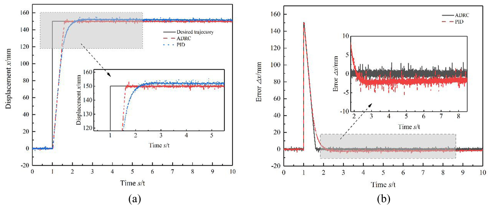
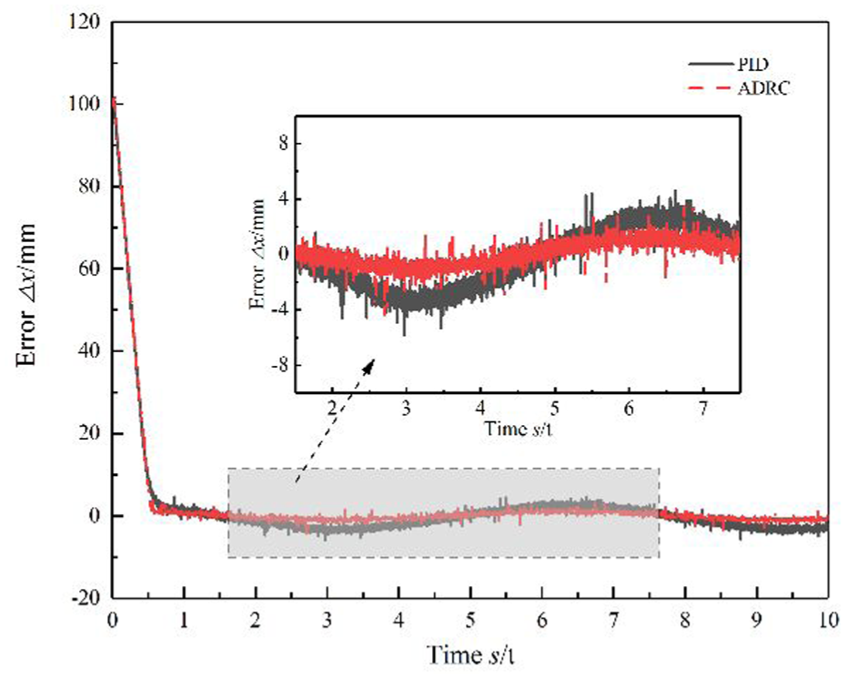
Tracking for step target displacement: (a) displacement curve and (b) error.
The error curves indicate that ADRC achieves a faster response speed and smaller steady-state error compared to PID. The mean steady-state error for ADRC is 0.078 mm, while for PID it is −1.86 mm. The load curve for the controlled cylinder under step tracking conditions is shown in Figure 9.
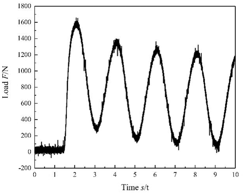
Load of the controlled cylinder for step tracking target.
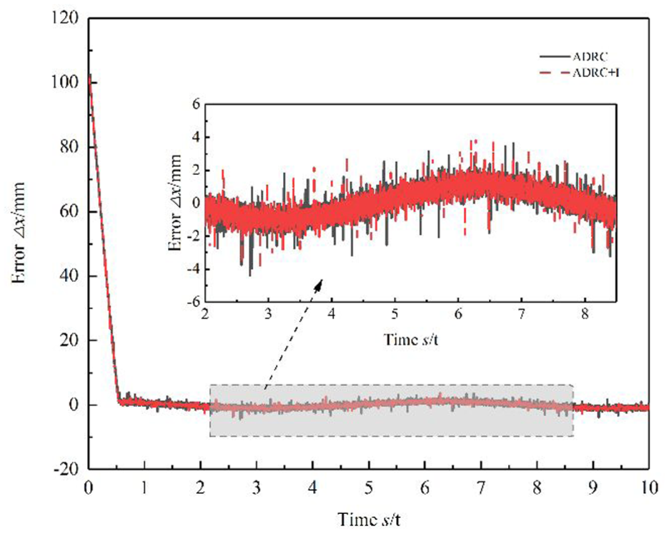
Under unloaded conditions, the displacement tracking errors for ADRC and ADRC + I are illustrated in Figure 10. Since the integral feedback accumulates the tracking displacement error of the latest sampling moment, it leads to a more significant improvement in tracking accuracy under steady-state conditions. The experimental results show that the root mean square (RMS) of tracking error for ADRC is 0.124 mm compared to 0.121 mm for ADRC + I. The degree of displacement jitter has been reduced. The improvement effect is not significant in the transient state. Under the ADRC + I control, the response time and the overshoot are basically the same under ADRC control.
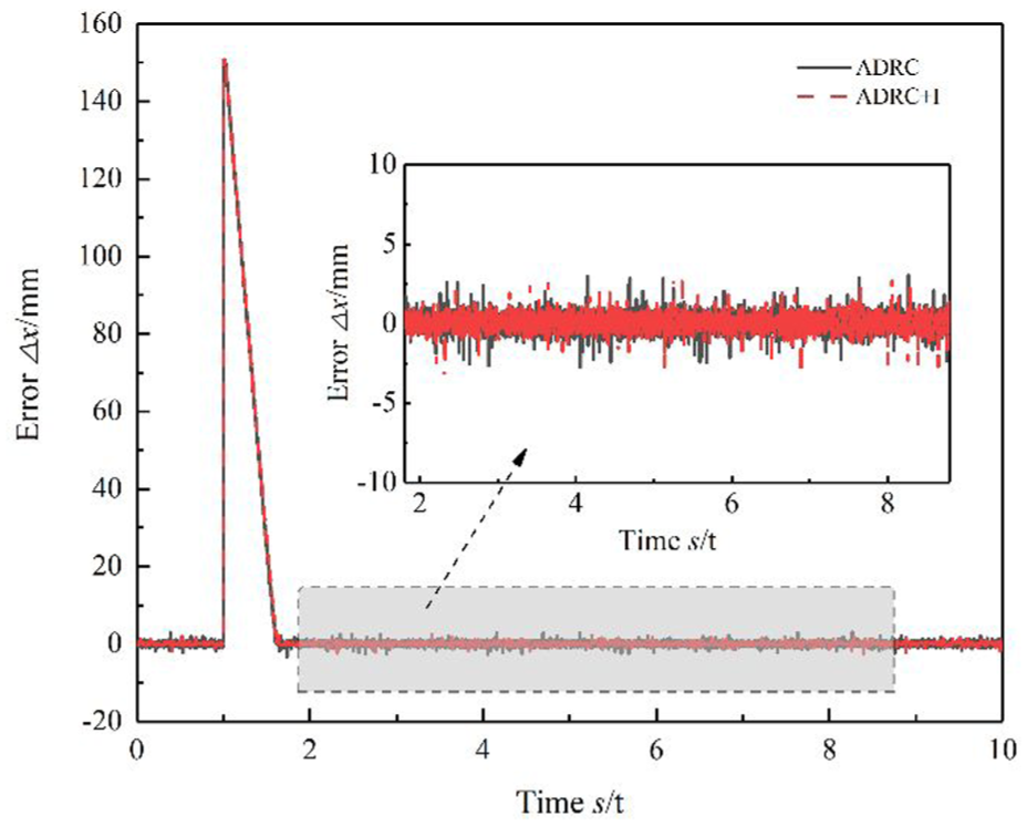
Step tracking error of ADRC and ADRC + I.
For the sine wave target trajectory, the displacement trajectories of ADRC and PID are presented in Figure 11. ADRC demonstrates a faster system response and less fluctuation in steady-state error compared to PID. The RMS of steady-state error for ADRC is 0.734, while for PID it is 4.056 (Figure 12).
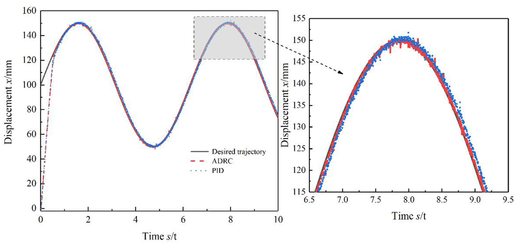
Tracking of sine target trajectory.
Tracking error for sine target trajectory.
When unloaded, the tracking error of ADRC and ADRC + I for the sine target trajectory are shown in Figure 13. The RMS of tracking error for ADRC is 0.595 mm, whereas for ADRC + I, it is 0.593 mm. This reduction indicates decreased amplitude of error jitter under steady-state conditions.
Tracking error of ADRC and ADRC + I for sine target trajectory.
The displacement tracking curve for the square wave tracking signal is displayed in Figure 14. ADRC + I shows a faster response speed and higher steady-state accuracy compared to PID.
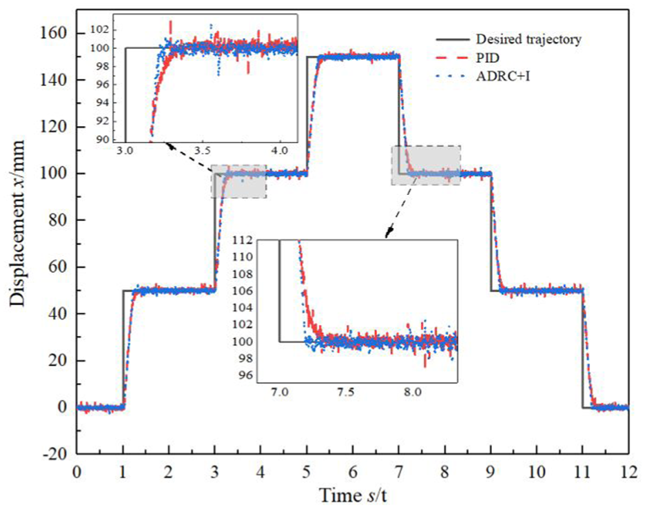
Displacement curve for square wave tracking signal.
Conclusion
(1) For the position control system of the hydraulic cylinder, a new control strategy that combines ADRC with integral feedback is proposed. This strategy enables further reduction of the system’s steady-state error and diminishes output jitter. The experimental results show that, under steady-state conditions, the root mean square of the displacement tracking fluctuation of ADRC + I is reduced by 0.2% compared to ADRC.
(2) Regarding the difficulty in setting control parameters, a parameter tuning method for ADRC based on experimental tests is introduced. The control parameters can be quickly set through the three parameters: ω0, k u , and k p . This method reduces the number of parameters to be set and improves the efficiency of on-site parameter adjustment.
(3) A test platform for the position servo system of the valve-controlled hydraulic cylinder was developed. Under conditions of unknown load, tracking experiments were conducted on three expected trajectories: step, sine, and ramp. The results showed that the steady-state error of the ADRC + I control was reduced by five times compared to the PID control, and the response speed was also significantly improved. This work has provided valuable references for high-precision displacement control of hydraulic cylinders in production practice.
The next step of the work will be to analyze the relationship between the physical parameters of the valve-controlled cylinder system and the ADRC + I control parameters. If the control parameters can be calculated based on the physical parameters, it will avoid the test and measurement process, making the parameter setting of ADRC + I more convenient.
Footnotes
Ethical considerations
This study does not involve any human or animal subjects, nor does it collect any personal or sensitive data.
Author contributions
The authors confirm contribution to the paper as follows: Dongchen E: Conceptualization, Methodology, Supervision, Writing – Review & Editing; Shaoxuan Ning: Software, Validation, Formal Analysis, Investigation; Yihang Li: Resources, Data Curation, Visualization; Jiangtao Yu: Project Administration.
Consent to participate
All authors consent to participate.
Consent for publication
All authors consent for publication.
Funding
The authors received no financial support for the research, authorship, and/or publication of this article.
Declaration of conflicting interests
The authors declared no potential conflicts of interest with respect to the research, authorship, and/or publication of this article.
Data availability statement
All data generated or analyzed during this study are included in this published article.