
Abstract
Optimization of wind turbine aerodynamic performances implies solving the problem in the domains such as airfoil selection, blade rotation angle, chord optimization, number of blades, appropriate tip speed ratio, etc. The current paper studies the effect of blade rotation angle
Keywords
Literature review
Installing large-scale wind turbines is, among other things, associated with investments related to large capital costs as well as the possibility of connecting to the electricity grid. Recently, small wind turbines have appeared as an alternative, especially considering rural areas off the grid and that the average wind speed at heights of about
One possible solution trend for lower-cost renewable energy production is the development and implementation of compact, small-scale wind turbines. But because of factors—high-intensity turbulence, low wind speed and decreased flexibility to changes in wind direction, and perception of possibly high aerodynamic noise levels from the turbines—the usage of small wind turbines in densely populated suburban areas is still relatively limited. Today, there are several research orientations in the field of small wind turbines (SWTs), from the use of contemporary software packages, model wind tunnel testing and laboratory testing, and all this to find the best solution for optimization and performance improvement for small wind turbines. A lot of investigative work has been performed on SWTs, and some of the most representative studies are listed below.
Schmitz theory is used by Al-Abadi et al.
1
in their work to produce a preliminary blade design. The forces, torque, and power extracted by the turbine are computed using the Blade Element - Momentum (BEM) theory. Only the chord and pitch angle distribution are included in the shape optimization because the airfoil form (NREL S809) stays the same. Wind speeds and rotational speeds are limited to those that can be achieved in the wind tunnel and by the generator. Following the identification of the ideal blade shape with the highest
Akbari et al. 2 conducted a multi-objective optimization study to analyze the performance of 10 low Reynolds number airfoils, BW-3, E387, FX 63-137, S822, S834, SD7062, SG6040, SG6043, SG6051, and USNPS4, in a 1 kW wind turbine with regard to the power coefficient and the startup time. The power coefficient and startup time were calculated using the blade element momentum technique, and the optimization was completed using the differential evolution algorithm. The BEM model and computational fluid dynamics (CFD) are the most often used models for forecasting HAWT and VAWT performances. While the lift-to-drag force operating on the turbine blade can be directly calculated with CFD, the BEM model is the outcome of an integral analysis of the wind turbine.
In order to examine its impact on the power coefficient
Khan et al. 5 describes the initial behavior of small horizontal axis wind turbines with low Reynolds numbers and high angles of attack.
The effects of having three or five blades on the dynamic torque, acceleration, and power output of a small horizontal-axis wind turbine are experimentally investigated by Porto et al. 6 The technique utilized to compute the aerodynamic torque produced by the blades during their acceleration stage is presented by the authors.
Sahu and Rathore 7 investigated how low wind conditions affected the torque calculations on 1.5 MW horizontal axes. ANSYS 15.0 was used to apply the interaction analysis method for this fluid structure investigation. The wind’s effect on loading is computed throughout the blade using the Fluent module.
With a fixed pitch blade Darrieus type VAWT, Loya et al. 8 used numerical simulation to study the torque dependency on airfoil geometry.
The impact of offsetting pitching angles and blade counts on the effectiveness of wind-induced rotations VAWT was investigated by Sun et al. 9
The suitability of the CFD model for exploratory analysis was demonstrated by Nguyen et al., 10 who also discovered an optimized design that adopted a pitch angle of +20 instead of the zero-referenced pitch angle and provided a 2.3% higher power coefficient.
Wang et al. 11 analyze SWTs for the Internet of Things (IoT) applications providing an extensive overview of their development, including wind energy rectifiers, power generation mechanisms and IoT applications.
An overview of current developments in modeling and regulating wind power producing systems was given by Young-duan Song et al. 12 Their main goals were to maximize power capture, protect the system with safety systems, and minimize load impacts in order to optimize wind turbine operating throughout three essential modes. The success of this strategy, however, was largely dependent on precise understanding of machine parameters, such as rotor and stator resistances and inductances. Direct torque control (DTC) is an alternative technique for managing machine torque and flux. The authors’ goals were to provide an update on the most recent advancements in sophisticated wind turbine control and to stimulate additional study in the area.
Pitch angle control is a method suggested by Sreenivas et al. 13 and Antonysamy and Joo 14 for regulating wind turbine torque in response to varying wind conditions.
Yilmaz 15 used a custom blade element momentum method that accounted for the effect of aerodynamic coefficients on Reynolds number and showed good agreement with experimental findings.
VAWT design and optimization process was proposed by Kumar et al., 16 Huang et al., 17 and Farhoody et al., 18 using CFD simulations and BEM calculations. Svorcan et al. 19 achieved optimization by combining the created neural networks with the genetic algorithm.
Pitch angle’s impact on HAWT operating performances was investigated by Sudhamshu et al. 20 using the commercial CFD code Fluent; Roul and Kumar, 21 using the commercial software Ansys 15; and Jeong et al., 22 using BEM in conjunction with the ABAQUS standard program.
Using numerical simulation of HAWT with untwisted blades, Thumthae and Chitsomboon 23 and Wibowo et al. 24 identified the ideal angle of attack that produces the maximum output power.
Cai et al. 25 analize the impact of blade rotation on the aerodynamic force of the tower for a range of wind speeds and yaw angles.
From the listed references, it is also apparent that apart from numerical simulation, optimization of the wind turbine design process requires experimental investigation including the wind tunnel.
This paper investigates the effect of blade rotation angle in a small wind turbine HAWT on the torque and mechanical power. Two models of wind turbine blades are analyzed. The first part of the paper employs numerical analysis, that is, Ansys CFX and Ansys Fluent software packages, in order to determine the wind turbine aerodynamic characteristics. In the second part, experimental measurements of the torque are performed at appropriate number of generator revolutions with and without loading, and comparison is done with the results obtained from numerical analysis. Box Wilson’s plan of experiments is used for the experimental part. 26
Even in situations when these parameters are entirely unknown, Movahhed Neya et al. 27 suggest a disturbance observer-based controller designed to maximize power extraction from a wind turbine system. In order to estimate nonlinear terms resulting from unknown model parameters and an unknown control coefficient, the controller integrates a disturbance observer. It accomplishes this by estimating the nonlinear disturbances only from tracking error feedback. Unlike other research, the authors of this work make the assumption that the parameters of the drive-train model and the aerodynamic model are both completely unknown.
Numerical analysis
Evaluation of aerodynamic performances was carried out using software packages Ansys CFX and Ansys Fluent. Both CFX and Fluent employ the finite volume method to solve the equations that describe fluid flow. Variable values such as mass, energy or moment are calculated in control volumes that make up the computational grid.
In the case of the finite volume method for discretization, CFX uses the vertex-centered method, 28 whereas CFD uses the cell-centered method. 29 Outputs from the computations may include generated aerodynamic forces, torque, power, pressure distributions along the blades, wakes detaching from blade tips, etc.
The analysis included two blade models of the manufacturer ‘Marsrock’: V-Blades length 65 cm and M-Blades length 58 cm, airfoil class SD 7003, Figure 1. These blades were taken for testing, because they are made exclusively for wind turbines of small dimensions, and as such they have a special airfoil (SD 7003) and twist angle.
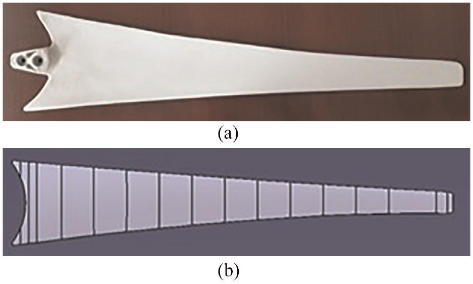
Physical (a) and CAD model (b) of a blade.
The two blades are additionally compared by contrasting their basic geometric features (relative chord and twist angle) at three characteristic cross-sections (corresponding to 25%, 50%, and 75% blade span/length), and these values are listed in Table 1.
Values of chord and twist angles along the blades.
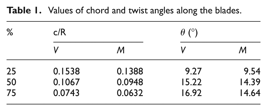
It can be observed that apart from having higher solidity, blade V is also slightly more curved, and their effect on wind turbine output characteristics will be shown by numerical analysis and experimental investigations.
Numerical analysis employed CFX and Fluent, transport equations, that is, the system of equations with the
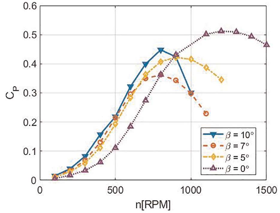
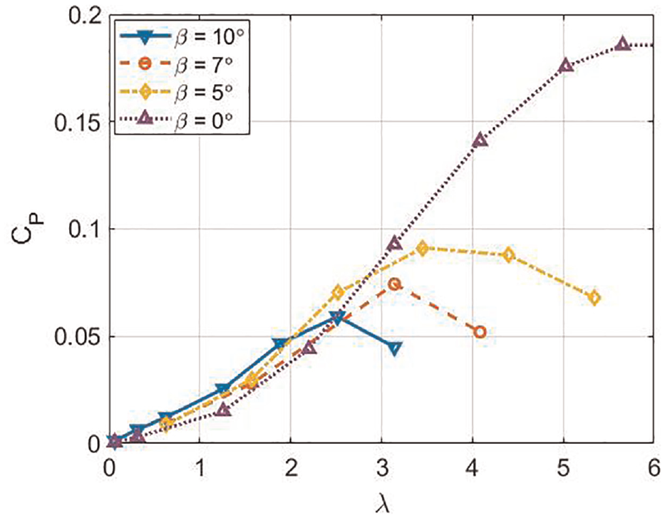
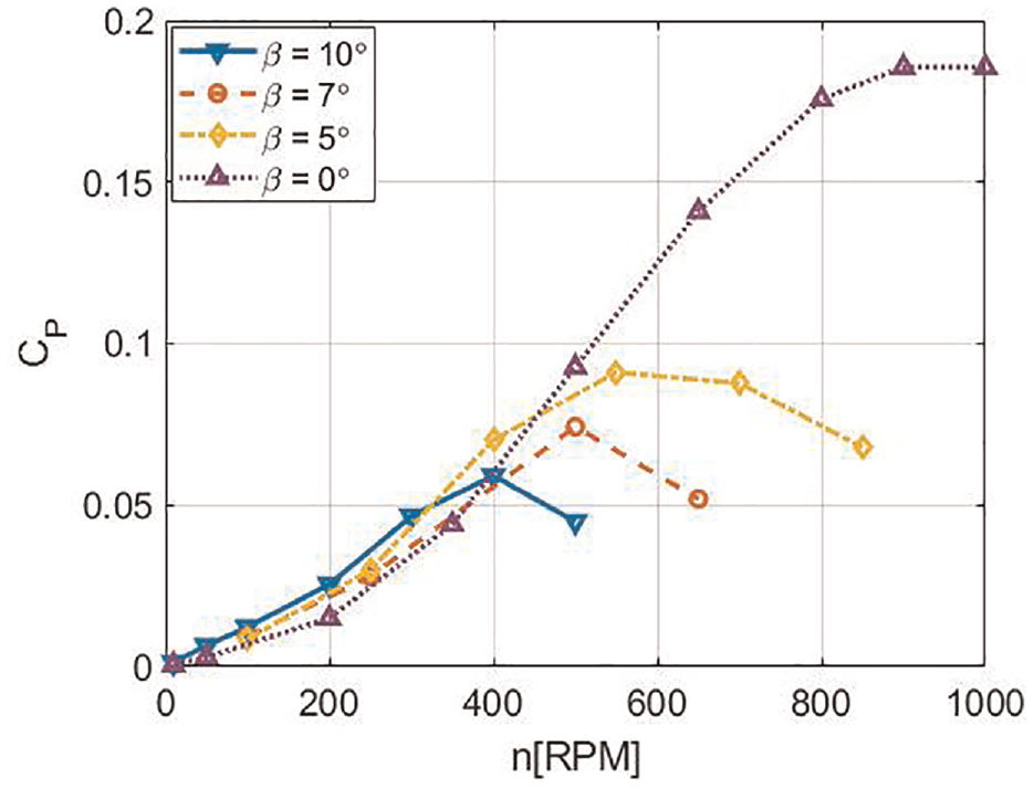
Figures 2 to 5 show change of the power coefficient
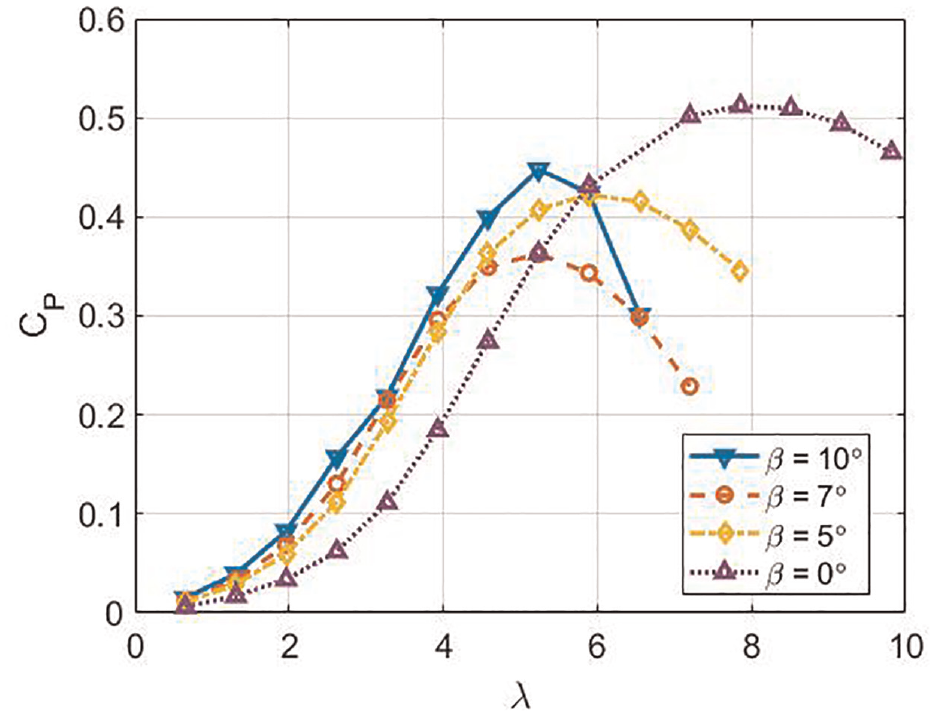
Change of power coefficient (
Change of power coefficient (
Change of power coefficient (
Change of power coefficient (
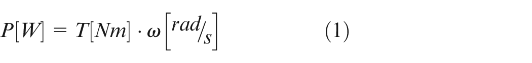
Wind turbine mechanical power can be determined via the momentum that causes rotary motion and angular velocities:
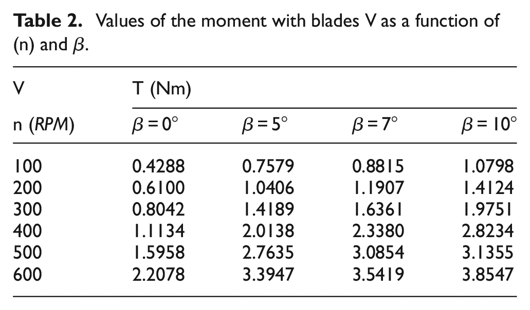
For a specified wind speed of
Values of the moment with blades V as a function of (n) and β.
Values of the moment with blades M as a function of (n) and (β).
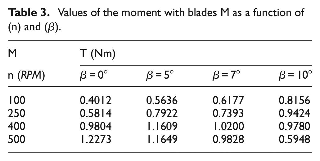
Using equation (1) the wind turbine mechanical power was determined and diagrams of change are shown in Figures 6 and 7.
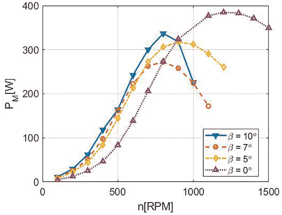
Change of the wind turbine mechanical power (
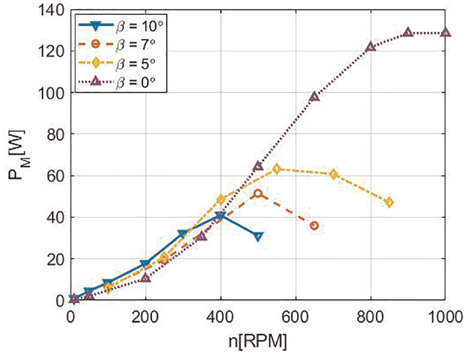
Change of the wind turbine mechanical power (
Experimental setup
Experimental part of the investigation involved torque measurements on a HAWT model with considered blades at appropriate angle
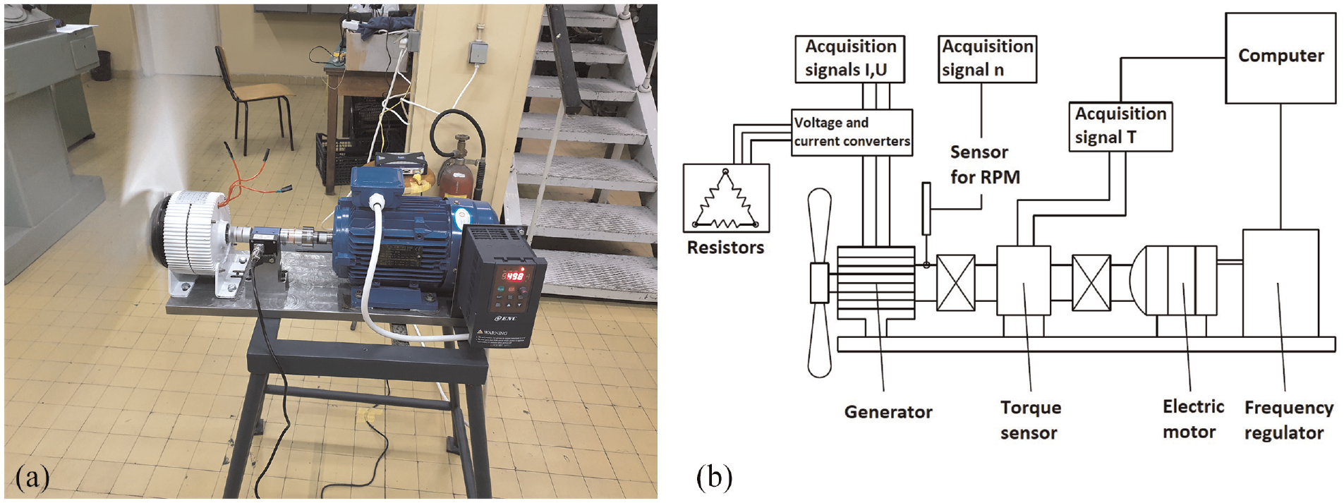
HAWT model (a) and schematic representation of measuring equipment (b).
A wind turbine consists of the electric motor, two couplings, torque sensor, three-phase a synchronous generator, frequency regulator, laser tachometer for RPM, and voltage measuring device. A synchronous generator with permanent magnets (model Logihitech, 48 V) of 300 W nominal power and max operating number of revolutions
Measurement results
In the first part of testing, the generator was not loaded with a resistor, except for the internal resistance of the generator of 3.9 Ω. Figures 9 and 10 show measurement results for the torque on the generator shaft in the function of a specified number of revolutions
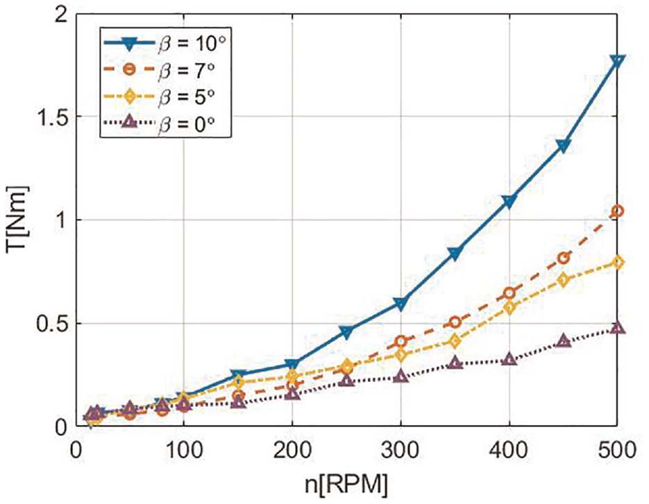
Change of the torque in the function of the number of revolutions for appropriate blade V pitch angles.
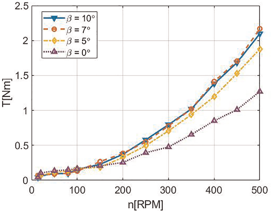
Change of the torque in the function of the number of revolutions for appropriate blade M pitch angles.
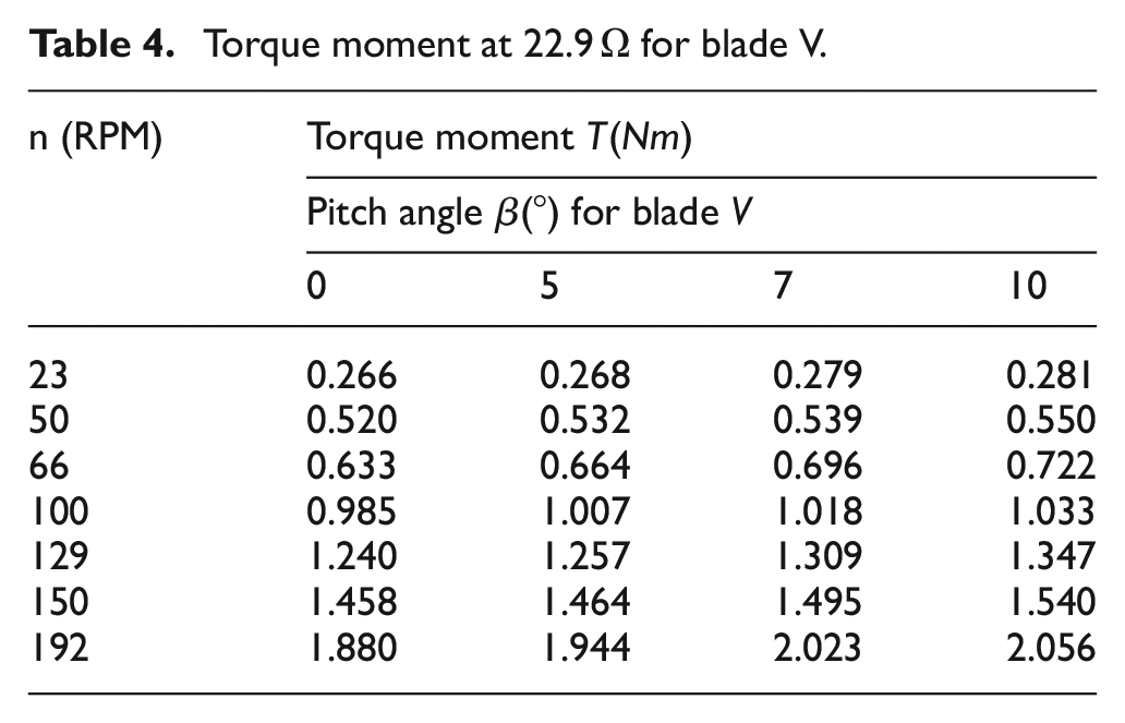
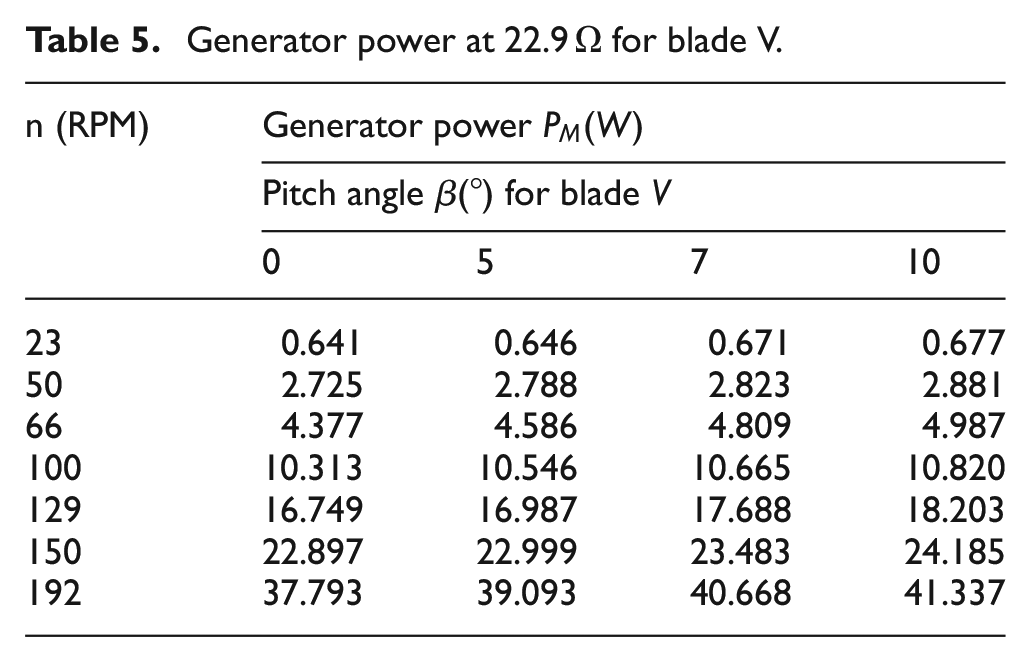
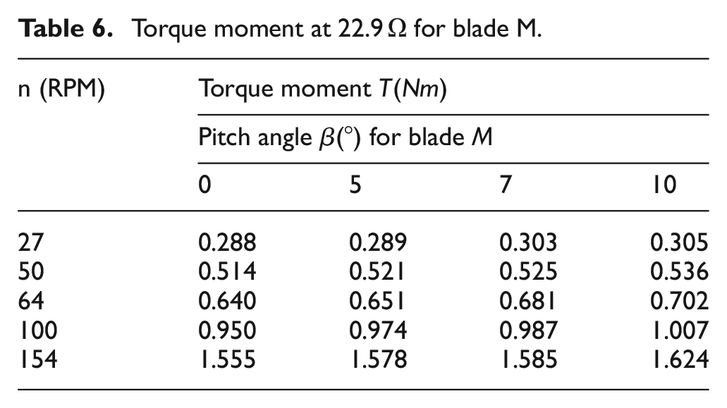
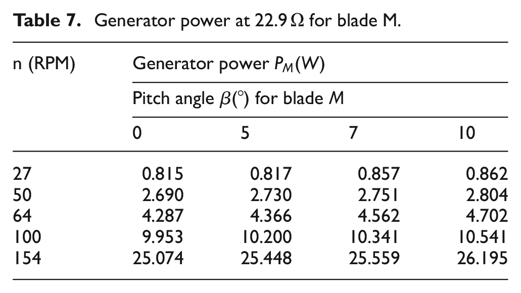
In the second part, the generator was loaded with three resistors connected in a triangle with a 22.9 Ω resistance. The measured resistance of the load resistors in the wind tunnel is 22.7 Ω, while the calculated value is 23.03 Ω. The difference comes from the positive temperature coefficient of the resistors used. The value of 22.9 Ω was adopted for the calculation due to the expected temperature of the resistor during the dissipation of the power obtained from the generator. Tables 4 and 5 present the results of torque measurements, and Tables 6 and 7 appropriate values of the mechanical power.
Torque moment at 22.9 Ω for blade V.
Generator power at 22.9 Ω for blade V.
Torque moment at 22.9 Ω for blade M.
Generator power at 22.9 Ω for blade M.
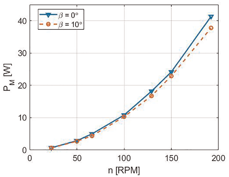
Figures 11 and 12 display diagrams of change in the mechanical power on the generator with blades (V and M) in the function of
Change of mechanical power on the generator with blade (V) in the function of (
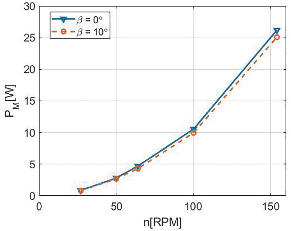
Change of mechanical power on the generator with blade (M) in the function of (
In order to determine the character of change in the torque and mechanical power, regression analysis was performed using DataFit software package and polynomial regression model
The parameters of the polynomial regression model.
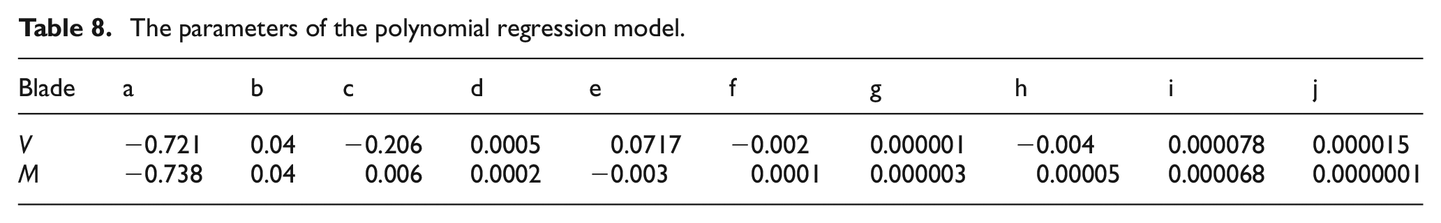
It can be seen from the Table 8 that coefficients
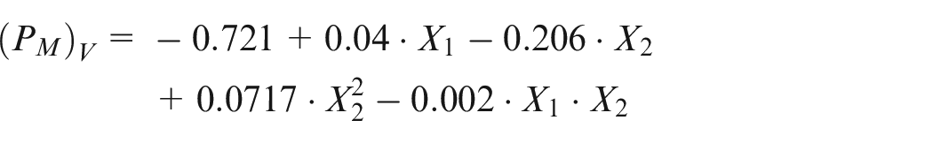
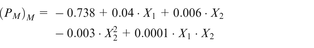
Figures 13 and 14 show the character of change in the mechanical power and it is evident from them that change is not linear.
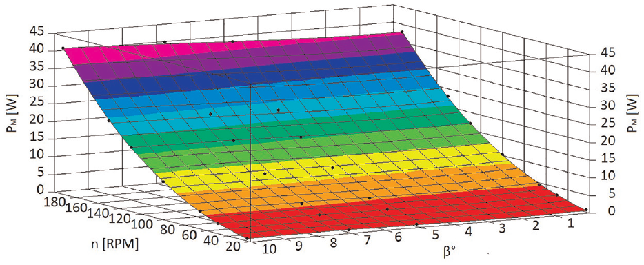
Diagram of change in
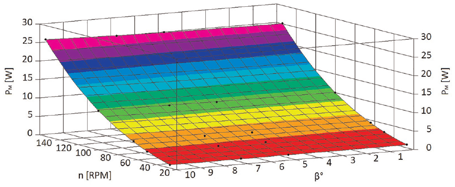
Diagram of change in
Based on the values from the table, it can be concluded that the character of the influence of the pitch angle on the mechanical power is not linear.
Discussion
Based on numerical analysis and diagrams in Figures 2 to 5, it is evident that at blade rotation angle (V) by
Analogously, when observing the number of revolutions on the rotor (generator), the results indicate that at the change of
Turning the blade (M) by
Data shows that blade V geometry is more favorable compared to blade M because higher
At the number of revolutions
Experimental data indicates that the effect of blade rotation angle
Comparing the values obtained for the torque in Ansys (Tables 2 and 3) and experimental investigation on the unloaded generator (Figures 9 and 10) at the same number of revolutions, the difference is observed as a result of the influence of the mentioned mass moment of inertia. Namely, in blade (V) for the considered rotation angles
Considering the generator loading, this implies that it is connected to a consumer that has the appropriate resistance. It is commonly known that the accomplishment of the appropriate number of revolutions on the loaded generator requires a higher torque compared to the case of unloaded generator. Higher blade torque needs greater lift/resistance force, whereby the flow mechanism changes as a result of blades deformation due to increase in mentioned forces.
The impact of blade rotation angle (V) from
Generator loading has impact on the moment, and thereby on the mechanical power, because the accomplishment of the same number of rotations requires higher torque in loaded than in unloaded generator. It is known that the wind turbine power P is directly coupled with the wind available power
Based on diagrams in Figures 9 and 11, it can be concluded that at a given number of generator rotations the torque increases as the resistance increases (the needed mechanical and therefore electrical power). Namely, with resistance decrease from 22.9 Ω–3.9 Ω on a wind turbine with angle
In wind turbine with the blade (Figures 10 and 12) with angle
Conclusion
A blade with its geometry, material and manufacturing technology has a significant effect on the wind turbine work behavior and therefore on its output characteristics. The analysis of used blades and their performances was carried out applying software packages Ansys CFX and Ansys Fluent. Numerical analysis confirmed that as the blade (V) turning angle
Analysis indicates that the blade V geometry is more favorable compared to blade M, because a higher value of the
Experimental setup and methodology enable examining the influence of different blade models on wind turbine output characteristics and comparison with the values obtained from numerical analysis. Comparing the values obtained for torque from Ansys and experimental investigation on the unloaded generator at the same number of revolutions, the difference is observed that developed as a result of the influence of the mass moment of inertia of the rotor, generator and friction present in bearing.
Methodology also allows for measuring the torque and mechanical power at loading (connecting) the generator to a consumer. Thus, at loading of 22.9 Ω, the results show that with increase of rotation angle the moment and mechanical power increase in blades V and M.
Footnotes
Declaration of conflicting interests
The author(s) declared no potential conflicts of interest with respect to the research, authorship, and/or publication of this article.
Funding
The author(s) disclosed receipt of the following financial support for the research, authorship, and/or publication of this article: This research work was supported by the Ministry of Science, Technological Development and Innovation of the Republic of Serbia through contract No. 451-03-65/2024-03/200105 from 5 February 2024.
Ethical approval
Ethical approval is not applicable to this study as it did not involve human or animal subjects.
Data availability statement
Data sharing not applicable to this article as no datasets were generated or analyzed during the current study.