
Abstract
One of the recent methods to improve the performance of horizontal axis wind turbine is to attach a winglet at the tip of the blade of these turbines. Winglets reduce the effect of vortex flow at the blade tip and thus improve the performance of the blade. This article presents a parametric study using the computational fluid dynamics (CFD) modeling to investigate the capability of a winglet to increase the turbine power of swept blades as well as straight blades of a horizontal axis wind turbine. The effects of winglet direction, cant angle, and twist angle are studied for two winglet orientations: upstream and downstream directions. The numerical simulation was performed using ANSYS Fluent computational fluid dynamics code. A three-dimensional computational domain, cylindrical rotationally periodic, was used in the computations. The k-ω shear-stress transport turbulence model was adopted to demonstrate turbulence in the flow. Results show that horizontal axis wind turbine with winglet and sweep could enhance more power compared to their equivalent straight or swept blade. The best improvement in the coefficient of power is 4.39% at design tip speed ratio. This is achieved for downstream swept blades with winglets pointing in the upstream direction and having cant and twist angles of 40° and 10°, respectively.
Introduction
Wind turbine blades like aircraft wings suffer from three-dimensional effects especially at the blade tip. The flow at the blade tip is affected by the pressure difference on both sides of the blade that creates a tip vortex flow. This leads to lift force reduction and an introduction of additional drag, called the induced drag. 1 Most of the efforts to understand the tip losses showed that the change of tip geometry greatly affects the tip vortex effects. The work carried by Whitcomb, 2 introduced the first streamlined vertical winglet that was placed at the wing tip. Airfoil-shaped winglets cause tip vortex diffusion that leads to a sensible reduction of induced drag. 2
Pervious works1,3–10 that used winglets with the traditional straight blades concluded that the power output of the wind turbine increased by adding the winglets. Matheswaran and Miller 3 used lightweight winglets to improve the power coefficient (CP) without increasing the load on the blade. Results show that the power coefficient could be increased by 2.45%. Al-Abadi et al. 4 tested different designs of winglet to compare with the effect of having high turbulent flow. Comparison shows that the chance to capture more energy increases with higher level of turbulence not with using a winglet tip. Farhan et al. 5 tested two different winglet configurations, while two cant angles, three winglet lengths, and two blade profiles were altered. The best achievement was accomplished by a 15-cm rectangular winglet with S809 airfoil and 45° cant angle, where the power increases up to 9.4%. Ostovan et al. 6 performed an experimental examination for the impact of winglet on the wake flow near the tip and on the tip vortex characteristics. Results show that adding winglet increased the diffusivity of the velocity gradient while the vorticity and turbulent kinetic energy are reduced at the wake flow near the tip.
Sessarego et al. 7 applied a vortex code to investigate the performance of three forms of horizontal axis wind turbine (HAWT) blade: straight, downstream winglet, and backward sweep. Where the winglet starts at 97.3% of the blade length. Results show that the blade with backward sweep increased the power around 1.5% and with downstream winglet increased the power by around 1.3% compared to the baseline straight blade. Reddy et al. 8 carried out shape-design optimization for designing the winglet of HAWT. The presence of an optimized winglet increased the power coefficient by 4.5% and increased the axial thrust force coefficient by 4%; however, the blade-twisting moment is still the same. Johansen and Sorensen 9 showed that adding a winglet raised the output power for wind speed higher than 6 m/s is increased maximum by about 1.4%, while the thrust also raised by about 1.6%. The output power was found to be augmented further when the winglet toward downstream direction. Gertz 1 mentioned that adding winglet augmented the power by roughly 5% at wind speeds between 6.5 m/s (tip speed ratio, TSR = 6.3) and 9.5 m/s (TSR = 4.3), while the performance deteriorated above and below this speed range. Saravanan et al. 10 showed that the presence of winglet will increase the power coefficient for low wind speed regions (1.9 ≤ TSR ≤ 3.5). Saravanan recommended that the appropriate winglet height with the minimal curvature radius would catch more power in low wind speed area.
Modern winglets could be defined by the following parameters that are considered when designing: height, cant angle, sweep angle, toe angle, and twist angle as shown in Figure 1.

Geometrical parameters of a winglet. 11
In this work, swept blade with two orientations of the winglet will be considered to study the effect on enhancing wind turbine output. In the first orientation, the winglet is directed toward the blade-pressure side, while in the second orientation, it is directed toward the blade-suction side. Effect of cant and twist angles will also be studied.
Wind turbine blades and CFD methodology
Wind turbine baseline blade
A model experimental HAWT was used to carry out this study. This experimental turbine was selected as its dimensional details and actual measured performances are available. The baseline turbine is three-bladed upwind. The blades were mounted on a 0.09-m hub. The model geometry was laid out using blade element momentum (BEM) method, incorporating corrections for tip losses and the thrust force. Table 1 shows the blade specification of the model wind turbine.
12
The turbine was operated during the experiment at constant wind speed of
Specification of the baseline blade of the model wind turbine. 12

Swept blades under investigation
A previous research using computational fluid dynamics (CFD) simulations was directed by Khalafallah et al. 13 to study the effect of some of the variables, related to blade sweep, on the performance of the aforementioned turbine. The CFD study included the effect of blade curvature of sweep, sweep-starting point, and sweep direction. Four sweeping curvatures, different sweep-starting points, were selected from previous studies related to swept blades.14–17 These sweeping curvatures were tested alternately in four sweep directions: relative to blade rotation; forward (f) and backward (b), and relative to flow; upstream (u) and downstream (d).
Results showed that the sweep in the downstream direction with a curvature taken from a study by Ashwill et al. 14 that starts at 25% of the blade (swept 10d) and the sweep in the direction of the blade rotation that starts at 25% of the blade with a curvature taken from the study by Ashwill et al. 14 (swept 10f) had the best improvement as compared to the baseline 0.9-m straight blade. 13 Therefore, swept blades 10d and 10f will be chosen for further study with winglets. The baseline 0.9-m straight blade will be studied also with winglet tip for a comparison purpose.
A selected set of CFD results
13
are presented in Table 2 for swept 10d and swept 10f blades, in addition to results of the baseline straight blade, where CPD is the power coefficients at design TSR of 6 and
Computed CPD of straight blade and swept blades 10f and 10d. 13

Computational analysis
The same techniques that were used in previous work 13 have been applied in this article. Visual Basic was used to determine the Cartesian coordinates of the blade sections including winglet tip. Then, SolidWorks software was used to build the blade and winglet tip as well. After that, to generate the meshing geometry for CFD work, ANSYS ICEM software was used. The whole domain including the blade surface are unstructured meshes. Figure 2 shows the mesh surface of upstream winglet tip attached to a downstream swept blade 10d. Numerical modeling and simulation of the winglet was carried out using ANSYS Fluent CFD code.

Surface mesh on swept 10d with winglet tip, cant angle = 60°.
Figure 3(a) shows the 120° computational domain with periodic condition at the boundaries to simulate the fully 3D flow. The domain extensions are also explained in Figure 3(a) where R is the rotor radius. The boundary conditions are indicated in Figure 3(a), where a constant wind speed was specified to the inlet and far-field boundaries. In addition, no slip boundary condition was applied to the blade surface.
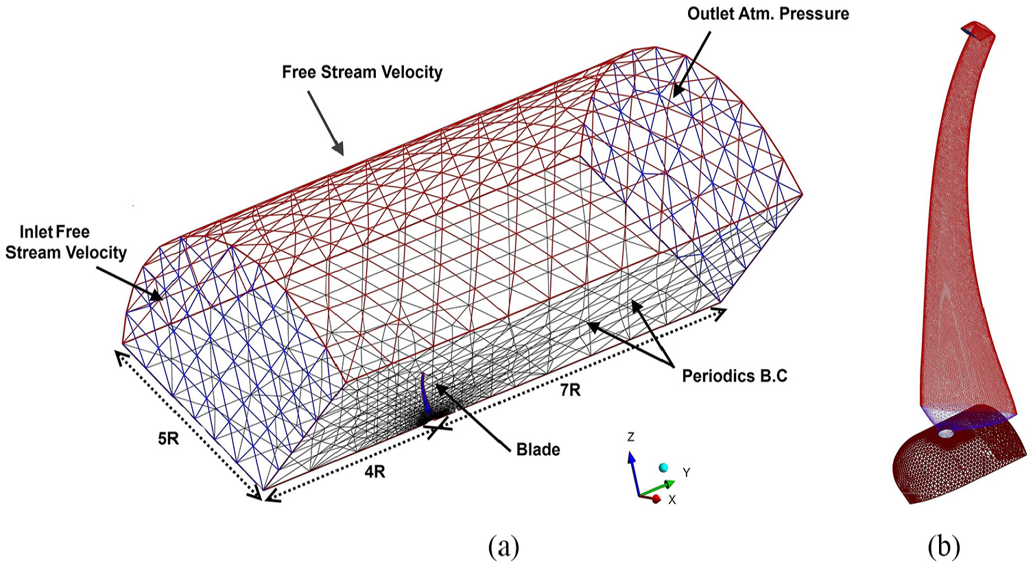
(a) The meshing domain and (b) the blade surface and winglet tip meshing.
All cases under investigation in this study will be built to have around 1.8 million grid elements. This grid size shows good accuracy and economy of solution for the CFD study of baseline blade 13 and swept blades. 18 Therefore, the 120° computational domain dimensions, Figure 3(a), are selected as those in the mentioned studies13,18 and so the grid size can be used with confidence. The same parameters of the previous works13,18 were used in this article for the moving frame, 19 boundary layer settings, turbulence model, 20 solution control arrangement and pressure-velocity coupling. 21 The k-ω shear-stress transport (SST) turbulence model was used to represent turbulence in the simulation process of the wind turbine. The k-ω SST model was chosen, as it has achieved success in the turbulent flow simulation over wind turbine airfoils. 20 Figure 3(b) shows the meshing of blade surface including winglet tip. Simulation and numerical solution of all studied turbines was created using ANSYS Fluent CFD code.
Results and discussion
An initial numerical attempt to search for increasing the turbine power using winglet has been carried out for the baseline 0.9-m straight blade HAWT. Then two superior swept blades have been selected from previous work 13 to be tested with winglet at the tip. These swept blades had been derived from the baseline 0.9-m blade to investigate the change in power coefficient. In order to focus on the effect of winglet parameters on the turbine performance, the computations have been performed, at first, at the design TSR of 6.
Winglet configuration
For the ease of comparison, the length of the blade was considered independent on the value of the cant angle. So, the blade length was kept constant by making winglets travel down/up through the blade according to the value of cant angle, see Figure 4. However, blades were laid out so that all winglets started at r/R = 0.95%, winglets are connected to the blade directly at this radius.

Change of cant angle to maintain the rotor radius constant.
It should be noted that, the winglet height will increase with the increase of the cant angle. This may lead to two opposite effects: enhancing the performance due to the presence of the winglet and some increase of the resisting drag force due to the increase of winglet height for higher cant angles. It is difficult, in this study, to separate the effects of the two variables (cant and height), and for overall comparison, it will be considered as cant angle effect.
Straight blade with winglet
The straight blade with winglet tip of baseline 0.9-m HAWT 12 will be tested numerically. Both pressure side and suction side winglet direction will be investigated. For each winglet direction, the twist angles −2°, 2°, and 10° will be studied at each of cant angles 20°, 40°, and 60°. A total number of 18 winglet of straight blade have been examined, see Table 3.
Change in power coefficient
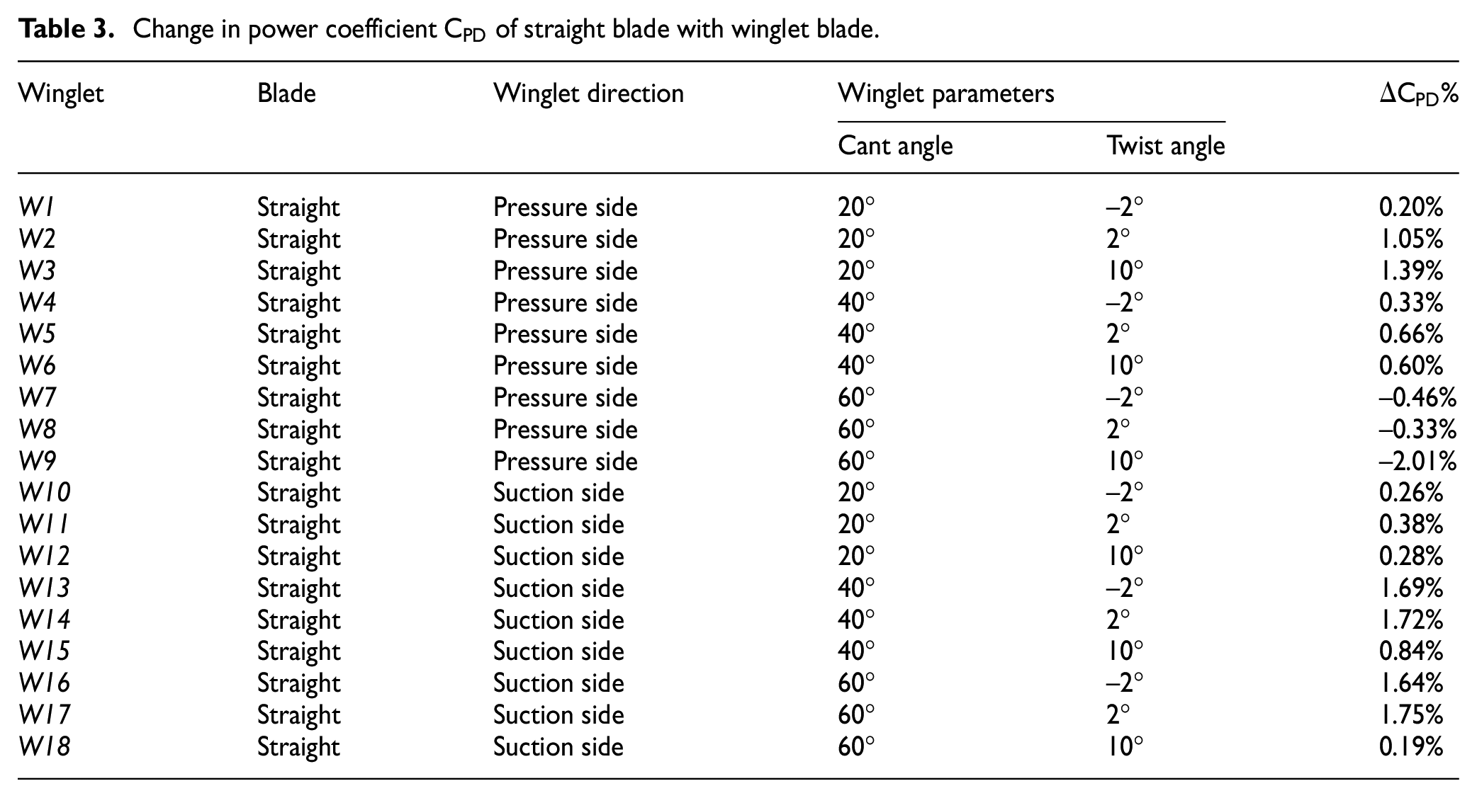
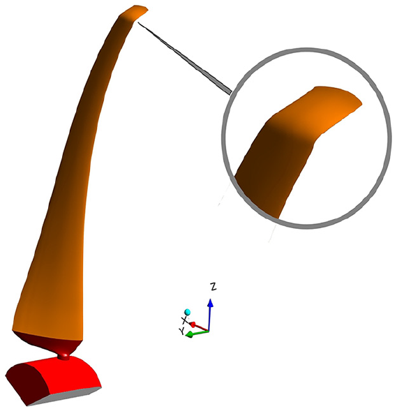
Figure 5 shows the isometric view of a straight blade with pressure side winglet and cant angle of 40° and twist angle of 10° with zoomed view of the winglet. Table 3 shows the simulation results of 18 winglets of straight blades.

Isometric view of a straight blade with pressure side winglet and cant angle of 40° and twist angle of 10°.
Results in Table 3 show that winglet addition, in general, increases power output except for cases W7, W8, and W9, in which the winglet is on the pressure side and cant angle is 60°. The best increase in power coefficient,
Swept blades with Winglet
The effect of using swept blades with winglets will be studied for the two cases (swept 10d and swept 10f), 13 whose properties are shown in Table 2. Winglets pointing to pressure and suction sides will be adopted. For swept blade 10f, and each winglet direction, the twist angles −2°, 2°, and 10° will be studied at each of cant angles 20°, 40°, and 60°. A total of 18 winglets for swept blade 10f and 15 winglets for swept blade 10d have been investigated, see Tables 3 and 4, respectively.
Change in power coefficient

Figure 6 presents the isometric view of swept case 10f with pressure side winglet and cant angle of 40° and twist angle of −2°, case W22, with zoomed view of the winglet. Simulation results of 18 winglets with swept blade 10f are shown in Table 4.
Isometric view of swept case 10f with pressure side winglet and cant angle of 40° and twist angle of −2°.
Results in Table 4 shows that the best improvement in power coefficient,

Isometric view of swept case 10d with suction side winglet and cant angle of 60° and twist angle of 10°.
Results of the simulation study are introduced in Table 4 for 15 winglets with swept blade 10d blades. Results show that winglet performs well with downstream swept blade 10d but still unrewarding increase in power compared to the original swept blade 10d which had an increase in power by 3.47% relative to the straight blade, see Table 2. The best improvement in power coefficient,
Table 5 shows that, a downstream swept blade with winglet always improves power coefficient. Case W39 showed a maximum improvement of 4.39% increase in
Change in power coefficient

Figure 8 shows a graphical presentation of all the information that was shown in Tables 2, 3, and 4. The figure shows that the best improvement in power coefficient was achieved for the swept blade 10d. In this case, all combinations of winglets led to an improvement in power coefficient.

Change in power coefficient
The performance of the best winglets (for both straight and swept blades with winglets W17 and W39) is shown in Figure 9 together with the performance of conventional straight blade. It is clear that the case W39 outperforms original swept blade 10d at TSR ≥ 6 by small differences. While the W17 straight blade performs badly at TSR > 6, at TSR < 5, the performance of all blades is similar to that of a straight blade. The results show that using a winglet with swept blades could further improve the performance of a downstream swept blade.
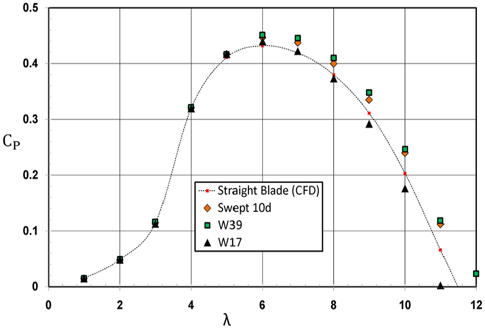
Comparison of power coefficient of cases W17 and W39, swept blade 10d, and the baseline straight blade.
By comparing the pressure contours on the pressure sides, in Figure 10, of the superior blades, W17 and W39. Meaningful differences at the winglet part and at the tip can be observed. The pressure near the leading edge at the tip of W39 blade is around 3600 Pa, while the pressure near the leading edge of the W17 blade is around 2000 Pa, this might be because the upstream direction is subject to more stagnation effect than the downstream blade. In addition, it is easy to notice that the pressure near the center at the tip of the W17 blade, at the winglet part, is less than that at the same position for the W39 blade. This makes the flow over the pressure side smoother for the W39 blade.

Pressure contours on the pressure side of (a) W17 and (b) W39 blades.
Figure 11 shows the pressure contours on the suction sides of both W17 and W39 blades. The pressure at the tip of W39 blade is higher than that at the tip of W17 blade. This is because, the W39 winglet is directed upstream and bends against the flow direction. On the other hand, a low-pressure region exists below the tip, at the winglet part, of W17 blade. The W17 winglet is directed downstream which subjects the flow over the suction side to excessive vortex compared to the case of upstream winglet.

Pressure contours on the suction sides of (a) W17 and (b) W39 blades.
Figure 12 presents the 3D streamlines over the winglet for W17 and W39 blades. The vortex of the wake flow near the tip is less sever at W39 blade when compared to W17 blade because W39 winglet is directed upstream and has lower cant angle, and it is more steeper.

3D streamlines over the winglet for (a) W17 and (b) W39 blades.
Figure 13 presents the thrust coefficients at range of TSR from 1 to 12 of W17 and W39 cases compared with straight blade and downstream swept blade 10d. The differences between W17 and W39 are very small. For speed ratios less than 5, thrust coefficient is almost similar to that of the straight blade. For speed ratios higher than 5, the cases W17 and W19, show lower thrust coefficient than the original swept blade 10d. This shows that adding winglets to the swept blade could reduce the thrust coefficient as compared to the swept blade alone case.

Comparison of thrust coefficient of cases W17 and W39, swept blade 10d and baseline straight blade.
Conclusion
The flow through a HAWT with swept blades featuring winglet tip was determined numerically in this research to study the chance of increasing the power of wind turbine. The winglet geometry was altered according to the change of cant and twist angels. Winglets pointing to pressure and suction sides were also taken into consideration in this study. A total of 51 winglet blades were created and examined in this study. By virtue of the obtained results in this research, it can be conclude that:
The performance study of the baseline straight and swept blades with winglet indicated that the use of winglet could enhance the wind turbine performance.
The best winglet was found with downstream swept blades and pointing to pressure side with a cant angle 40° and twist angle 10°.
Winglet leads to an increase in the output power of swept blades at speed ratios higher or equal to the design value (TSR = 6).
Use of winglets reduced the thrust coefficient as compared to straight and swept blade cases.
In this study, the effect of cant and twist angles were considered, while other parameters of the winglet (such as geometrical section, height, sweep, and toe angles) certainly affect its performance. A continuation work is planned to be carried out to get the optimum design of the winglet.
Footnotes
Handling Editor: Ahmed Abdel Gawad
Declaration of conflicting interests
The author(s) declared no potential conflicts of interest with respect to the research, authorship, and/or publication of this article.
Funding
The author(s) received no financial support for the research, authorship, and/or publication of this article.