
Abstract
To elucidate the vibration principle and effectively mitigate noise during power shifting in an automatic transmission, this study investigates a power split automatic transmission. The transmission principle and power flow path are analyzed using the centralized mass method and Lagrange equation. A vibration model that encompasses both clutches and gears is established for the coupling system. The dynamic model and vibration principle of clutches during power shifting are determined. Subsequently, the dynamic vibration characteristics are solved considering engine speed as a time-domain excitation source, while analyzing the dynamic transmission error. By optimizing gear modification parameters and structural stiffness, measures to reduce both dynamic transmission error and vibrational response during power shifting are obtained. Through vehicle-based vibration analysis and testing, a comparison is made between optimized gear parameters’ vibrational response characteristics and noise test data; revealing significant improvement in vibration performance by 3%–6%. A new approach is suggested for studying the vibration characteristics and dynamic response of automatic transmissions during power shifting, which provides both theoretical importance and practical benefit in effectively minimizing vehicle vibrations and noise.
Keywords
Introduction
Automatic transmissions satisfy the demands of dynamic performance, driving comfort, and improved vibration and noise performance. 1 The shifting elements in the transmission system establish specific kinematic relationships and gear ratios by connecting gear elements to each other or to the transmission housing. 2 The clutch plays a crucial role in the dynamic behavior of the transmission system, necessitating an accurate theoretical approximation of these components. 3 It is important that gears shift without power interruption, barely detectable by the driver. Vehicle comfort includes driving comfort as well as vibration and noise.4,5 The quality of transmission noise is mainly determined by the mechanical gear system. 6 An automatic transmission system is made up of parallel-axis gears, wet clutches, power-split planetary gear sets, and shaft rotors. Multiple parallel spur gears and planetary gears will engage in a gear condition, and a gear or planetary gear may also be engaged in many gears. 7 The power of an automatic transmission is not interrupted during shifting, and the speed and force of each component are subject to dynamic change, so the vibration response of shifting is a dynamic change. 8 Due to complex vibration principles and challenging noise control during shifting processes, no comprehensive theory or method has yet resolved the issue of vibration and noise in automatic transmissions.
Extensive research has been carried out on the vibration characteristics of gear systems to improve the vibration and noise performance of vehicles. Li et al. 9 analyzed the torsional vibration caused by clutch and gear sets in automatic transmissions, predicted the magnitude of vibrations in transmission systems through powertrain simulation during clutch meshing process, and identified key factors contributing to noise generation. Chen 10 analyzed the vibration of electric buses during acceleration and shifting and used three methods to control vibration and noise. The results showed that the suggested logic control strategy successfully diminishes structural vibrations and enhances driver comfort according to the findings. Zhang et al. 11 proposed a finite element analysis method for planetary gear sets with four degrees of freedom in automatic transmissions. They developed a dynamic model specifically for passenger cars to simulate transient torsional vibrations, free vibrations, as well as 2–3 gear shifting-induced vibrations during acceleration. Jo et al. 12 established a dynamic model of the powertrain of a rear-wheel-drive passenger car, analyzed the vibration of 1–2, 2–3, and 3–4 shift gears, and experimentally compared the results. Lin et al. 13 developed contact and friction models to characterize contact forces during gearshift processes, as direct observation was challenging. Zhang et al. 14 constructed a rigid-system vibration model for powertrains in automatic rear-wheel-drive passenger cars specifically simulating 1–2 shifting. Crowther and Zhang 15 formulated a torsional spring-mass model for transmission systems capturing transient vibrations experienced while shifting gears. Yan et al. 16 described the excitation and suppression relationships associated with the teeth number, harmonic order, and coupling vibration of the coupled system. Guo et al. 17 established a longitudinal-vertical coupled dynamic model of the DCT vehicle considering the powertrain mount. Liu et al. 18 developed a mathematical model of the coupled vibration between the drive shaft and the main reducer. They described powertrains as equivalent gear systems utilizing torsion elements along with concentrated mass.
These results involve the vibration of automatic transmissions during shifting. Three points require attention:
Existing research predominantly focuses on vibration and noise analysis for individual gear pairs, with limited investigation into compound gear sets;
The majority of studies concentrate on vibrations in transmissions featuring a single speed ratio, while comprehensive examination of vibrations in transmissions with multiple speed ratios remains scarce;
Research primarily emphasizes the impact of vibrations during gear shifting, neglecting dynamic vibration characteristics and responses exhibited by automatic transmissions during power shifting.
This paper studies the vibration principle of an automatic transmission during power shifting and a method to control its vibration and noise. Taking an eight-speed automatic transmission as the research object,19,20 we analyze the power flow rate of the transmission system and the operation mechanism of the clutches during shifting. Subsequently, we establish a dynamic vibration model for automatic transmissions equipped with power-shifting capabilities and assess how clutch engagement/disengagement affects vibrational characteristics. Through optimization of gear modification parameters and structural stiffness, we identify measures to mitigate dynamic transmission errors and minimize vibrational responses encountered during power shifting events. Experimental validation is carried out to confirm the effectiveness of the proposed solutions. Ultimately, this paper presents an integrated theoretical-practical design approach encompassing both vibration analysis techniques and effective noise control strategies tailored specifically for automatic transmissions undergoing power shifts.
Dynamics of automatic transmission
Gear system
The structural principle of the transmission being studied is demonstrated in Figure 1. It consists of three parallel-axis spur gear pairs, three planetary gear sets, and five multi-plate wet shifting elements connecting two parallel axes. The first axis incorporates the initial planetary gear set (P1), which divides the input power to drive the pinion gears of three parallel-axis spur gear pairs (G5 and G8, G4 and G7, G6 and G10). This arrangement establishes three distinct paths for power flow from the first to the second axis. On the second axis, we find both the second and third planetary gear sets (P2 and P3). Positioned between this axis and the output axis are final gears – G2 on the second axis itself, while G11 connects with the differential housing. By transferring power to the output shaft through these components, speed imbalances between two wheels can be effectively balanced by means of differential housing functionality. Corresponding gears or housing connect all five shifting elements together. Brake B1 as well as clutch C1, clutch C3, and clutch C4 are located on the first axis; clutch C2 is situated on the second axis instead. In each gear speed configuration, three shifters remain closed while two others open accordingly. We manipulate clutch engagement status to achieve desired transmission ratios by following a shift logic outlined in Table 1.
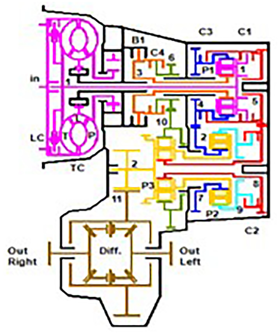
Illustrates the structural principle of an 8-speed automatic transmission.
Shift logic.
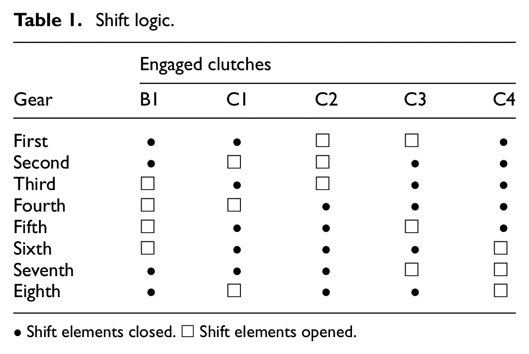
• Shift elements closed. □ Shift elements opened.
Model of clutch
Principle of clutch
The process of changing gears in an automatic transmission involves one clutch opening and another clutch closing. As shown in Figure 2, the closed clutch keeps the transfer torque, but the pressure drops until the other clutch closes fully and takes the torque. We control the clutch opening or closing by the clutch pressure and define the shift point as that when the opening and closing clutches have the same torque. During shifting, all shift operations in the transmission have an overlapping phase to maintain continuous power delivery.
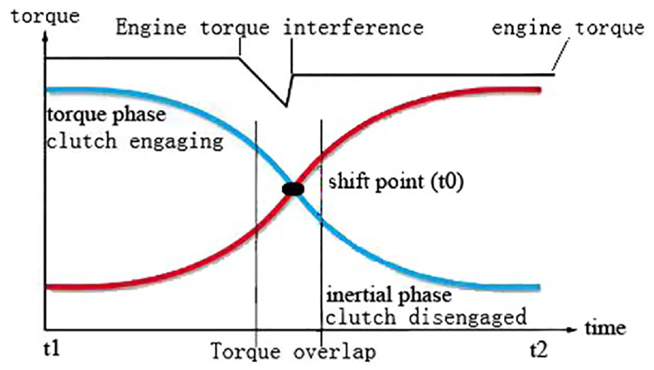
Clutch control during shifting.
Gear shifts include up and down shifts. The transmission’s shifting process has been simplified to an equivalent fixed gear train model, defined by the input and output shafts as illustrated in Figure 3.
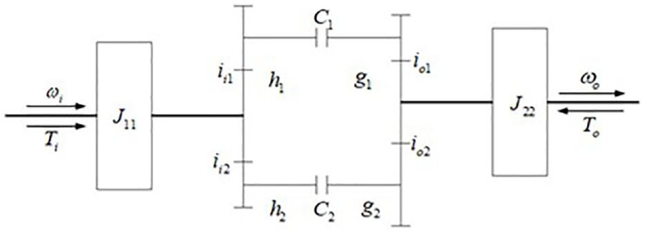
Equivalent model of shift clutches.
As shown in Figure 3, C1 and C2 stand for clutches;
Assuming that both C1 and C2 are disengaged simultaneously, at this point, gear drive system has two degrees of freedom. The generalized speed coordinate is set as angular velocities for input and output shafts respectively. Then, the angular speed of any component j in the gear transmission system is as follows:

where
Mechanical model of clutch shifting
The ratio of the input and output gear pairs is
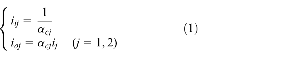
where
The clutch transmits torque equaling product between normal force on clutch friction plate and its friction coefficient; where normal force equals pressure multiplied by piston’s friction area. Gear shifting process involves filling specified clutch with oil from hydraulic system gradually compressing its friction plate thereby changing motion state.
Kinetic energy of system
As shown in formula (1), if linear relationship exists between any component’s speed
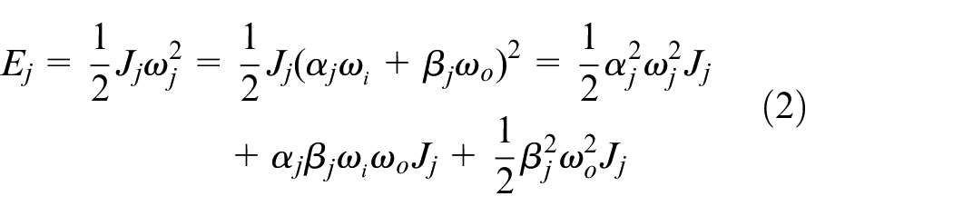
Therefore, the overall kinetic energy of the system is:
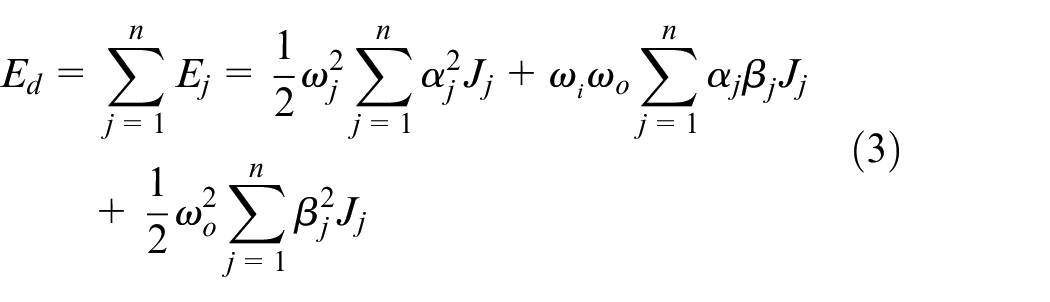
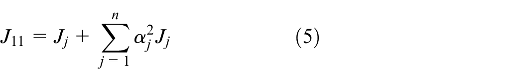
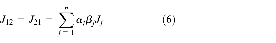
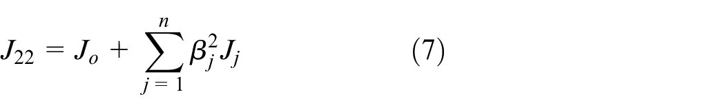
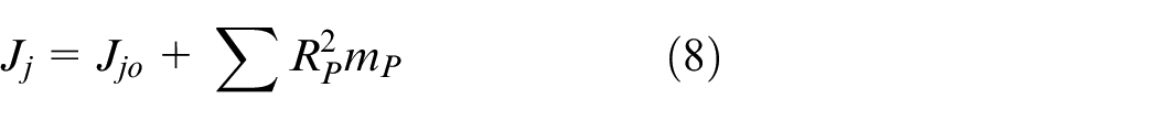
If the moment of inertia
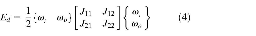
where
where
Where
Generalized force of system
The generalized force of the system is obtained by applying the principle of virtual displacement (energy equivalence), with the angular displacement of input and output shafts as generalized coordinates.
The sum of the virtual work done by all the forces in the system is

Where
The virtual displacement of the clutch is:
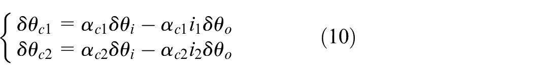
where
Combining (9) with (10), we obtain
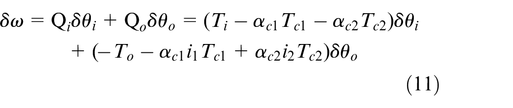
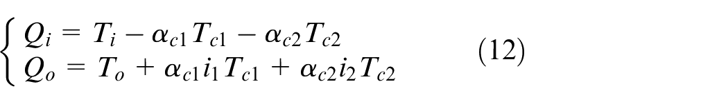
Thus, the system has two generalized forces available.
Dynamic model of system
The Lagrange equation is used to build the model, because the kinetic and potential energies do not follow the change of the generalized coordinates. Dissipative energy typically refers to the energy loss in a system caused by factors such as frictional forces. This aspect will not be considered in this article.
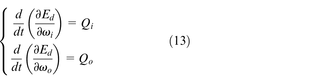
Combining (13) with (4) and (12), we obtain
where
Vibration principle of gear systemin automatic transmission
Calculation of input torque
The mathematical model for engine torque is defined through a function that considers engine speed and throttle opening.

where
We simplify the part from engine to clutch to a mass-spring-damped (MSD) system:


where formula (16) represents the stiffness characteristics of the component, and T1 is the torque of each component; formula (17) represents the damping properties of the component, and T2 is the rotational resistance; and formula (18) represents the inertia characteristics of the component, and T3 is the torque used to change the speed of the transmission shaft.
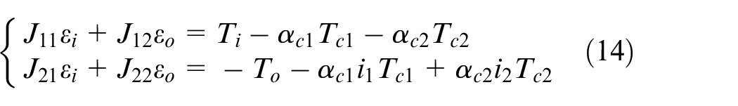
Therefore, when the clutch is in a slipping state, its input torque is:

Vibration differential equations of structures
Several components are implicated in the transition process during analysis of the model. In order to ensure fast and precise calculations, the engine housing is considered a rigid component, meaning the junctions with bearings and mounting points have no degrees of freedom. The equilibrium condition of the node can be utilized to derive the dynamic equation of the structure. Assuming that a node has n degrees of freedom, n dynamic equilibrium equations can be established for the node, with general form:
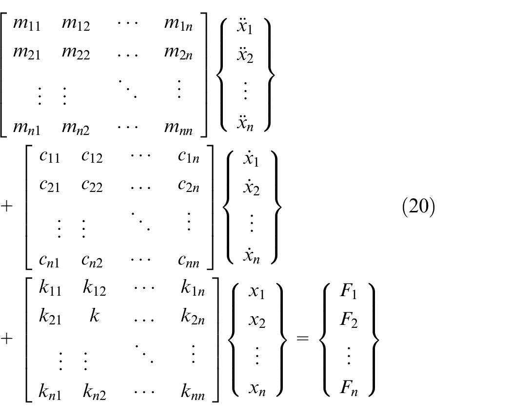
If the dynamic equations of all nodes are combined, the dynamic equations of the structure can be obtained, which can be represented in matrix notation as

where
Based on the shift theory, the simulation model of the shift process of the powertrain is built using multi-body analysis software. The torque converter serves to dampen engine vibrations rather than increase torque. The model depicted in Figure 4 features the engine, torque converter, and automatic transmission, with the torque converter being in a closed state. The transmission includes three sets of external gears: G58, G47, and G610.
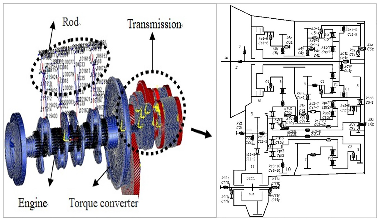
Multi-body dynamic model of shifting process.
The primary moving components of the powertrain transmission system are analyzed through finite element modeling and simplification. The output torque of the engine is defined to vary sinusoidally, and the transmission gear is connected to the support shafts through a concentrated mass point.
Analysis of vibration during shifting
Using formula (21), the vibration differential equation of the shifting process is established, with D2 up to D3 as an example, where the power flow path of the transmission under D2 and D3 gears is shown in Figure 5.
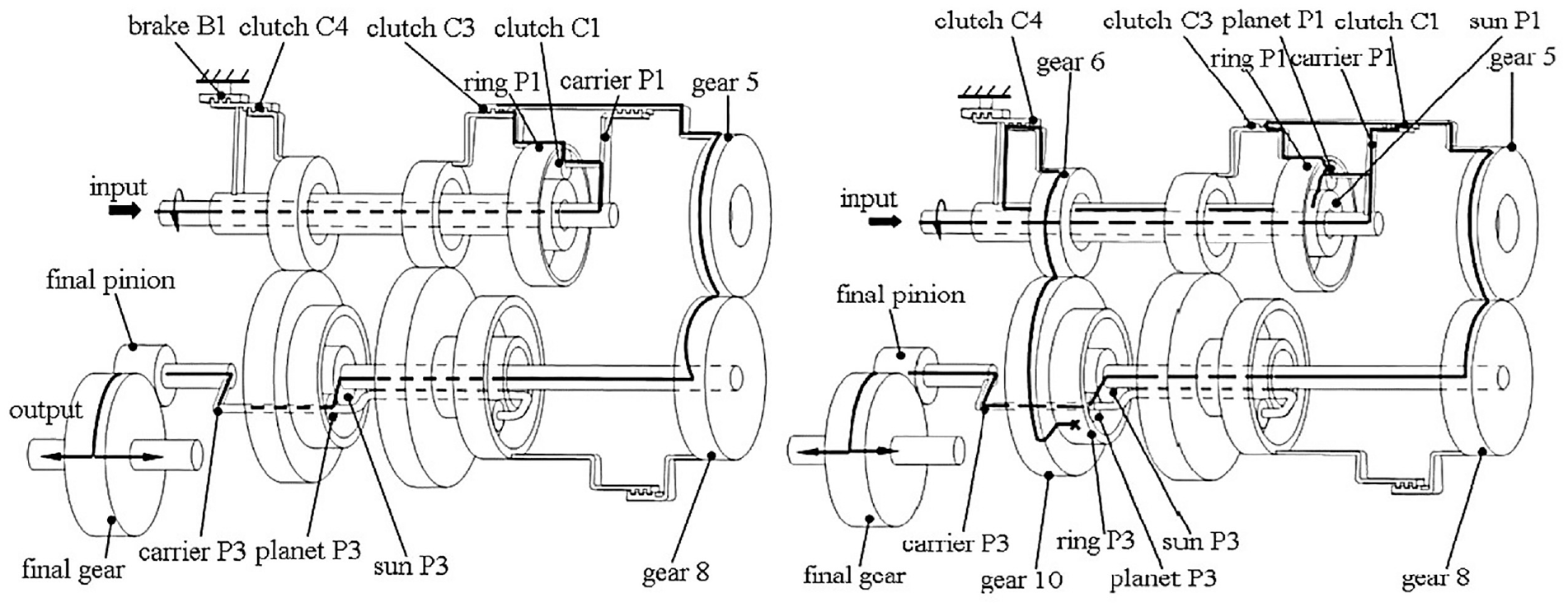
Shows the power flow path of transmission in D2 and D3 gears.
For the vibration analysis of shift gears, the power flow paths of D2 and D3 gears are compared:
During the shift from path D2 to D3, B1 opens gradually, and the C1 clutch, parallel to C3, closes gradually. It is assumed that the translational vibration direction of G5 is positive, and its generalized displacement array is
The B1 brake in series with C4 is closed gradually, and its generalized displacement array is
where,
Differential equation of vibration during shifting
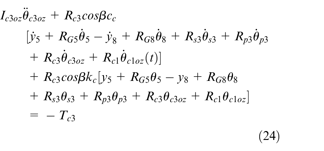
The process of gear shifting involves conversion between torque and inertia phases through continuous increase in pressure on one clutch while decreasing pressure on another. Based on differential equation describing clutch vibrations, torsional vibration equation is derived for outer housing of C3 clutch during gear shifting (
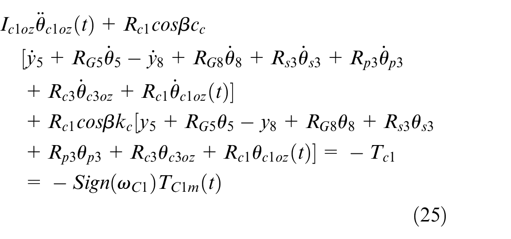
The torsional vibration equation for the outer housing of the C1 clutch is:
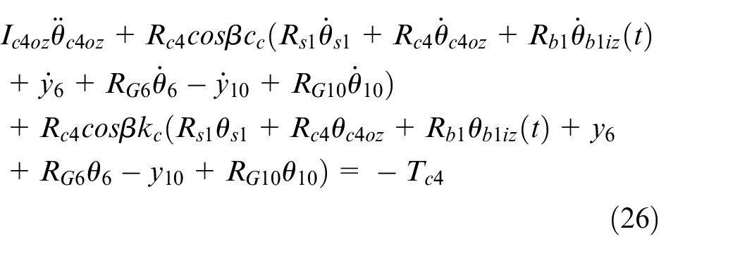
The equation for the torsional vibration of the outer housing of the C4:
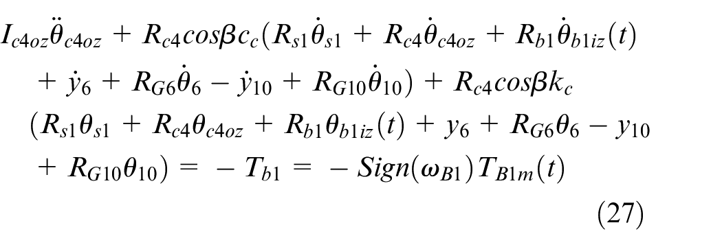
The torsional vibration equation of the inner hub of brake B1 is:
where
Vibration characteristics of power shifting
The dynamic attributes of gear shifting encompass the speed, torque, and acceleration of every rotating component within the transmission. All the gear shifts of the 8AT during acceleration and braking were studied. For a certain pair of gears in the transmission, there will be a most important shift process, the typical process D2–D3 is selected for illustration. Because D2:D3 process includes multiple power flow paths of the transmission, which is the most complex gear in the working condition, and the noise of D2:D3 process is also the most obvious during the vehicle test. All downshifts including d3:d2 were studied. The vibration research method of downshift process is similar to that of upshift, except that the force on the other side of the gear tooth surface is applied. The result is similar, so there’s no repetition here.
Speed analysis
The shift request is made by transmission control unit (TCU)using shift control strategy along with decrease in engine speed and transmission input shaft speed while smoothly increasing output shaft speed. Figure 6 shows the speeds measured at both the transmission input and output shafts during the engagement of D2 gears from 0 to 0.6 s, and the subsequent transition to D3 gears from 1.2 to 2.0 s. The change from D2 to D3 gears takes place between 0.6 and 1.2 s, during which the engine speed drops from 1520 rpm with D2 gears to 1190 rpm with D3 gears. Throughout this transition, the speed of the output shaft steadily rises from 650 to 730 rpm.
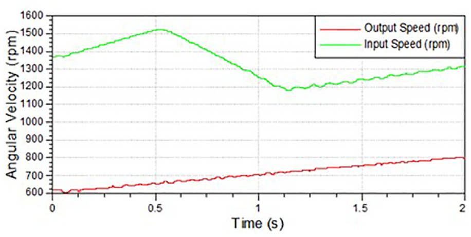
Speed of transmission input and output shafts.
During the shifting process, the vehicle’s load remains constant while the output speed steadily rises. During shifting, both the transmission ratio and the transmission speed decrease. The rotation speed increases after shifting.
Torque analysis
As shown in Figure 7, the B1 clutch is engaged before the gear is shifted. The C1 clutch gradually engages, transferring torque when the gear shift initiates at 0.6 s. Simultaneously, the B1 brake gradually disengages, resulting in a decrease in transmitted torque. As the clamping force of the B1 clutch decreases, the C1 clutch fully transfers torque at 1.4 s while the B1 clutch transfers zero torque.
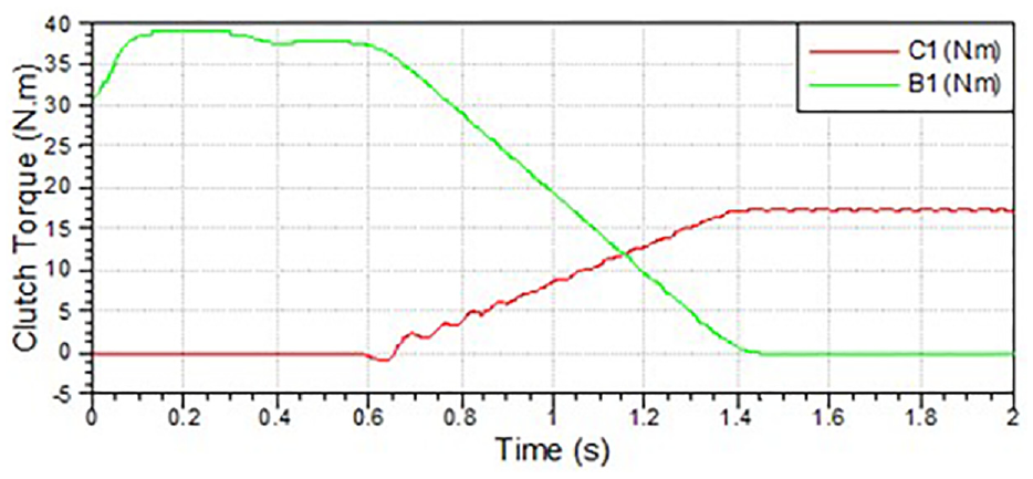
Torque of clutches during shifting.
Force analysis
In different gears, meshing gears exhibit varying statuses and transfer different amounts of torque. The vibration of the shifting process comes from the force fluctuation. Figures 8 and 9 illustrate forces acting on gears G58 and G610 respectively along x, y, and z directions during gear shifting; where x represents radial direction, y represents tangential direction, and z represents axial direction.
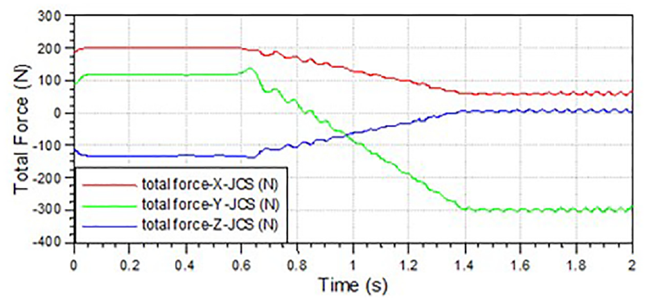
Force of gear G58 during gear shifting.
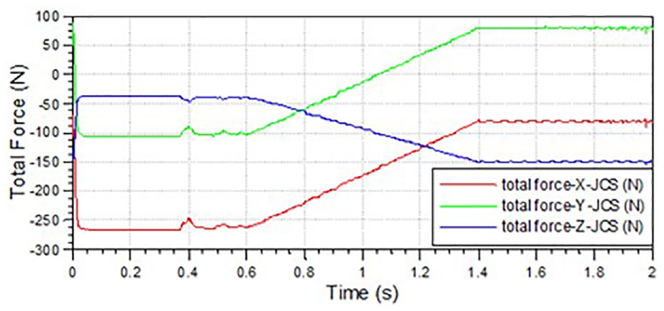
Force of gear G610 during gear shifting.
As shown in Figures 8 and 9, the forces exerted by G58 and G610 are relatively stable at the D2 speed, and force fluctuation is obvious at the D3 speed. In the shift process, the force vibration of G58 in three directions is large, and the vibration of G610 is relatively gentle. If the force fluctuation of a gear is obvious, there may be a noise problem.
Acceleration analysis
Vibration acceleration and transmission error in the time domain can be used to characterize the vibration noise level of a gear. A larger amplitude of acceleration vibration will lead to a larger transmission error of the gear, as shown in Figures 10 and 11, which show the curves of acceleration vibration for the support shaft of G58 in the respective radial and axial directions.
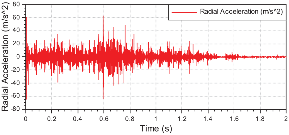
Acceleration vibration in the radial direction of gear G58.
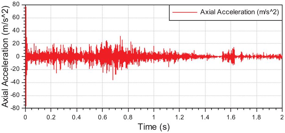
The axial acceleration vibration of gear G58.
When shifting gears, the clutch’s mechanical state changes, causing significant acceleration changes in the support shaft of the gear, leading to similar acceleration in the gear. To reduce the dynamic transmission error of gear meshing, measures should be taken to reduce the amplitude of radial acceleration.
Dynamic transmission error
In addition to meshing stiffness, dynamic transmission error is affected by the fluctuation of the engine crankshaft speed, whose meshing impact is much larger than that of the transmission error. The transmission error curves for gears G58 and G610 during shifting can be observed in Figures 12 and 13, respectively. The transmission runs in D2 gears from 0 to 0.2 s and in D3 gears from 0.8 to 1.0 s, and the transmission shifts from D2 to D3 gears from 0.2 to 1.0 s.
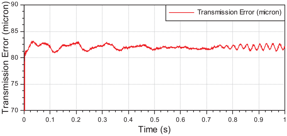
Dynamic transmission error curves of gear G58 during shifting.
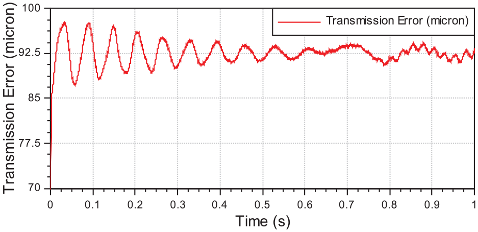
Dynamic transmission error curves of gear G610 during shifting.
The dynamic transmission errors of G58 and G610 under gears D2 and D3 exhibit distinct characteristics, as depicted in Figures 12 and 13. In the D2 gear position, the impact of gear-induced transmission error fluctuations is relatively minor compared to the influence of engine speed fluctuations. Conversely, in the D3 gear position, the transmission error of G610 is primarily influenced by its own gear characteristics rather than engine speed fluctuations. On the other hand, for G58, its transmission error is less affected by its own gear characteristics but significantly impacted by engine speed fluctuations. During the shift process from D2 to D3, when two pairs of meshing gears are engaged through clutch connection, dynamic transmission errors are less susceptible to engine speed fluctuations but more influenced by their inherent properties.
Dynamic response and control of vibration
In order to reduce the vibration response of the system, we identified the best design for modifying the gear profile and adjusting the support stiffness. The professional gear calculation tool was employed to carry out the optimal design of gear profile modification, and by incorporating the design results into the model during shifting process, we calculated the transmission error of the gear. Regarding the support stiffness of a transmission gear, it was adjusted based on the vibration equation in order to alter the dynamic vibration characteristic of the system.
Effect of profile modification on dynamic transmission error
Taking G610 in the transmission as our research subject, we investigated its transmission error under different modification parameters in time domain analysis. We examined the impact of adjustments on transmission errors during shifting.
Modification
To verify the effect of G6 profile modification on transmission error in the time domain, two cases are set, as shown in Table 2, where parameters in case 1 carries out no modification to G6; The optimization parameters of Case 2 were obtained by using the special gear analysis tool Romax and genetic algorithm. In genetic algorithm, the micro-modification parameters are defined as design variables, and the transmission error is defined as the objective function. After many iterations, the optimal micro-modification parameters of G6 are obtained.
Two cases of G6 profile modification.
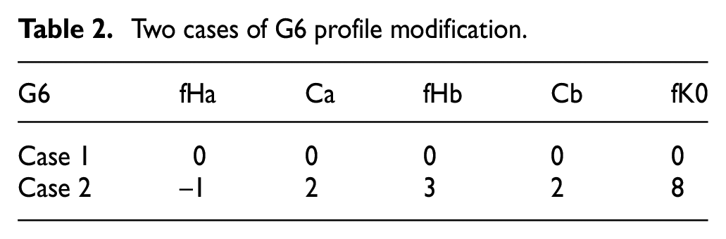
Where, fHa is tooth profile shape deviation; Ca is deviation of drum shape of tooth profile; fHb is tooth shape deviation; Cb is deviation of tooth drum shape; fKo is top trim of tooth.
Dynamic transmission error
Figure 14 illustrates two cases (red line: case 1; green line: case 2) depicting dynamic transmission errors for gear G610 during gear shifting. The x coordinate represents rotation angle of engine crankshaft (0°–1200° corresponds to D2 gear, 4800°–6000° corresponds to D3 gear, and middle region indicates shift process).
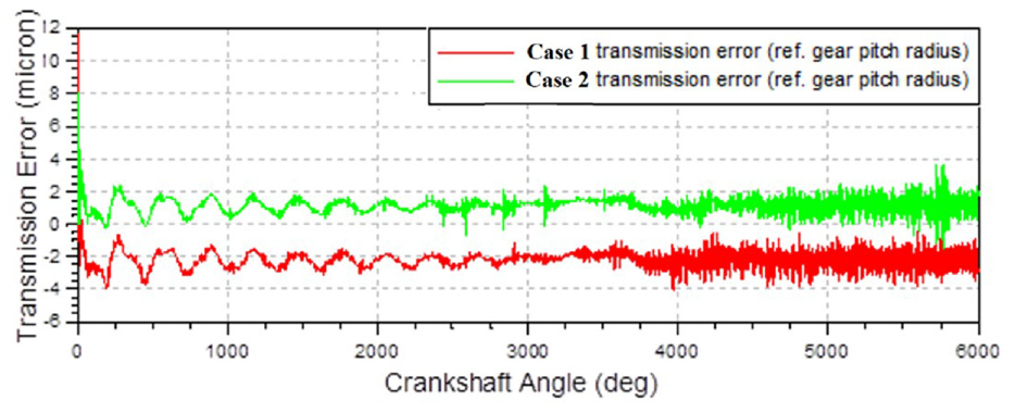
The dynamic transmission error of gear G610 in two different scenarios.
After the modification of G610, the magnitude of transmission error in the time domain changes little in the whole gear shifting process, but the band of dynamic transmission error moves from range (–2, –4) to range (0, 2).
Effect of support stiffness on dynamic transmission error
Taking gear P1 in the transmission as the research object, the transmission error under different support stiffness is studied in the time domain, and the influence of support stiffness on transmission errors is analyzed during shifting.
Support stiffness
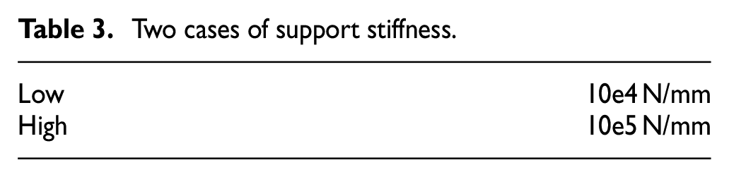
To verify the effect of support stiffness on transmission error in the time domain, two cases are set, as shown in Table 3.
Two cases of support stiffness.
Dynamic transmission error
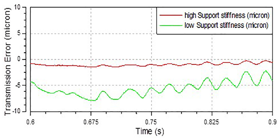
Figure 15 shows the transmission error of gear P1 under different support stiffness (green curve: less support stiffness; red curve: more support stiffness).
Dynamic transmission error of gear G58 under two cases.
After reinforcing the support stiffness, the dynamic transmission error during gear shifting is decreased from 7 to 1 µm, resulting in a significant reduction in fluctuation amplitude. This is akin to the transmission error acquired when enhancing meshing stiffness through profile adjustments. We have studied the transmission errors of 7 upshifts and downshifts. We also compare and analyze the error of all shifting after increasing the support stiffness, and no obvious gear shift whistling were found.
Test verification
The test of the vehicle is carried out on the road. In the WLTC cycle test, we tested several driving cycles, and the experimental car made a whine during the previous D2–D3 shift process, which seriously affected the driving experience of the vehicle, so the paper chose D2–D3 gear to describe. Figure 16 displays vibration test results conducted on a vehicle’s transmission with a vibration acceleration sensor placed at position corresponding to each respective gears’ location for signal acquisition. The accelerometer is a three-phase vibration accelerometer. The test signal of the acceleration sensor can be decomposed into signals in three directions x-y-z. Key equipment parameters are as follows:
Maximum sampling frequency: 102.4 kHz.
Channels: 16.
Accuracy: 24 bits.
Maximum bandwidth: 40 kHz.
Phase accuracy: less than 0.2° at 10 kHz.
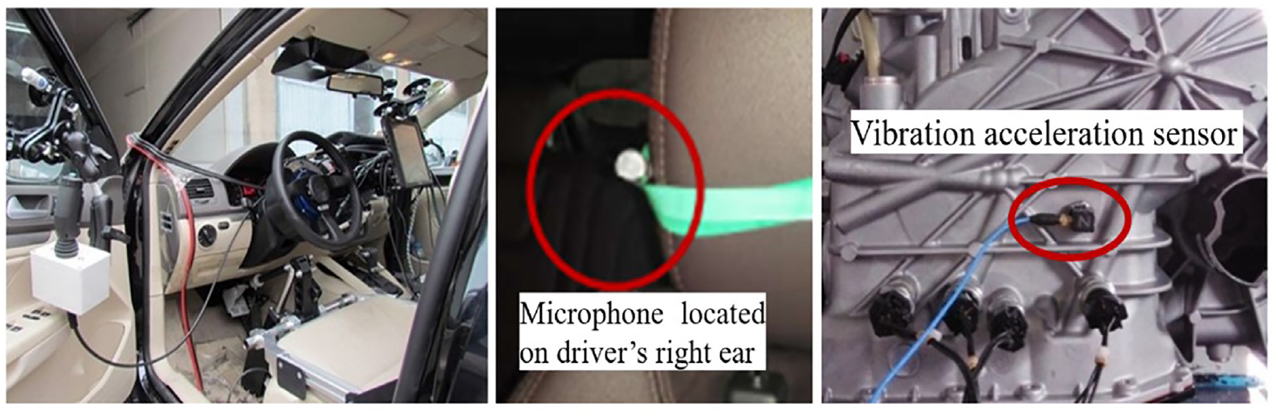
Vibration test of the transmission in a vehicle.
Figure 17 shows the color map and sound pressure level of vibration before and after optimization for gears G58 and P1 during the D2–D3 phase. Figure 17 shows the frequency domain analysis of the test results. The horizontal coordinate is frequency. The gear meshing frequency is different in different gear positions. The time to start shifting is when the frequency of the vibration curve changes.
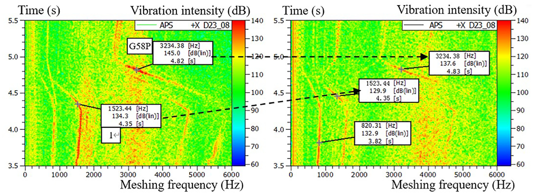
The noise is improved by optimizing gear modification and structural stiffness.
The values of vibration of gears G58 and P1 decreased by 7.4 and 4.4 dB, respectively, during the shift, and it was found that the noise could be improved by 3%–6% by optimizing gear modification parameters and structural stiffness.
Conclusions
This study elucidated the vibration principle of an automatic transmission during power shifting and derived an effective approach to control the vibration and noise of a transmission system. The following conclusions were drawn:
A comprehensive model was established for the compound gear train, encompassing clutch switching and power shifting, enabling investigation into the dynamic response of power shifting;
The dynamic characteristics and transmission errors of gears during power shifting were analyzed, leading to insights into the system’s vibration response;
Vibration reduction and noise improvement were achieved by improving gear tooth shape modification and support stiffness, which was verified by tests, and noise reduction was improved by 3%–6%.
An integrated analysis method was developed for investigating the vibration characteristics and dynamic response of an automatic transmission during power shifting, which holds significant implications for dynamic vibration response analysis while effectively mitigating vehicle vibrations and noise.
Footnotes
Declaration of conflicting interests
The author(s) declared no potential conflicts of interest with respect to the research, authorship, and/or publication of this article.
Funding
The author(s) disclosed receipt of the following financial support for the research, authorship, and/or publication of this article: This work is supported by the Talent Fund of Beijing Jiaotong University (V23XKRC00040).
Data availability statement
All relevant data are within the paper.