
Abstract
The increasing applications of flexible parallel robots in industrial production have presented the advantages of light weight and high speed, but at the same time, the elastic vibration problem has emerged. By investigating the modal features of flexible parallel robots so as to suppress the elastic vibration, with pinned-pinned as flexible intermediate links boundary conditions, this article analyzes the rigid-flexible coupling dynamic mathematical model of the 3-RRR (3-Rotate-Rotate-Rotate) flexible planar parallel robot with flexible intermediate links. The effect of the extremity concentrated rotation inertia of flexible intermediate links is considered in the mathematical model. Besides, the effect of inertia and coupling force on the dynamic model and the first three-order vibration responses of flexible intermediate links were discussed based on the established model. The corresponding spectrum characteristics were studied using fast Fourier transform. Comparing the frequency characteristics obtained by theoretical model and modal experiment, it was found that the results obtained by the dynamic mathematical model are quite close to the test results. Less dynamic parameters make it convenient to carry out the control program.
Keywords
Introduction
Compared with the serial robots, parallel robots possess a lot of advantages such as high speed and acceleration, heavy load capacity, low energy consumption, no cumulative error, and precise accuracy, which are widely used in aerospace, precision optical instruments, real-time high-precision measuring instruments, precision machine tools, and other fields.1–4
As the society advances, the development of the global mechanical products follow the way of high speed and efficiency as well as light weight with low power consumption. In the industrial application, the high stiffness and the large power consumption of the traditional series robot lead to the problem of too heavy structure. Therefore, the flexible parallel robots with high speed and efficiency, light weight as well as low consumption draw more and more attention. However, when the flexible parallel robots operate with loads at a high speed, due to the inertia force and other factors, the elastic deformation of the flexible intermediate links (FILs) is prone to occur, resulting in a declining dynamic performance of the robot, thus the normal work will be also affected. Therefore, the research of flexible parallel robots’ elastic vibration has become an urgent issue. At present, dynamic modeling and vibration suppression of the flexible bodies have received considerable attention.5,6 Regrettably, most of the published works in this area addressed the single flexible beam.7–10 The research works on the flexible parallel robots which are rather few. As rigid unit movement can cause the flexible components’ deformation, and flexible deformation can also influence the rigid unit movement, the system dynamic model of flexible parallel robots is much more complex than that of rigid parallel robots. The dynamic model is nonlinear, rigid-flexible coupling, time-varying differential equations. 11
From the studies in recent decades, it shows that lumped parameter method (LPM),12,13 finite element method (FEM),14–16 and assumed mode method (AMM)17,18 are the common ways for rigid-flexible dynamic modeling. Wherein, the AMM is a dynamic modeling method which is more suitable for studying the modal characteristics. Different programs for dynamic modeling of flexible parallel robots have been studied. Han et al. 19 studied the influence of random errors on the motion of Stewart rigid-flexible coupled parallel platform by virtual simulation. In the study by Yang et al., 20 the flexible Stewart platform was taken as the research object, and the dynamics and control of the six-axis isolator were studied. KV Varalakshmi and J Srinivas 21 presented dynamic analysis studies of planar parallel flexible 3-RRR (3-Rotate-Rotate-Rotate) manipulator with and without considering the flexibility of mobile platform. The research results show that flexibility factors cannot be ignored. Zhu et al. 22 used the co-simulation method of ADAMS and ANSYS to propose the dynamic analysis of rigid-flexible coupling system of 3-TPT parallel robot in ADAMS and the stress analysis in ANSYS. Liu et al. 23 proposed a dynamic modeling and solving method for 3-RRS space parallel robots with flexible links. Wang et al. 24 analyzed the natural frequencies of the 3SPS + 1PS parallel hip manipulator based on the rigid-flexible coupling theory. Zhang et al.25,26 developed a dynamic model of 3-PRR flexible planar parallel robot (FPPR) with FILs. Chen et al. 27 showed an efficient dynamic modeling method for high-speed FPPR with FILs. A rigid-flexible dynamic model of the planar parallel manipulator was developed based on the extended Hamilton’s principle utilizing exact boundary conditions in Zhang et al. 28 The natural orthogonal complement was presented in the study by Ganesh and Rao 29 for the inverse dynamic analysis of 3-PRR FPPR. Yu et al. 30 verified the dynamic model of the flexible planar 3-RRR parallel robot through experimental study. It mainly focuses on kinematics analysis and motion control. Zhang and colleagues31,32 showed the impact of temperature on the dynamic model of the 3-RRR FPPR and established rigid-flexible coupled dynamics model of the system using FEM and compared with the dynamics without considering the rigid-flexible coupling. The results show that the rigid-flexible coupling is an indispensable consideration. The joint space impact on dynamic model of the 3-RRR FPPR is analyzed in Zhang et al. 33 Sheng et al. 34 established a simple and efficient dynamic model of the planar flexible parallel manipulator with the pinned-free boundary condition to study its dynamic characteristics. Liang et al. 35 presented a methodology to develop the rigid-flexible coupling dynamic model of an emerging flexible parallel manipulator with multiple actuation modes. The literature mentioned above only emphasizes the accuracy and ignores the simplicity of the model, leading to difficulties in model solving and controller design. Due to the coupling force and inertial force of the flexible parallel robot during operation, the flexible parallel robot is more prone to unstable vibrations compared with rigid robots. In order to clearly understand the dynamic characteristics of the flexible parallel robot and the coupling mechanism between flexible link and rigid link, the modal characteristics of flexible parallel robots are studied. In the design process, to avoid the resonance frequency of the system in advance, the elastic dynamics model needs further study.
Different with the references above, this article selects the 3-RRR FPPR with FILs as the research object. As the effect of rigid-flexible coupling is concerned, combined with the feature of the system structure, the modal function is determined with the pinned-pinned as boundary condition of the FIL. Then, based on the Lagrange equation and AMM, considering the main vibration modes of the system, a high-efficiency coupling dynamic model is established on the basis of guaranteeing the model control accuracy. The effect of the rotatory inertia caused by FIL ends to the coupling dynamic model and system modal characteristics are investigated based on the established theory model. Finally, the correctness of the theoretical model is verified by modal experiment. Less dynamic parameters of this model make it convenient to carry out the control program. The rigid-flexible dynamic model can better reflect the modal characteristics of the system and provide a reference for avoiding the resonant frequency during the design process.
This article is organized as follows: The second section describes the overview of the system object. Dynamic modeling process is reflected in the third part. The fourth part is the numerical simulation. Experimental verification is presented in the fifth part. The last part is the conclusions.
The system overview of the 3-RRR FPPR
The schematic diagram of 3-RRR planar parallel industrial robot is shown in Figure 1, which is composed of the moving platform C1C2C3 of a regular triangle, the fixed base A1A2A3 as well as three identical branches A1B1C1, A2B2C2, and A3B3C3. As the case in Figure 1, A1, A2, A3 are the three vertices of the regular triangle, where the active revolute joints are set. The points of B1, C1, B2, C2, B3, C3 are the passive revolute joints, where A1B1 = A2B2 = A3B3 = B1 C1 =B2 C2 = B3C3 = l = 210 mm. The diameter of the circle on the platform where joints are installed is D = 136 mm. The 3-DOF planar motion can be achieved using the three driving motors in the three active joints.

The structure diagram of the 3-RRR FPPR.
In some practical applications, the larger the size of the cross section of the driving link, the more rigid stiffness could be ensured. And as the FIL is equipped with a smaller cross-sectional area, more weight could be saved. Therefore, this article sees the FILs of the 3-RRR FPPRs as the flexible part and others as the rigid part. The vibration of mechanism is mainly caused by the driving motor, payload of the moving platform, and the inertia force. Suppose that little deformation occurs on the connecting link, the linear deformation by which it is modeled could be considered, compared with the longitudinal direction of the FIL. And the FIL can be supported as Euler–Bernoulli beam model which is pinned-pinned at the end. The fact that the bearing connects at the ends of the FIL may lead to concentrated rotational inertia and should be taken into account.
The coordinate system of the 3-RRR FPPR is shown in Figure 1, illustrating two states of the intermediate link, namely, the flexible and rigid states. Therefore, on the basis of the formulation of the AMM, the flexible deformation of the ith FIL can be expressed as follows


where

where qij represents the jth mode of the ith FIL.
The dynamic equations of the 3-RRR FPPR system
The dynamic equations of the 3-RRR FPPR can be derived based on AMM and Lagrange equation; therefore, the kinetic and potential energy of the system should be presented first. The total kinetic energy of the system includes the drive link kinetic energy, the FIL kinetic energy, and the moving platform kinetic energy. The drive link kinetic energy can be expressed as follows

Among them,
The FIL kinetic energy which considered the extremity concentrated rotation inertia of the FIL can be described as

The moving platform kinetic energy is given by
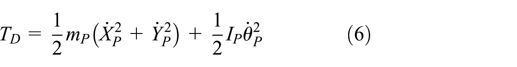
The total kinetic energy is

where
Since the 3-RRR FPPR moves in a horizontal direction, potential energy keeps unchanged. The system potential energy is caused only by deformation of the FIL, which can be expressed as

where
According to the Lagrange method, the system kinetic and potential energy is substituted into the second kind Lagrange equation

It can be written as
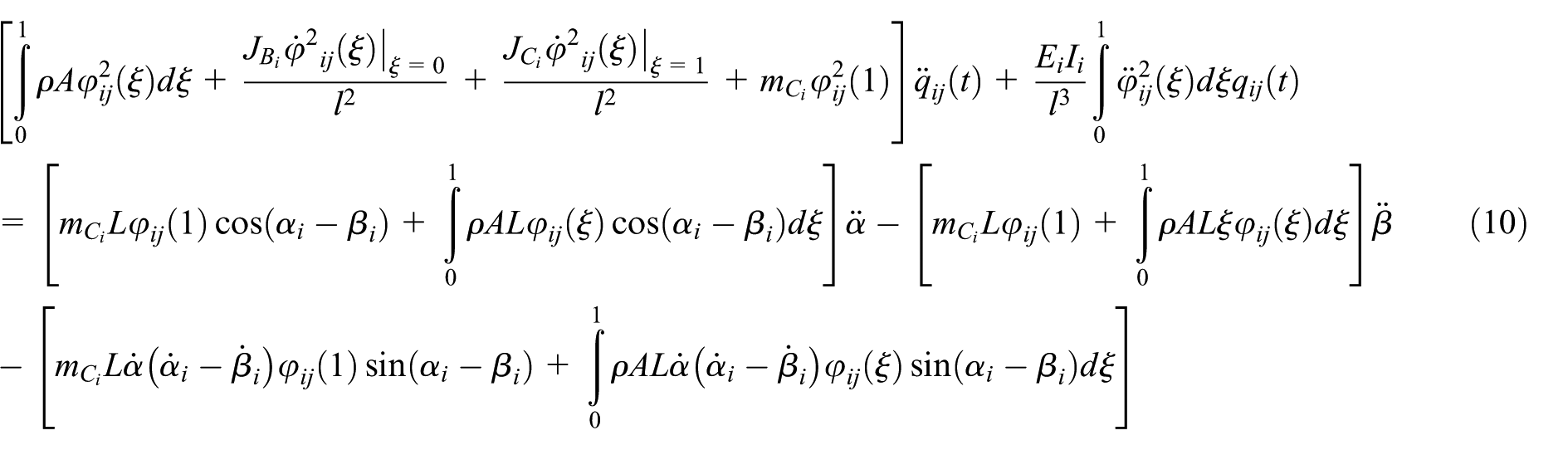
Equation (10) can be derived as follows

where M is the modal mass matrix. q serves as the flexible generalized coordinates. K is modal stiffness matrix. F is rigid motion modal force caused by the elastic vibration.
The dynamic response characteristics of the FIL are researched to lay the foundation for the subsequent vibration control.
The dynamic response equation is

Equation (12) can be rewritten as

The solution of the equation can presented as follows

Numerical simulation
The processing material of 3-RRR FPPR is aluminum alloy 7075. The elastic modulus of the material is

The first three elastic vibration deformation at midpoint of the first FIL.
As Figure 2 shows, the amplitude of the vibration response for the first FIL at the midpoint is obviously higher when taking the centralized rotational inertia into consideration than that without considering the centralized rotational inertia. Meanwhile, the amplitude on the first-order vibration response for the first FIL at the midpoint is significantly higher than that on the second- or third-order vibration response. Therefore, it is more meaningful and useful to study the characteristics on the first-order vibration. During the actual operation, the vibration is characterized by the vibration response of the FIL. To further study the vibration features so as to reduce the impact on the overall performance of the robot by a determining vibration frequency, the spectral characteristics of the first FIL by fast Fourier transform (FFT) are demonstrated in Figures 3 and 4. Figure 3 indicates the spectral characteristics of the first FIL in the case of considering the centralized rotational inertia. Figure 4 analyzes the spectral characteristics of the first FIL regardless of the centralized rotational inertia.

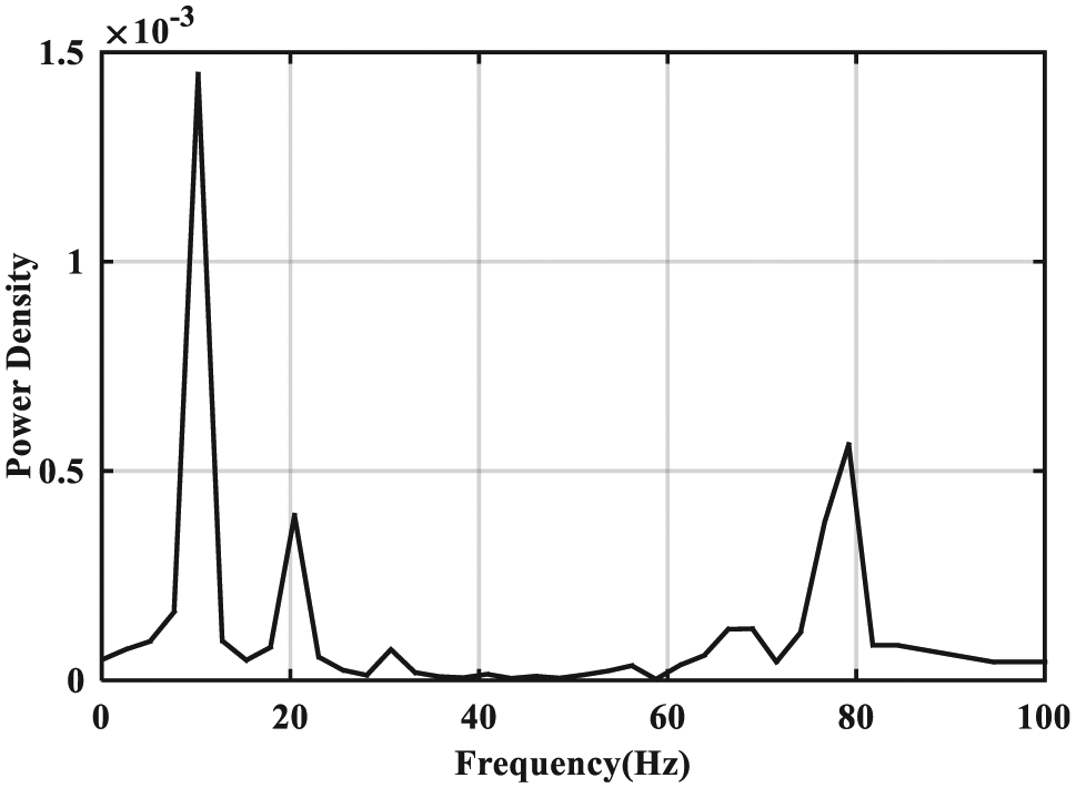
FFT of the first-order elastic vibration of the first FIL considering the centralized rotational inertia.
FFT of the first elastic vibration of the first FIL without considering the centralized rotational inertia.
As can be seen from Figure 3, given the centralized rotational inertia of the first FIL, the vibration frequency is mainly concentrated around 10, 20, 30, and 48.5 Hz. From Figure 4, it turns out that the vibration frequency is mainly close to 10, 20, 30, and 78.6 Hz when the centralized rotational inertia of the first FIL is set aside. According to equation (11), the first three-order free vibration frequencies of the first FIL with consideration of the centralized rotational inertia are 48.5, 212.6, and 304.3 Hz correspondingly. And when the centralized rotational inertia is not considered, the first three-order free vibration frequencies of the first FIL are 78.6, 393.6, and 792.9 Hz, respectively. From equation (11), it might also be found that both the inertial force and the coupling force can generate the vibration of the FIL. To further investigate the reasons for the frequency generator, the simulation results of the inertial force and the coupling force are illustrated in Figures 5 and 6, respectively.

The inertial force of the first FIL.

The coupling force of the first FIL.
The corresponding spectrum characteristics were studied using FFT. The spectral characteristics are shown in Figures 7 and 8.

FFT of the inertial force of the first FIL.

FFT of the coupling force of the first FIL.
Figure 7 demonstrates that the frequencies caused by the inertial force are 10, 20, and 30 Hz. Figure 8 reveals that the frequencies caused by the coupling force are 10, 20, and 30 Hz. Therefore, 10, 20, and 30 Hz are frequencies of forced vibration caused by inertial and coupling force. It also means the vibration frequency 48.5 Hz in Figure 3 is the natural vibration frequency when the centralized rotational inertia of the first FIL is considered. The vibration frequency 78.6 Hz in Figure 4 is the natural vibration frequency when the centralized rotational inertia of the first FIL is not considered.
Experimental modal test validation
Experimental modal analysis is essentially calculated by vibration test technology to determine the natural frequency, damping ratio, and mode shape of the system under test.
The basic principle of measurement is as follows: if the damping of mechanical system or structure is not particularly large, then when the excitation frequency is same as or similar to the natural frequency of the system under the external excitation, the system will show spikes due to resonance. 36
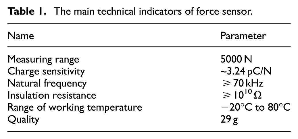
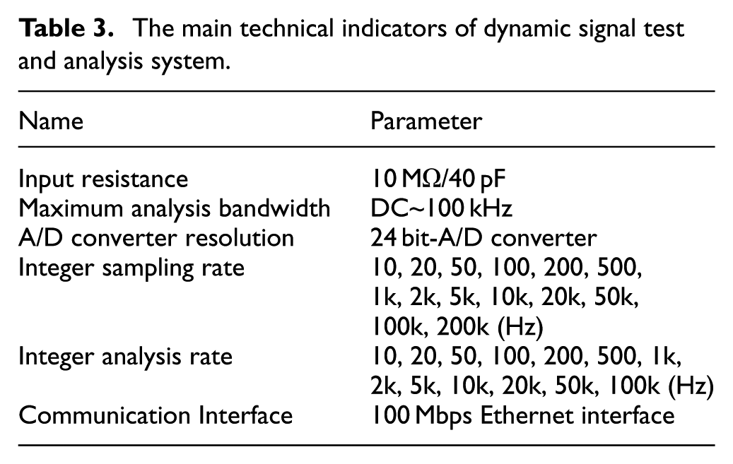
To verify the correctness of the dynamic mathematical model, the experimental equipment is set up as shown in Figure 9. The modal test system consists of a computer (including analysis software), force sensor, dynamic signal test and analysis system, charge optimal modulator, piezoelectric accelerometer, and the structure to be measured. The force sensor is mainly used to generate exciting force. The main parameters are shown in Table 1. The piezoelectric accelerometer is mainly used to pick up and measure excitation force. The main technical parameters are shown in Table 2. The charge optimal modulator is mainly used to match the type of accelerometer output signal and dynamic tester acceptance signal. The charge optimal modulator in this experiment is DH5857-1. The dynamic signal test and analysis system, with FFT function, is mainly used to process the response signal. The measured object’s natural frequency, damping ratio, and modal shape based on the analysis signal can be calculated. The main parameters are shown in Table 3. The measuring points are shown in Figure 10. A total of seven test points were set up, among which the measuring points 1 and 7 were at the pinned joints, so no measurement was made. Therefore, the main points to be measured are measuring points 2–7, and the distance between each two measuring points is 30 mm.
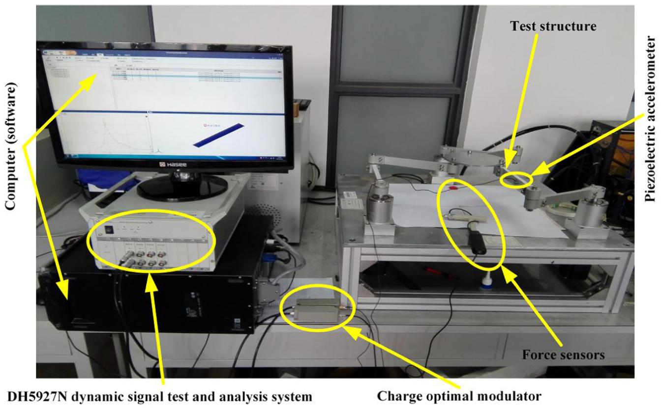
Modal experiment platform.
The main technical indicators of force sensor.
The main technical indicators of piezoelectric accelerometer.

The main technical indicators of dynamic signal test and analysis system.
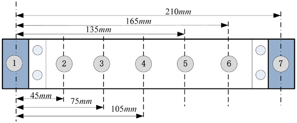
The distribution map of measuring point.
The experimental process is as follows: during the experiment, the three drive motors are fixed at the initial position, and the moving platform is placed at the center position. The multi-point excitation and the pick-up point test method are implemented. Since the measuring point 1 and the measuring point 7 are the pinned joints, the acceleration sensor is fixed at point 3 and the force sensor is used to hit from measuring point 2 to the measuring point 6, respectively. In order to achieve a more accurate result, the test is performed five times repeatedly and then the results are averaged. The test data are collected and recorded by the DH5927N dynamic tester. The dynamic response is analyzed by PolyLscf method, and the results are shown in Figure 11.

The results of vibration response.
The first-order frequency is 49.992 Hz, and the second-order vibration frequency is 277.813 Hz obtained through the analysis by PolyLscf method. The first-order frequency obtained by the theoretical model given in equation (11) is quite close to the test results. As shown in Figure 11, the true vibration characteristics of the 3-RRR FPPRs are reflected by the dynamic model established by considering the centralized rotational inertia in this article.
Conclusion
Based on AMM and Lagrange equation, the rigid-flexible coupling dynamic model of the 3-RRR FPPR is established with pinned-pinned boundary condition. The effect of the extremity concentrated rotation inertia of FILs and the modal characteristics of the 3-RRR FPPR are analyzed based on the established mathematical model. Through the contrastive analysis of modal characteristics obtained by theoretical model and modal experiment, the key findings of this work are summarized as follows:
The centralized rotational inertia of the FIL is a factor which cannot be ignored. The first-order frequency 48.5 Hz obtained through the theoretical model with considering the centralized rotational inertia is more close to the result 49.992 Hz obtained through the modal test. When the centralized rotational inertia of the first FIL is not taken into consideration, the first-order frequency is 78.6 Hz.
The rigid-flexible coupling factor has a great influence on the system dynamics model and modal characteristics. The inertial force and the coupling force can cause the forced vibrations, whose frequencies are 10, 20, and 30 Hz.
Therefore, the established rigid-flexible coupling dynamic model by considering the centralized rotational inertia can be well used for the analysis of forced vibration and natural frequency. As there are less dynamic parameters for the model, the problem of complexity of dynamics model can be solved and it is of great significance to the controller design based on the dynamic model. Simultaneously, the rigid-flexible coupling dynamics modeling method presented in this article is usable for all kinds of flexible parallel robots with flexible link.
Footnotes
Handling Editor: ZW Zhong
Declaration of conflicting interests
The author(s) declared no potential conflicts of interest with respect to the research, authorship, and/or publication of this article.
Funding
The author(s) disclosed receipt of the following financial support for the research, authorship, and/or publication of this article: This research work was partially supported by the National Natural Science Foundation of China (No. 51775543), the Key Research and Development Project of Xuzhou (Grant No. KC17014), and the Project Funded by the Priority Academic Program Development of Jiangsu Higher Education Institutions (PAPD).