
Abstract
This research article aims to compare the performance of three distinct types of controllers, namely proportional-integral-derivative (PID), Fuzzy PID (F-PID), and Fuzzy PID controller with prefilter (PF-PID), for the “Quanser” QDrone. In quadrotor applications, control design and implementation are of significant significance. There have been several control methods developed for quadrotor control issues, including LQR, backstepping nonlinear control, and sliding mode control. In practice, PD cascaded feedback control is the most often utilized quadrotor control system, offering equivalent or even superior performance to more sophisticated controllers. The primary objective is to determine the most effective controller that ensures optimal stability and accuracy in controlling the drone’s movement. The novelty of this system lies in its utilization of six cameras to generate a highly accurate reference point for the drone. A MATLAB Simulink algorithm is developed to govern the quadrotor based on its dynamic model. The position of the unmanned aerial vehicle (UAV) is tracked using the Neutral point OptiTrack system, and the data gathered from this system is used as feedback for the control algorithm. The design and tuning techniques for the fuzzy logic controller that are used to achieve the most successful outcomes are presented in this article. The experiments are conducted with and without disturbances, and the results show that the fuzzy controller provides significantly stable flight in comparison with the PID controller alone. Additionally, experiments with a prefilter demonstrate that a prefilter contributes to an improvement in the PF-PID results during the tests without disturbance. Additional experiments are conducted to examine the accuracy of the UAV’s position change over a specified distance using different controllers. The outcomes of these tests are examined for consistency with the desired result, and it is found that the F-PID exhibited the highest level of accuracy in the positional control tests, showcasing its superior performance in achieving precise positioning of the UAV.
Introduction
Technology automation is a trend that aims to improve the efficiency of processes. Automation not only lowers the cost of a process but also reduces the risk involved because it requires minimal human intervention. UAVs emerged as a quintessential embodiment of this trend, representing flying vehicles that operate without the need for a human pilot on board. These vehicles have a wide range of capabilities, from radio-controlled movement to varied degrees of autonomy, or be completely autonomous in performing tasks. UAVs are widely used for a variety of tasks, such as tracking or for transporting various items from difficult-to-reach places.1–2 There are also systems consisting of multiple UAVs and mobile robots that can collaboratively execute commanded tasks. 3 However, the integration of UAVs, especially quadrotors, into various applications poses significant challenges in terms of flight control system design. Unlike typical helicopters, quadrotors rely on altering the angular speed of each rotor to achieve motion, presenting intricate dynamics characterized by nonlinearity, under actuation, and intercoupling. Moreover, operational scenarios with unknown environments and internal or external noise demand robust and stable performance, irrespective of unmodeled disturbances such as wind and drag. The controller design becomes particularly intricate, given the need to operate around equilibrium points, where even small perturbations can markedly affect system output.
In response to these challenges, the paper evaluates three developed controllers PID, Fuzzy PID, and pre-filtered Fuzzy PID, and aims to comprehensively assess their performance for Unmanned Aerial Vehicle under disturbance. The inclusion of a reference camera adds a layer of complexity, bringing real-world considerations into the evaluation framework. The study not only seeks to assess the efficacy of these controllers in terms of stability, accuracy, and safety but also to contribute insights into the dynamic interactions between QDrone and their respective controllers.
Literature review
The reviewed articles provide valuable insights into control methods that can be considered for UAVs. Zhang et al. 4 introduce a platoon control law that can be adapted for the coordination and control of UAV formations. Li et al. 5 present a decentralized event-triggered synchronization control scheme, which can be applied to synchronize the behavior of multiple UAVs in a networked system. Zhu et al. 6 propose an adaptive H∞ control approach that can be employed to enhance the stability and robustness of networked UAV systems under deception attacks. Azmi and Khosrowjerdi 7 offer adaptive fault-tolerant control strategies that can be utilized to mitigate actuator faults and disturbances in UAV control systems. Wang et al. 8 present a resilient event-triggered control scheme that can be beneficial for UAVs operating in the presence of randomly occurring deception attacks. These control methods have the potential to enhance the performance, security, and fault tolerance of UAV systems.
Various linear and non-linear controllers were used for UAVs. Proportional-integral-derivative (PID) controllers and their variations are among the most researched. A PID controller designed by Pounds et al. 9 allowed a large, 4 kg quadcopter carrying a 1 kg payload to stabilize within ±1° in <5 s. By combining the PID controller with the linear-quadratic regulator (LQR), Argentim et al. 10 were able to make it more effective than using PID and LQR separately. In a recent study, Liu et al. 11 tested PID and LQR controllers on the Quanser Qball-X4. Compared to the PID controller in this study, LQR produced results that were more accurate and stable. Milhim et al. 12 developed gain scheduling-based PID fault-tolerant control to effectively handle the failure of one or two quadcopter motors.
Lee et al.13,14 studied quadcopter geometric tracking control and were able to achieve a sufficient level of stability and control to perform high-angle maneuvers. This control strategy was used to operate a tiltrotor quadcopter UAV by Invernizzi and Loverza. 15
Ha et al. 16 studied UAV backstepping control strategies. In this study, a UAV controller was used to lift a load with an unknown mass to a predetermined height. An adaptive backstepping controller based on passivity was used for this, and it performed significantly better than a non-adaptive controller. The three positional parameters (X, Y, and Z) of the drone have been successfully controlled by the backstepping controller integrated with the sliding mode control (SMC). 17 According to the reported graphs of this study, the deviation from the reference did not go beyond ±0.11 m and the peak-to-peak value stayed within 0.2 m. In the study by Xiong and Zheng, 18 the SMC controller demonstrated its effectiveness when compared to the PID. In a different study, a disturbance observer was added to the adaptive backstepping control scheme, which was based on fuzzy logic. 19 The compound adaptive fuzzy control circuit was presented by Zhang et al. 20 and demonstrated that this controller, compared to LQR and reverse step-SMC controllers can result in higher stability.
The study of fuzzy controllers for UAVs is one of the trending areas in control engineering. In 2012 21 and 2018, 22 computer simulations were used to compare fuzzy and PD (proportional-derivative) controllers, and in both cases, it was found that the fuzzy controller is better at stabilization than the simple PD controller. Running a similar simulation comparing fuzzy to PID, Bodrumlu et al. 23 reached the same conclusion. Another simulation was performed by Ye et al., 24 using adaptive fuzzy event-triggered attitude-tracking control. This study is significant because such a control method can provide more efficient data transfer and reduce the controller update time. An aero-pendulum experiment 25 used a fuzzy controller improved by particle swarm optimization. Recent research by Rao et al. 26 employs the fuzzy neural network controller, which is also used to control the position of the UAV. Although this control method showed only minor improvements when compared to the outcomes for PID, this work reveals the possibility of using neural networks for tuning fuzzy controllers. Another interesting work is presented in Abro et al. 27 and evaluated the performance of different control algorithms for an Underactuated Quadrotor with Position Estimator and Disturbance Observer. A similar work on fuzzy-based backstepping controller design for stabilizing underactuated quadrotors under unmodeled dynamic parameters is presented here. 28 Besides, another interesting work is presented in Abro et al. 29 The work focuses on fuzzy-based sliding mode controller design for robust tracking of an underactuated quadrotor.
From the above relevant work, it can be highlighted that there is plenty of work done on various controller design for the UAVs. However, a controller has not been proposed for the camera-based tracking of an indoor UAV, thus we’re introducing a new method that combines advanced control strategies with a precise indoor tracking system for UAVs. Using six cameras helps us achieve an incredibly accurate reference point, for evaluating control algorithms systematically. Furthermore, the research discerningly explores the intricate dynamics between UAVs and controllers in the presence of a disturbance created by an external source (fan), elucidating the nuanced efficacy of Proportional-Integral-Derivative (PID), Fuzzy PID (F-PID), and Fuzzy PID controller with prefilter (PF-PID) controllers. This study not only contributes to advancing the understanding of UAV control dynamics but also extends beyond conventional bounds by meticulously incorporating a prefilter into the assessment paradigm. The judicious integration of this multifaceted approach positions our research as a seminal and comprehensive exploration of UAV control strategies, thereby addressing conspicuous lacunae in the extant scholarly discourse.
Dynamic model descriptions
The dynamic model of UAV was created by considering the convenient quadrotor modeling equation and Newton’s second law. Figure 1 depicts the structure of the QDrone. Kinematics are characterized in three separate frames: the inertial frame, the horizon frame, and the body frame.:
Inertial Frame
Body Frame
Horizon Frame
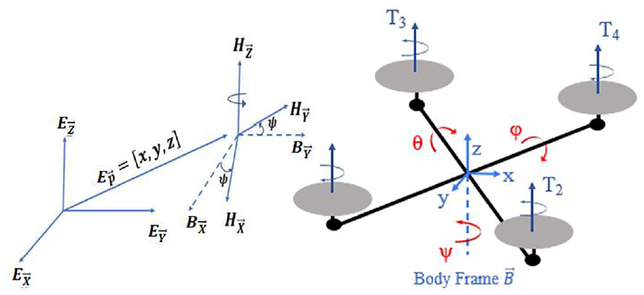
Quadrotor kinematics.
The quadrotor position and rotation vector

where

where V—linear,

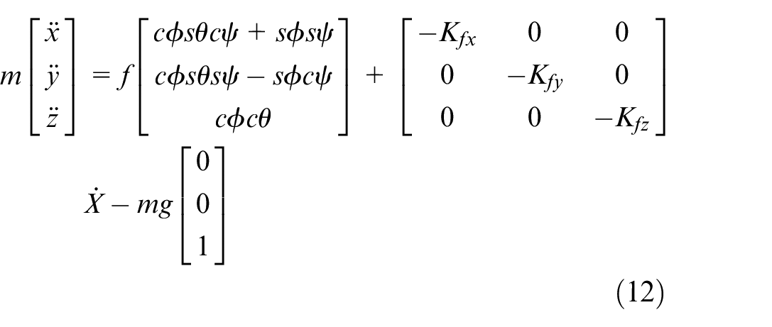
The translational motion connection is calculated using the inertial frame position state variables
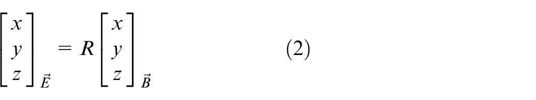
Where R is Rotation matrices:

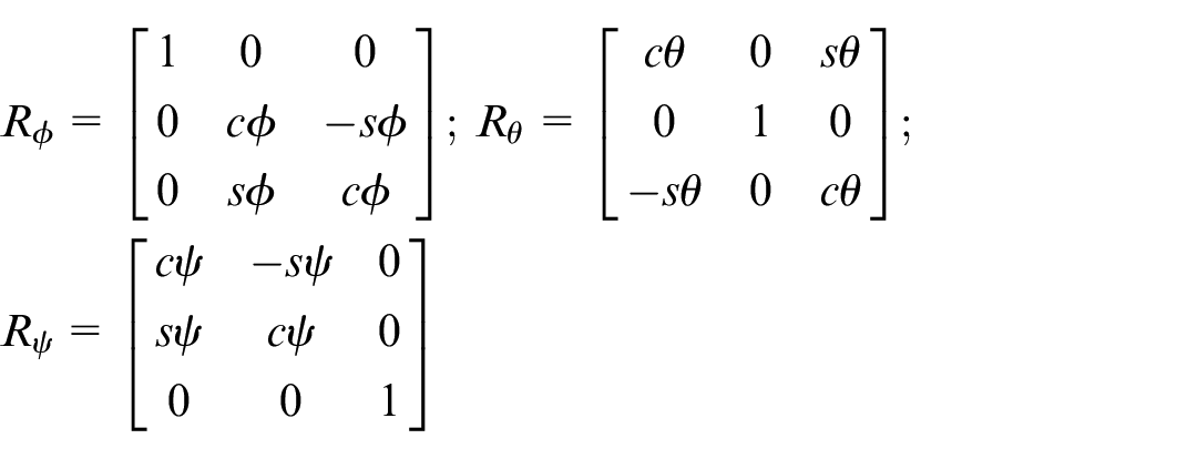
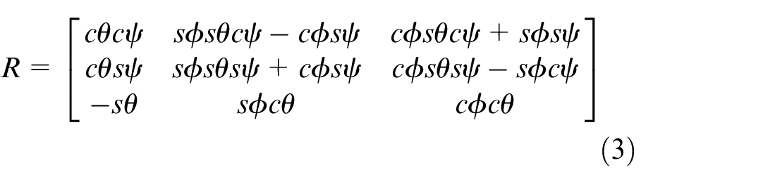
Equations (1) and (3) are defined with sρ = sin(ρ), cρ = cos(ρ) where ρ =
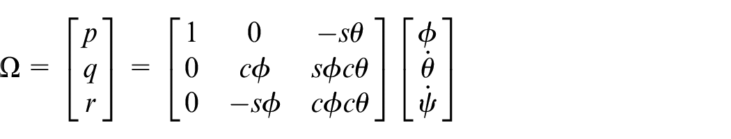
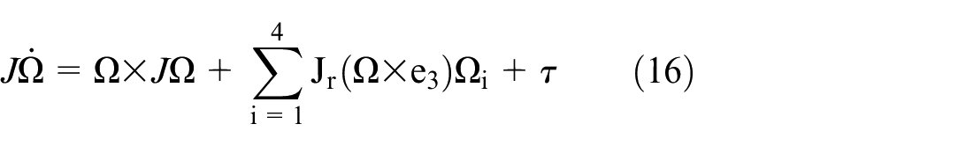
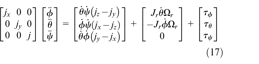
The relation between

And
Assuming that the quadrotor is nearing the stable state, we may rewrite the angular velocity in the inertial frame as:


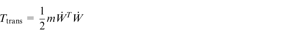
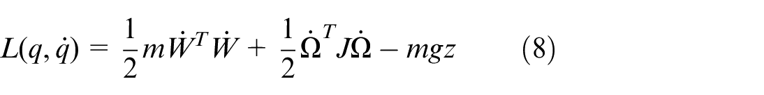
The quadrotor’s translational and rotational kinetic energy is provided by:
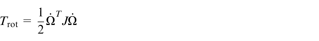
and

Holonomic System:
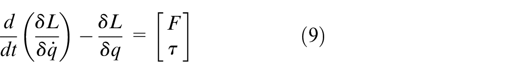
where


Whereas


Where,

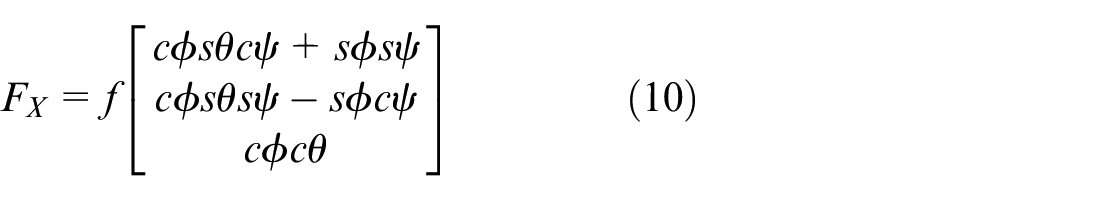
The thrust generated by i-th propeller along b3 is:

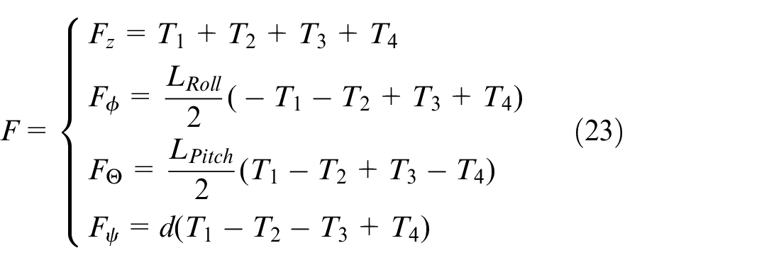
where
The final equation of the relation between u and F:
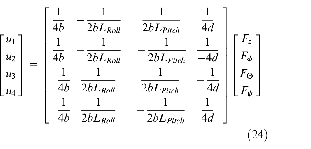
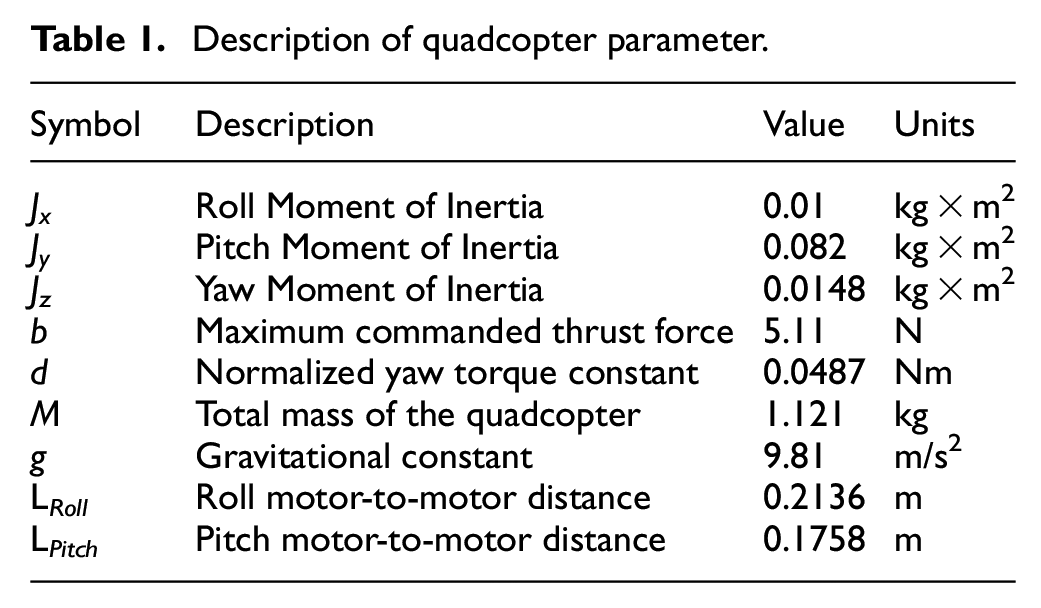
The constants and distances are provided by the manufacturer of the quadrotor used in this research (see Table 1).
Description of quadcopter parameter.
System description
Hardware
The experiments are conducted in a 5.5 × 3.5 m 2 that is enclosed by a safety net (Figure 2(a)). As illustrated in Figure 2(b), six cameras are installed at the corners and edges of the workspace, which are connected by cables to a computer. OptiTrack uses those cameras to determine the UAV’s location and orientation. By attaching special markers to the vehicle, the cameras were able to track the object’s position and orientation as a rigid body. According to the manufacturer’s specified scheme, five markers were attached to the Qdrone as depicted in Figure 3.
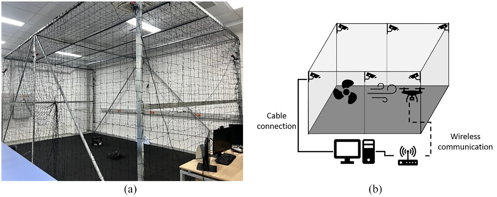
(a) Enclosed workspace with a safety net and rubber flooring and (b) communication scheme.
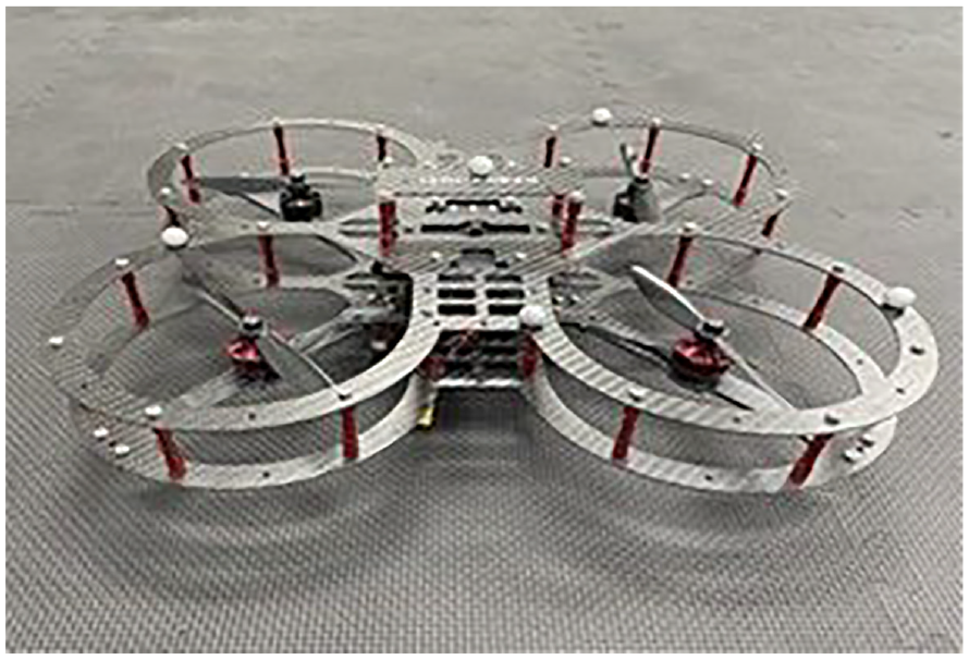
QUANSER’s Qdrone.
During the tests, it was observed that the drone’s behavior became significantly unstable when the battery charge fell below 70% therefore for the better performance the test is conducted under full charge battery.
MATLAB simulink
A Wi-Fi connection and router facilitate communication between Qdrone’s onboard CPU and ground station (computer). The control algorithm and mission server are written in MATLAB Simulink. Table 1 provides the technical specifications of Qdrone. When compared to other practical quadrotors, the main difference in modeling Qdrone dynamics is that L Roll and L Pitch are not the same length, which slightly complicates the final mapping matrix (refer to (1)).
Introducing disturbances to the system
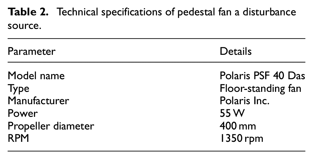
The disturbance is created by a simple pedestal fan manufactured by Polaris Inc. The used fan has a propeller diameter of 400 mm, and a rotation speed of 1350 rpm when the maximum speed mode is turned on. The specifications of the fan are provided in Table 2. In all experiments with disturbance, the fan was placed 1 m away from the Qdrone takeoff point, which is the center of the XY-coordinate system (0, 0). For the case when the disturbance is applied at a 0° angle, the fan was located at (−1, 0) and (0, −1) on XY axes toward positive X and positive Y directions. When the disturbance is applied at a 45° angle, the fan is located at the coordinates (−0.71, −0.71).
Technical specifications of pedestal fan a disturbance source.
Experimental procedure
Figure 4 shows the operation procedure. When the “Mission Server” and “Qdrone Stabilizer” model a start-up, the OptiTrack begins reading the position of the quadcopter and sends it to the “Mission Server.” Depending on whether the position control algorithm is activated, the “Mission Server” calculates the desired position and sends it along with the current position to the “Qdrone Stabilizer.” If the “Take off” button has been triggered, the drone takes off and goes to the desired position. If the position control algorithm is not activated, the drone hovers at a height of 0.8 m from the takeoff point. When the position control algorithm is activated, the “Mission Server” continuously changes the desired position using the time-dependent signal generator block, creating an oscillatory motion. Qdrone continues to receive commands from the “Mission Server” until it receives the “Land” command, at which point it lands and completes the mission.
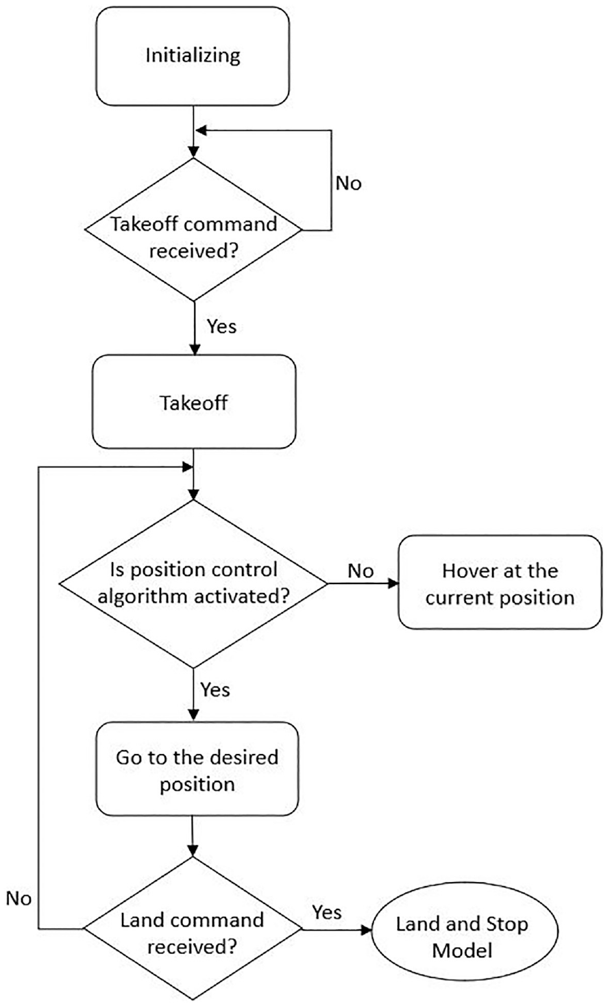
Operation procedure flowchart.
Control strategy and algorithm
Figure 5(a) illustrates the control scheme applied in this study. It involves obtaining the locations (X, Y, Z) and orientations (ϕ, θ, ψ) converting them to a horizon frame (HF), then sending them as input to a controller, and obtaining the thrust (
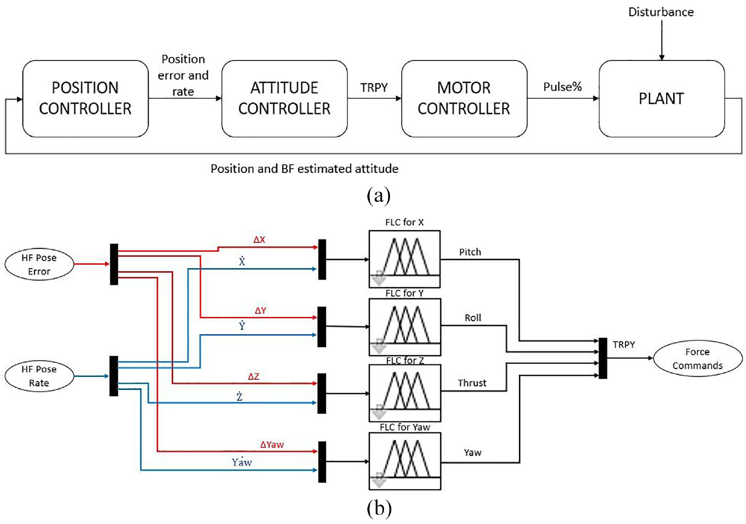
Control scheme of the Qdrone: (a) block diagram and (b) Modi ed Simulink model with FLCs.
PID controller design
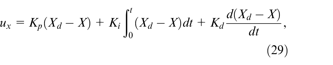
The PID controller was designed by using standard Simulink blocks, including “Gain,”“Integrator,” and “Sum.” The input parameters are position error and velocity error, while the output parameters are controller commands for Thrust (T), Roll (
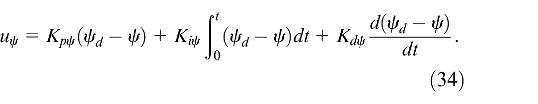
Control laws for yaw (
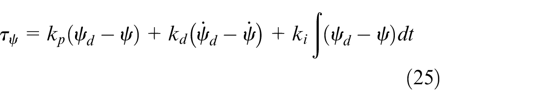
A nested control loop is designed for attitude stabilization to make angle control easier. While the outer loop control attitude angle (


PI controller for the outer loop control attitude angle.
Where
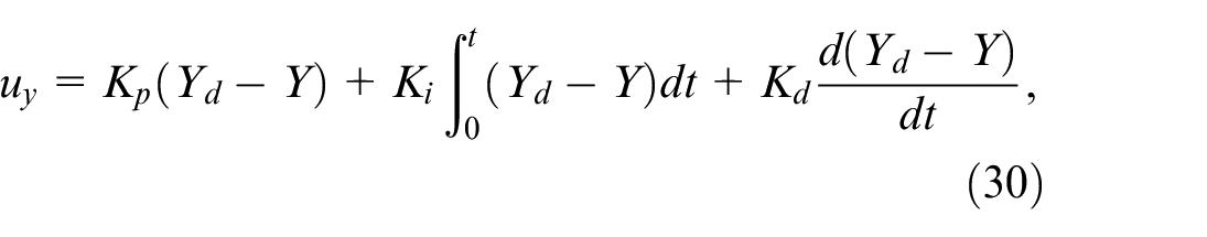
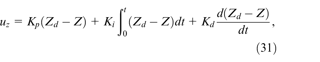
The position controller, that is, outer loop controller is used to give commands for attitude and thus to follow the desired path. Control laws for the outer loop are, 3
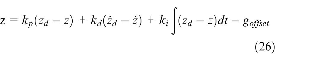
Corrected controller outputs,
Position and altitude from Optitrack system
In Figure, Optitrack cubed space in the inertial frame that monitors the QDrone’s immediate position during each adjustment. This system provides QDrone with accurate position in an interior environment, allowing for a smooth and steady flight path.
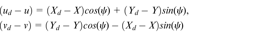
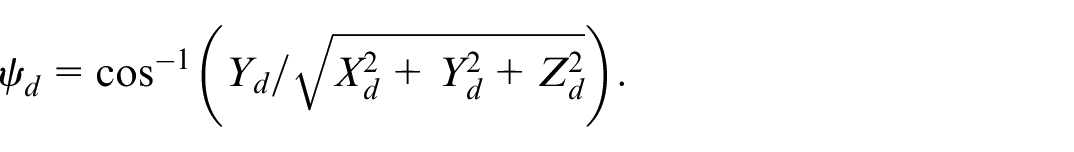
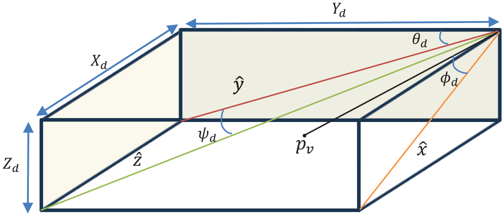
To get the required location, use the desired coordinates X, Y, and Z and the orientation angles
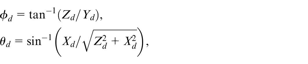
And
POSE inside Opti track system.
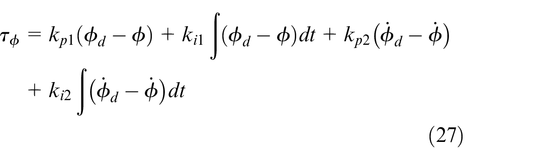
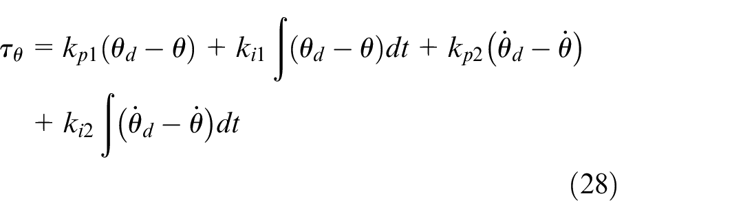
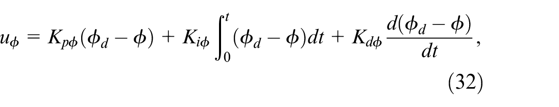
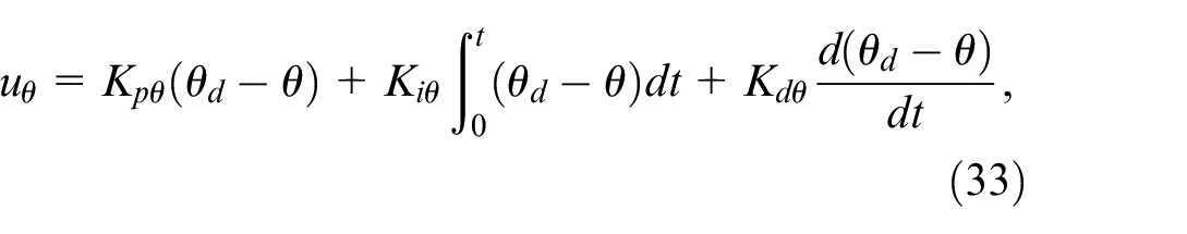
There are six control inputs that must be developed. They are described in Abro et al. 27
And
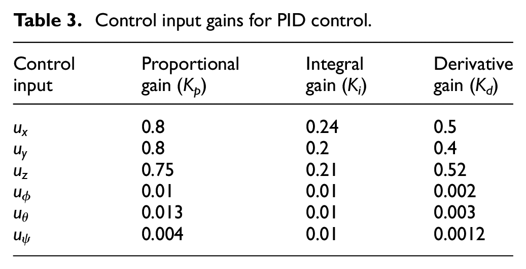
The gains associated with each angle control input vary according to the stability criteria for each motion are provided in Table 3. The position is formulated with (29) to (31) to begin to orient the Qdrone. With (32), (33), and (6) the altitude is achieved by implementing the same gain.
Control input gains for PID control.
Fuzzy logic controller (FLC) design
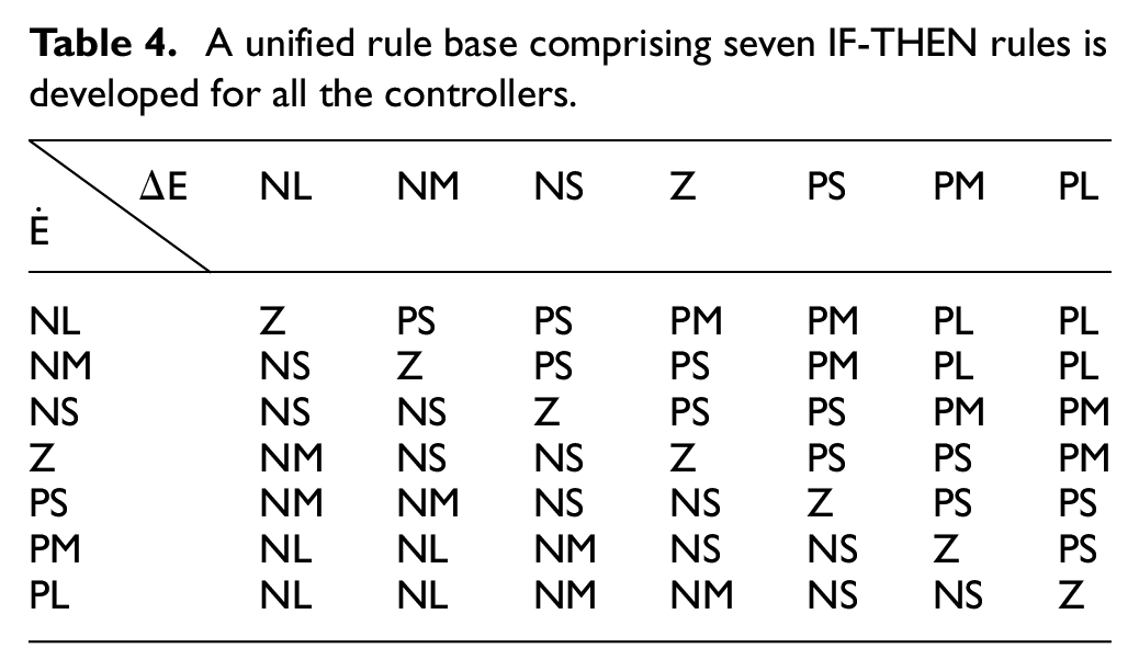
The fuzzy logic controller is designed using the knowledge of the quadrotor’s behavior from its equations of motion, seven membership functions (MFs) for each input and output as shown in Figure 7. The membership functions have triangular and trapezoidal shapes and the centroid method was applied for defuzzification. The rules generated for these functions are provided in Table 4. Here
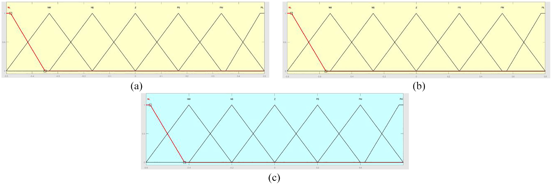
Membership functions design: (a) input variable “position error,” (b) input variable “position rate,” and (c) output variable “TRPY” (input “X” is converted to output “Pitch”).
A unified rule base comprising seven IF-THEN rules is developed for all the controllers.
For the stability analysis of the fuzzy PID controller, the details can be found in Carvajal et al. 31
Prefilter for FLC
In this method, FLC is used to fine-tune the gains of the base controller. However, the process of developing and evaluating the rules and Membership Functions (MFs) traditionally relies relied on specialist knowledge rather than a systematic approach. In this paper, via extensive simulation studies, FLC parameters, including legs of the membership function are selected. Then, they are tested and tuned further using the prefilter approach. The first-order prefilter (PF) is used to adjust the MF parameters depending on the operating condition of the quadcopter UAV to minimize the incurred errors (Figure 8).
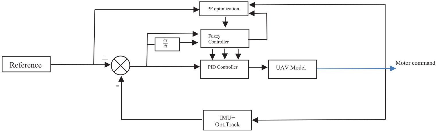
PF-PID control strategy.
Certainly, in control systems, a first-order low-pass filter is commonly represented by the transfer function: G(s)= 1/1+τs where τ in tuning parameter.
Results and discussions: Stability and performance evaluation
Figure 15 shows the experimental results and demonstrates that tests were conducted for three different controller types under three different disturbance scenarios:
No disturbance
Disturbance is produced at a 0° angle to the positive X or Y direction
Disturbance is produced at a 45° angle to the positive X and Y direction
The results present hovering tests, in which the drone was required to maintain its position over the takeoff point. The tests with disturbance applied at a 45° angle were not conducted for Z and Yaw position control, since the fan position can be changed in X and Y directions only. Therefore, the Z and Yaw results with disturbance applied at a 45° angle are identical to those obtained with 0° disturbance.
The most stable behavior for x, y, and yaw position control was achieved using an FLC in the tests without disturbance, with 0° disturbance, and with 45° disturbance, as determined by root mean square error (RMSE) and peak-to-peak (P2P) data analysis. Overall, it was observed that in the majority of cases, the PID controller produced the best results when no disturbance was applied, and the worst when a disturbance was applied at a 0°.
The PF-PID showed the most stable behavior in both experiments conducted for z-position control and exhibited the most accurate reference shape repeat. On the other hand, for the other three components of position control (X, Y, and Yaw), the F-PID controller yielded the most satisfactory results.
The results of the hover test for Yaw shown in Figure 9 demonstrated that the Fuzzy controller was slightly better than the PID controller in maintaining the hover position. However, the PF-PID controller graph depicted an overshoot at the beginning. Similar behavior was also observed for the X position control tests. In fact, the overshoot was observed for all fuzzy + prefilter controllers for Yaw (see Supplemental Appendix A Figure 21).
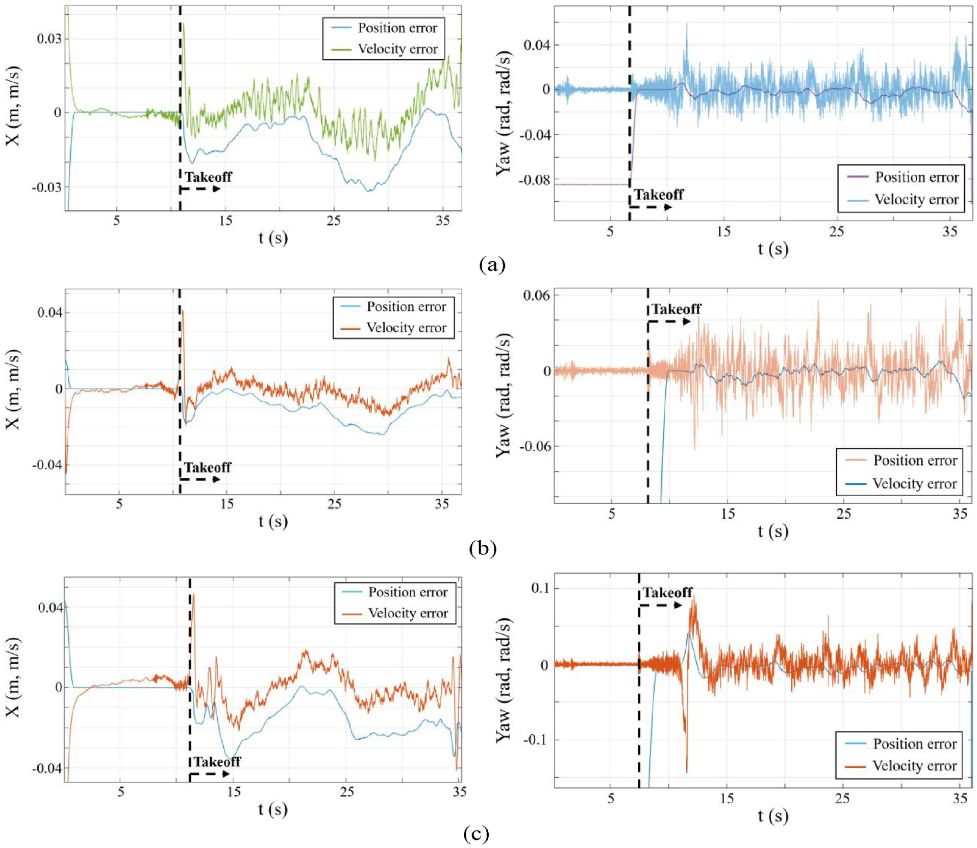
Position error and velocity error (X, Yaw) versus time for hover test with no disturbance applied and disturbance applied at 0° angle: (a) PID, (b) R-PID and (c) PF-PID.
In the hover test for Y position control, as depicted in Figure 10, the PID controller performed worse than the other two controllers. However, the table shows that the RMSE error for the PID controller is less than that for the PF-PID controller. This was due to the fluctuations that appeared in the test with PF-PID. Nevertheless, the peak value was significantly lower, and the F-PID controller demonstrated the best result. When considering the position control test for Y in Figure 9, it is clear that the F-PID and PF-PID controllers graphs are significantly more accurate compared to the PID controller.
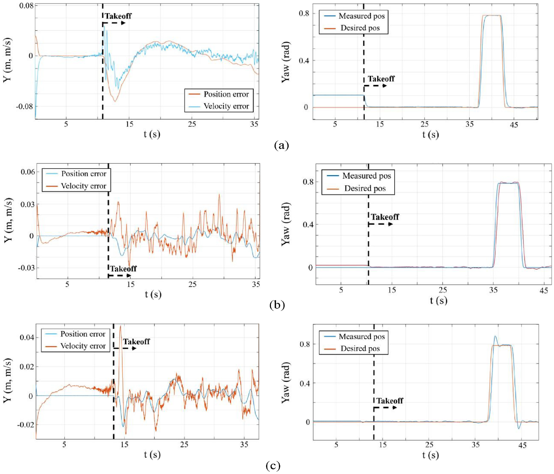
Hover (for Y) and position control (for Yaw) tests results: (a) PID, (b) R-PID and (c) PF-PID.
The results of the Z-position controller tests, as shown in Figure 11, are somewhat uncertain. The PID controller results exhibited some overshoots and undershooting when the position was changed. The F-PID controller behaved more stably in comparison; however, the best reference line shape repeat was achieved by the PF-PID controller, even though it showed the most significant fluctuations. The hover test results in the table show that the PF-PID produced fewer deviations from the desired point in both cases.
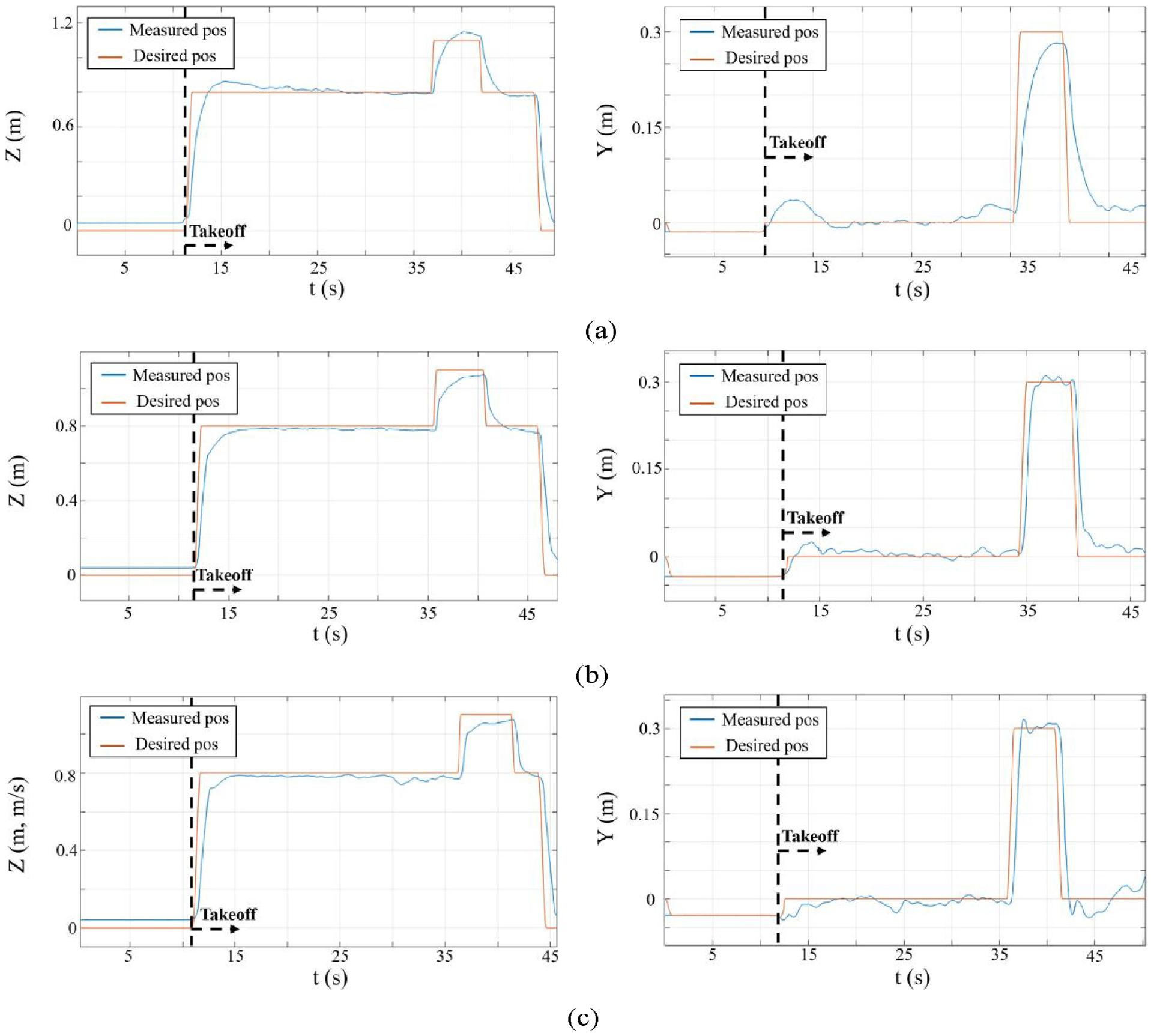
Z, Y versus time graphs for position control test with disturbance applied at 0°and 45° angle: (a) PID, (b) R-PID and (c) PF-PID.
A total of 60 experiments were conducted, with 20 for each of the three types of controllers tested. The results of the hover test for the PID, F-PID, and PF-PID controllers under three different conditions are illustrated in Figures 12 to 14, respectively. The corresponding controller command graphs for these experiments are provided in Figures 15 to 17.
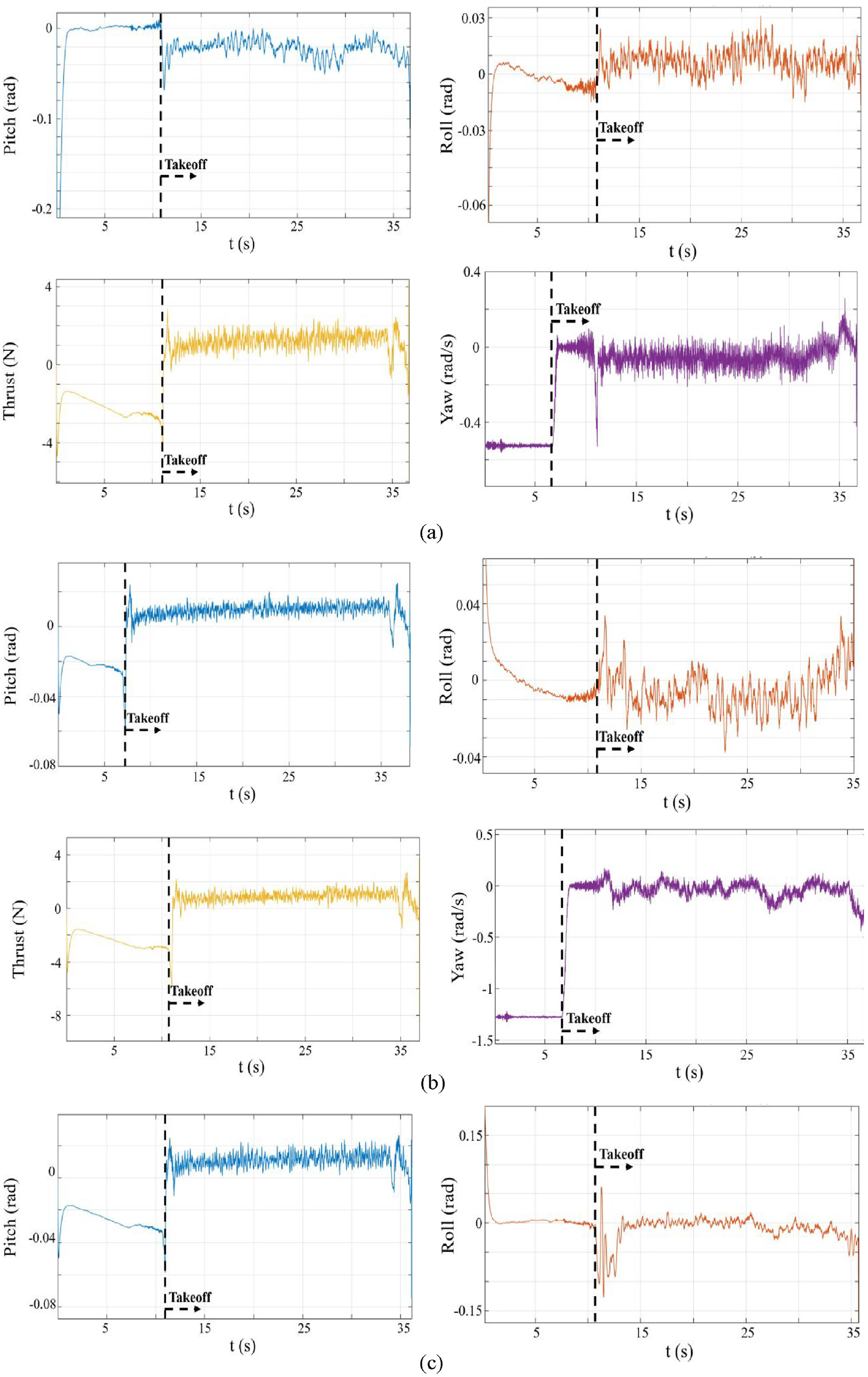
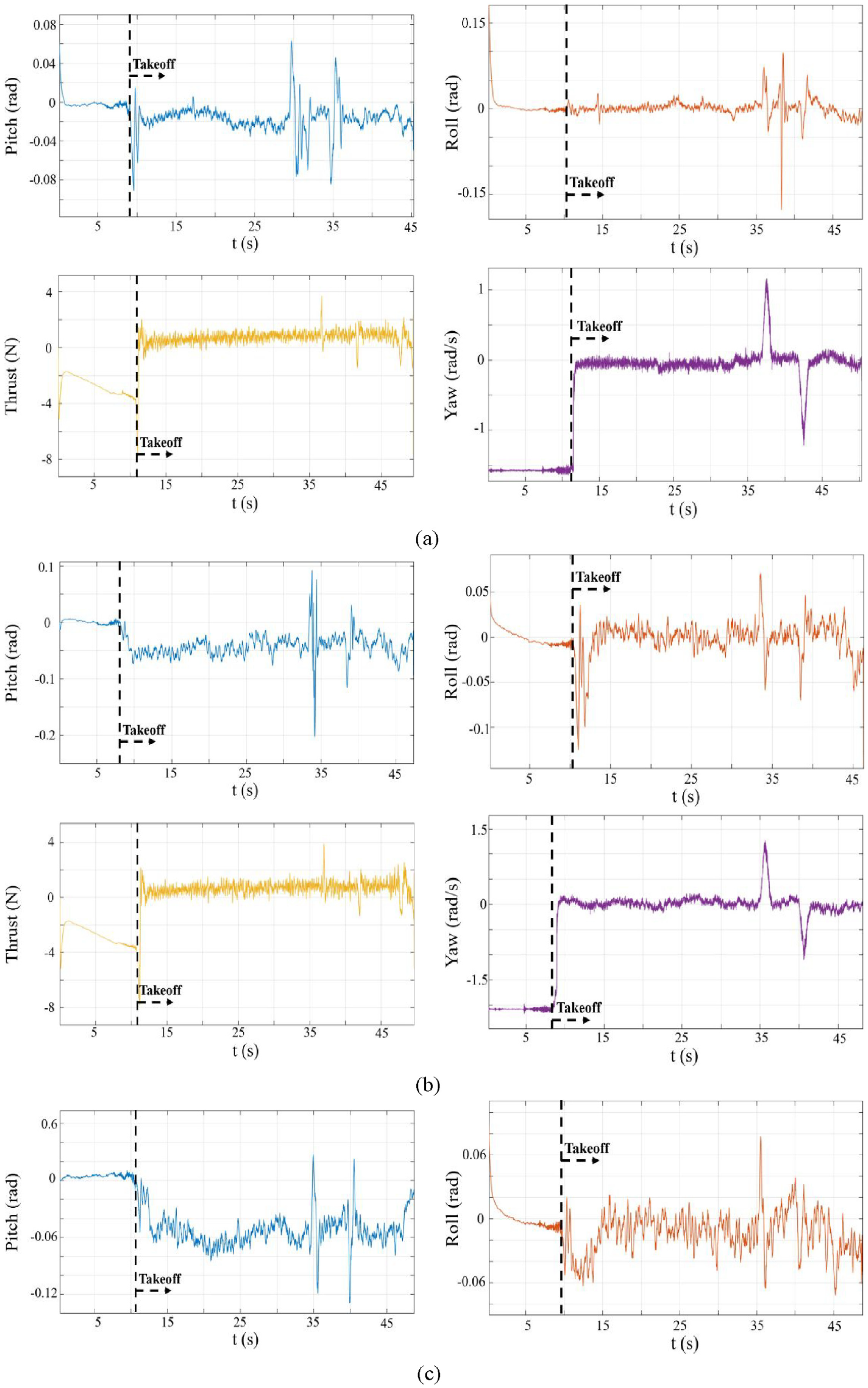
Unsaturated controller commands versus time (Hover test, PID): (a) disturbance is not applied, (b) disturbance applied at 0° angle, and (c) disturbance applied at 45° angle.
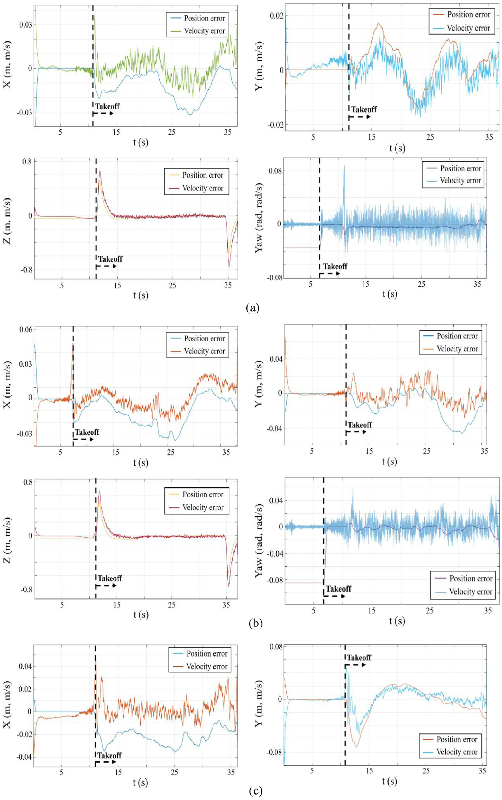
Position error and velocity error versus time (Hover test, PID): (a) disturbance is not applied, (b) disturbance applied at 0° angle, and (c) disturbance applied at 45° angle.
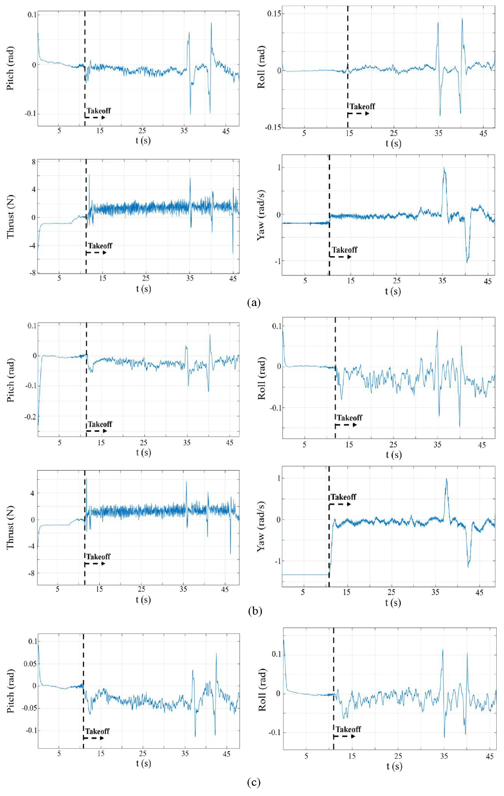
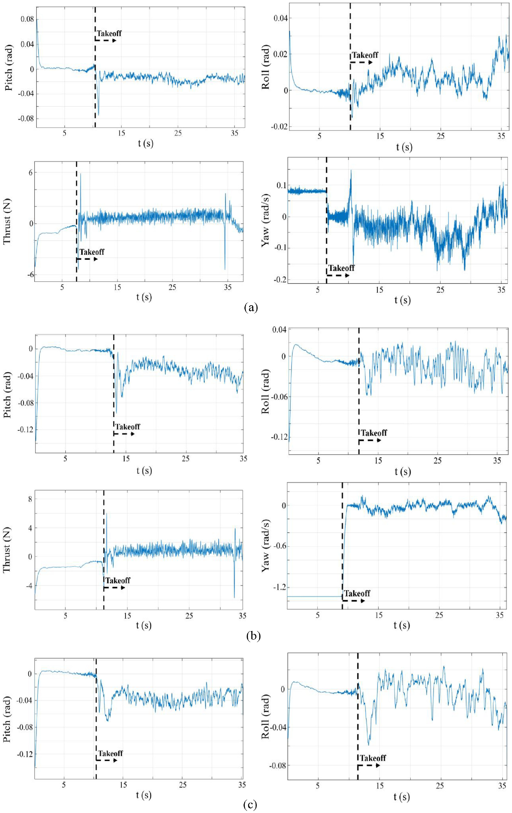
Unsaturated controller commands versus time (Position control test, Fuzzy controller): (a) disturbance is not applied, (b) disturbance applied at 0° angle, and (c) disturbance applied at 45° angle.
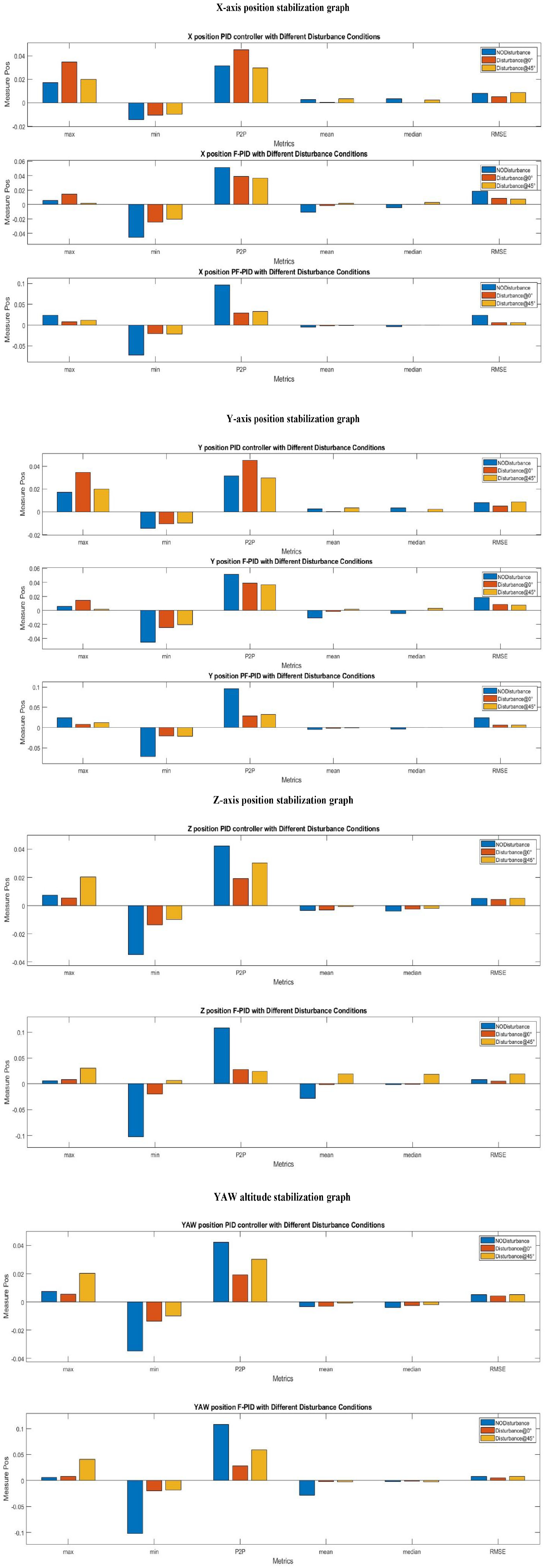
Hover test results for three types of controllers with and without disturbance. X-axis position stabilization graph. Y-axis position stabilization graph. Z-axis position stabilization graph. YAWaltitude stabilization graph.
Unsaturated controller commands versus time (position control test, PID): (a) disturbance is not applied, (b) disturbance applied at 0° angle, and (c) disturbance applied at 45° angle.
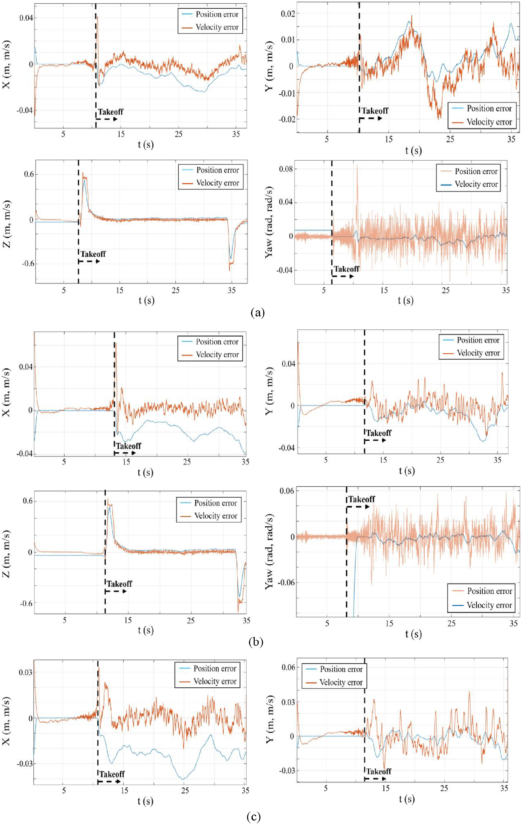
Position error and velocity error versus time (hover test, fuzzy controller): (a) disturbance is not applied, (b) disturbance applied at 0° angle, and (c) disturbance applied at 45° angle.
The position control test results are depicted in Figures 18 to 20, 22, and 24 for the PID, F-PID, and PF-PID controllers, respectively. The corresponding controller command graphs for these experiments can be found in Figures 14, 20, 21, and 23. The hover test findings demonstrated that the PF-PID caused the drone to behave most steadily during tests conducted for Z-position control. At that time, the F-PID was the leader in tests of controlling the other 3 components of position (X, Y, Yaw). While in position control tests the results conducted for yaw show that the PID controller performs slightly better than the Fuzzy controller, while PF-PID demonstrated the worst behavior, which was caused by overshoots. This means that the prefilter may be tuned better in further works. The X, Y, and Z position control test results show that PID controller performance is less accurate compared with the other two controllers.
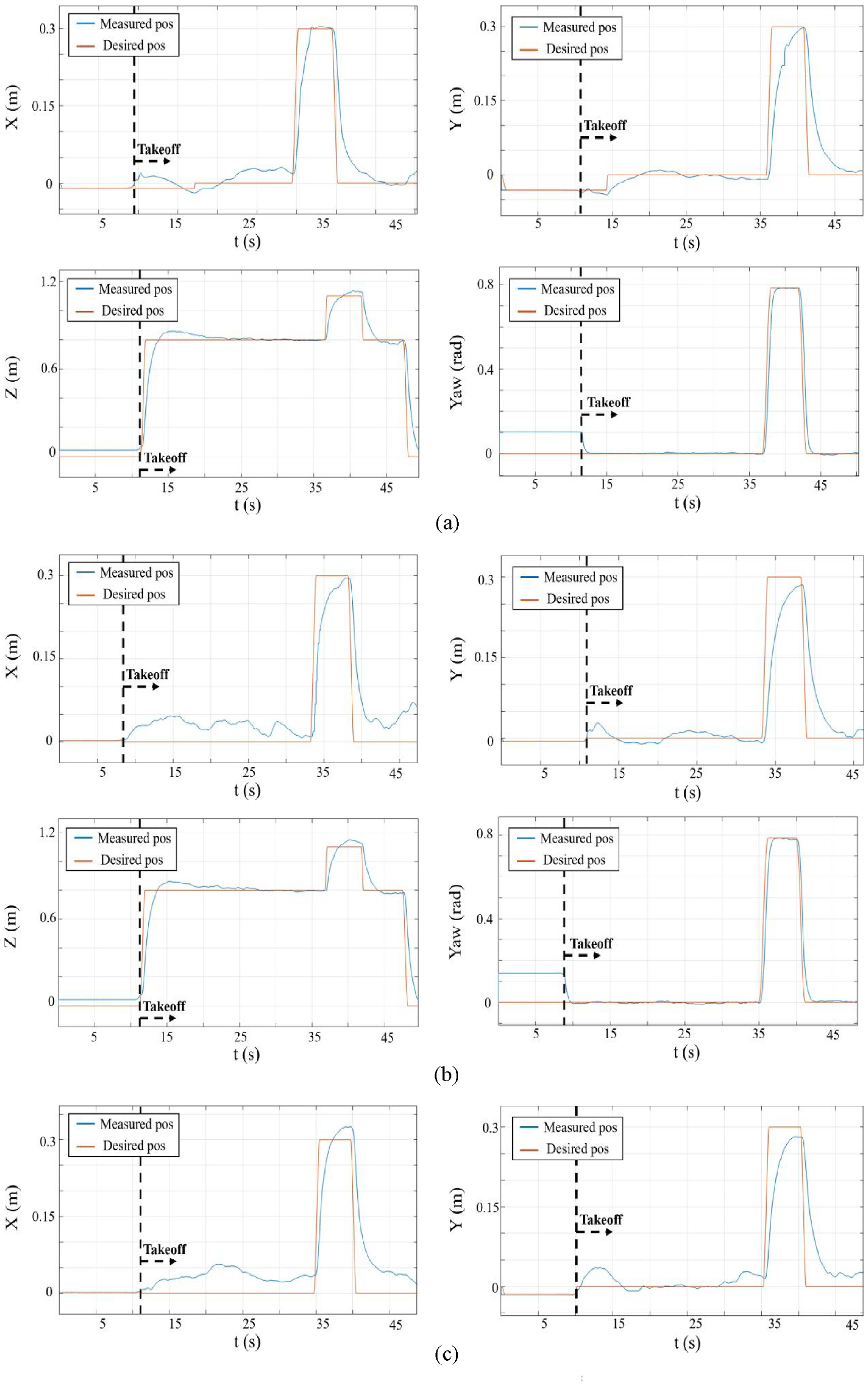
Position versus time (position control test, PID): (a) disturbance is not applied, (b) disturbance applied at 0° angle, and (c) disturbance applied at 45° angle.
Unsaturated controller commands versus time (hover test, fuzzy controller): (a) disturbance is not applied, (b) disturbance applied at 0° angle, and (c) disturbance applied at 45° angle.
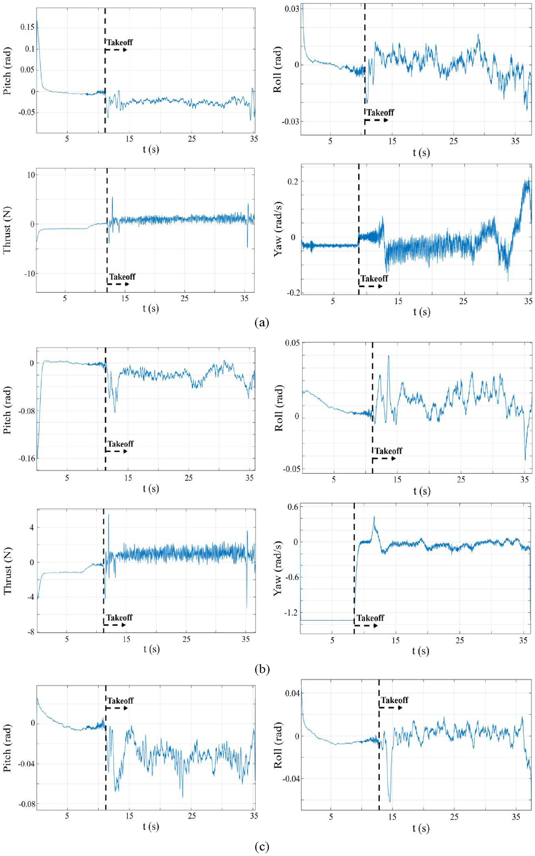
Unsaturated controller commands versus time (hover test, fuzzy controller with prefilter), (a) disturbance is not applied, (b) disturbance applied at 0° angle, and (c) disturbance applied at 45° angle.
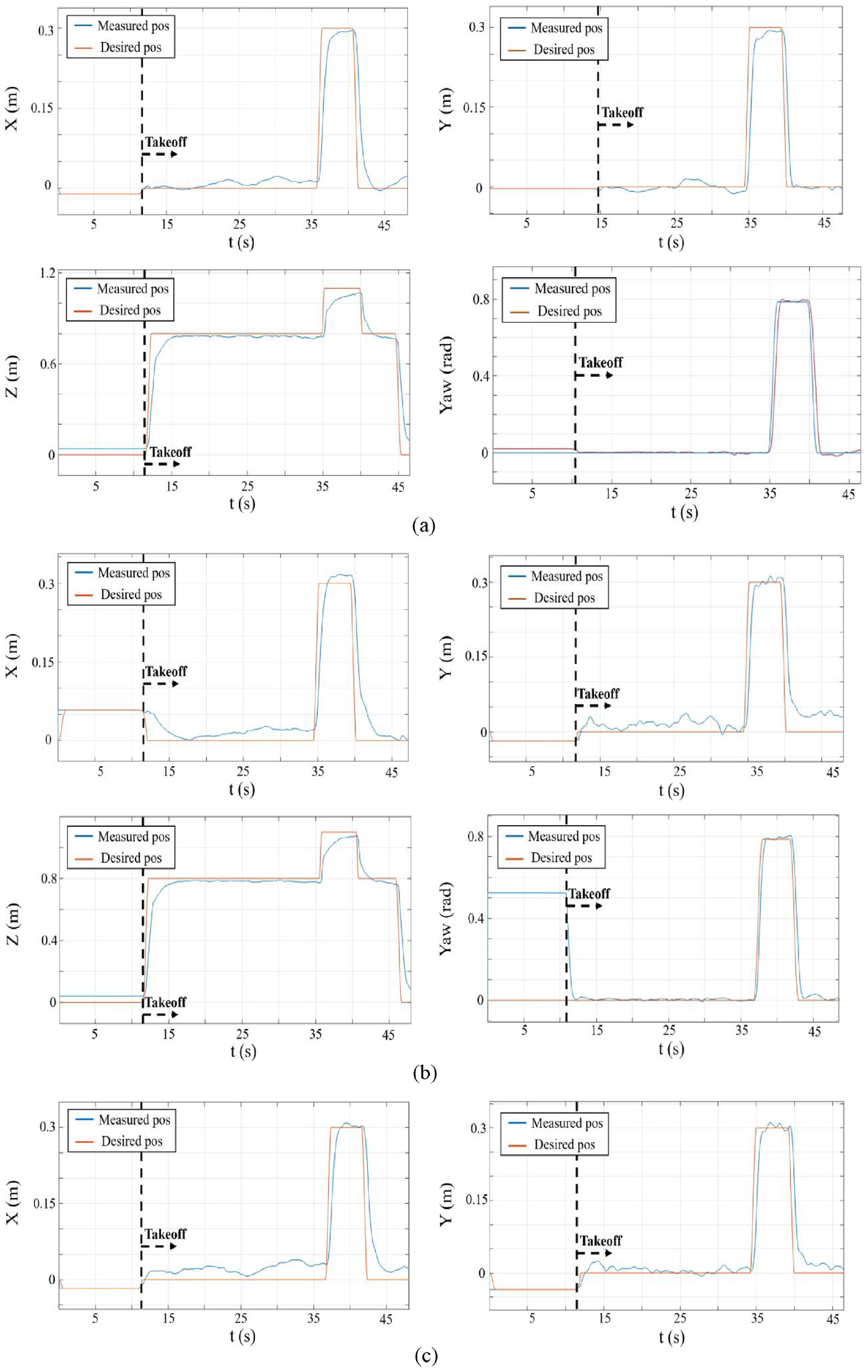
Position versus time (position control test, fuzzy controller): (a) disturbance is not applied, (b) disturbance applied at 0° angle, and (c) disturbance applied at 45° angle.
Conclusion
In conclusion, this research presents the development of an optimal controller for a drone with a camera-based reference point. The experimental results show that the designed Fuzzy controller is more accurate and effective in controlling the position of the drone than the PID controller. Furthermore, the integration of the optimal Fuzzy controller into the drone with a Fuzzy controller has shown to be effective in avoiding obstacles and maintaining the desired position of the drone. The proposed algorithm and controller contribute to the advancement of the field of robotics and autonomous systems and can be applied in various industries such as transportation, surveillance, and agriculture. The system’s behavior was compared in this article. For this, a controller was designed using a drone and tested with and without disturbance such as external air blow with a fan. It was observed during the tests that the drone’s behavior became noticeably unstable when the battery charge fell below 70%. For this reason, all tests were carried out with full battery charge and at an equal distance from the take-off point to the pedestal fan. The hover test findings demonstrated that the prefiltered FLC caused the drone to behave most steadily during tests conducted for Z-position control. At this position, the FLC without a prefilter was the leader in tests of controlling the other three components of position (X, Y, Yaw). While in position control tests, the results conducted for yaw show that the PID controller performs slightly better than the Fuzzy controller, while FLC with prefilter demonstrated the worst behavior, which was caused by overshoots. This means that the prefilter may be tuned better in further works. The X, Y, and Z position control test results show that PID controller performance is less accurate compared with the two other controllers. The optimal fuzzy controller with 49 rules showed the most accurate results in all tests and can be implemented in various leader-follower systems.
Finally, regarding future works, by incorporating the disturbance observer into the control system, the active disturbance rejection control will be considered in the future to handle the cases of disturbances (for example, the wind) better. Also, robust controllers such as sliding mode control, and adaptive control can be implemented and analyzed in the near future.
Graphical results for the experiments
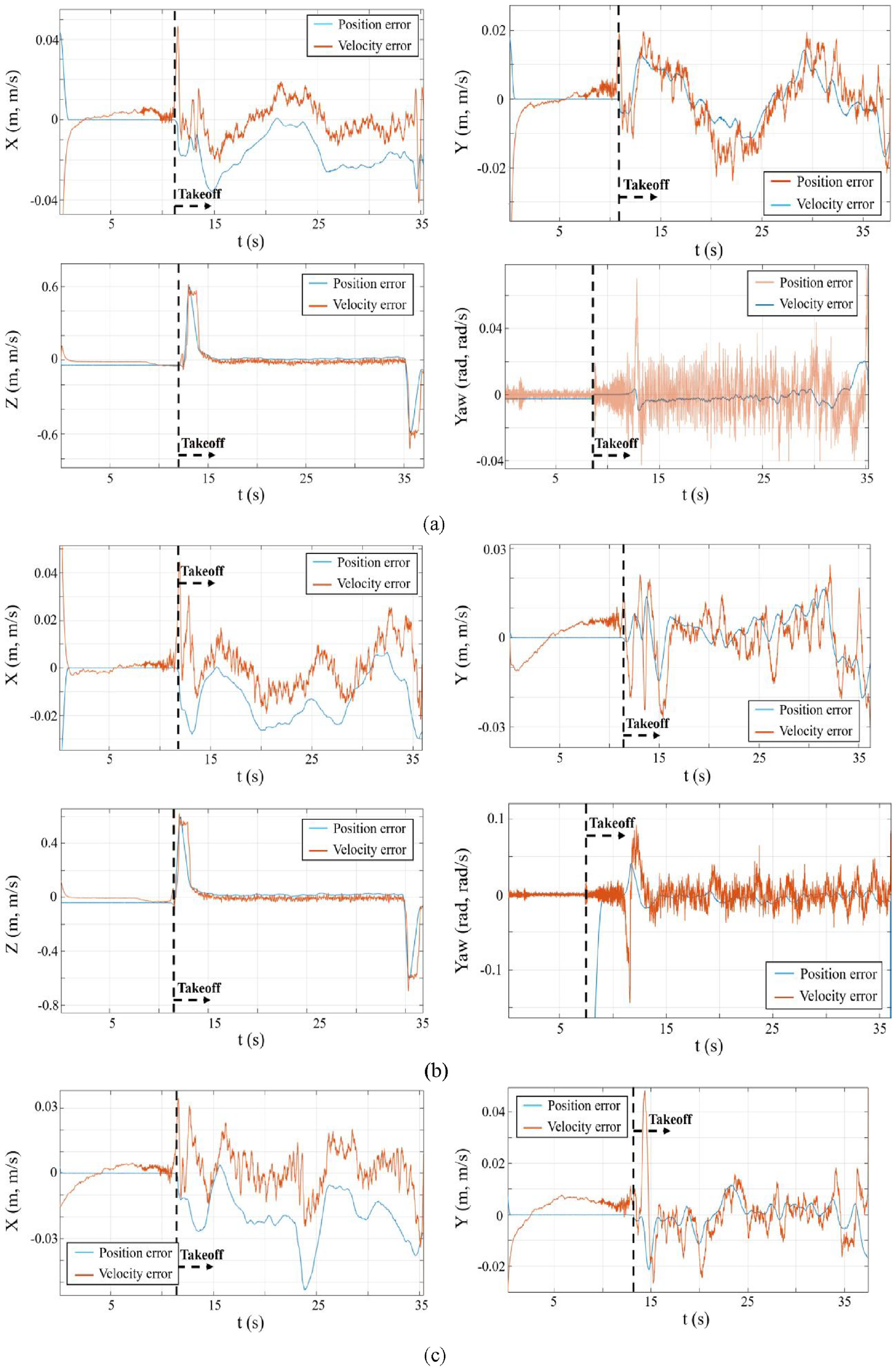
Position error and velocity error versus time (hover test, fuzzy controller with prefilter): (a) disturbance is not applied, (b) disturbance applied at 0° angle, and (c) disturbance applied at 45° angle.
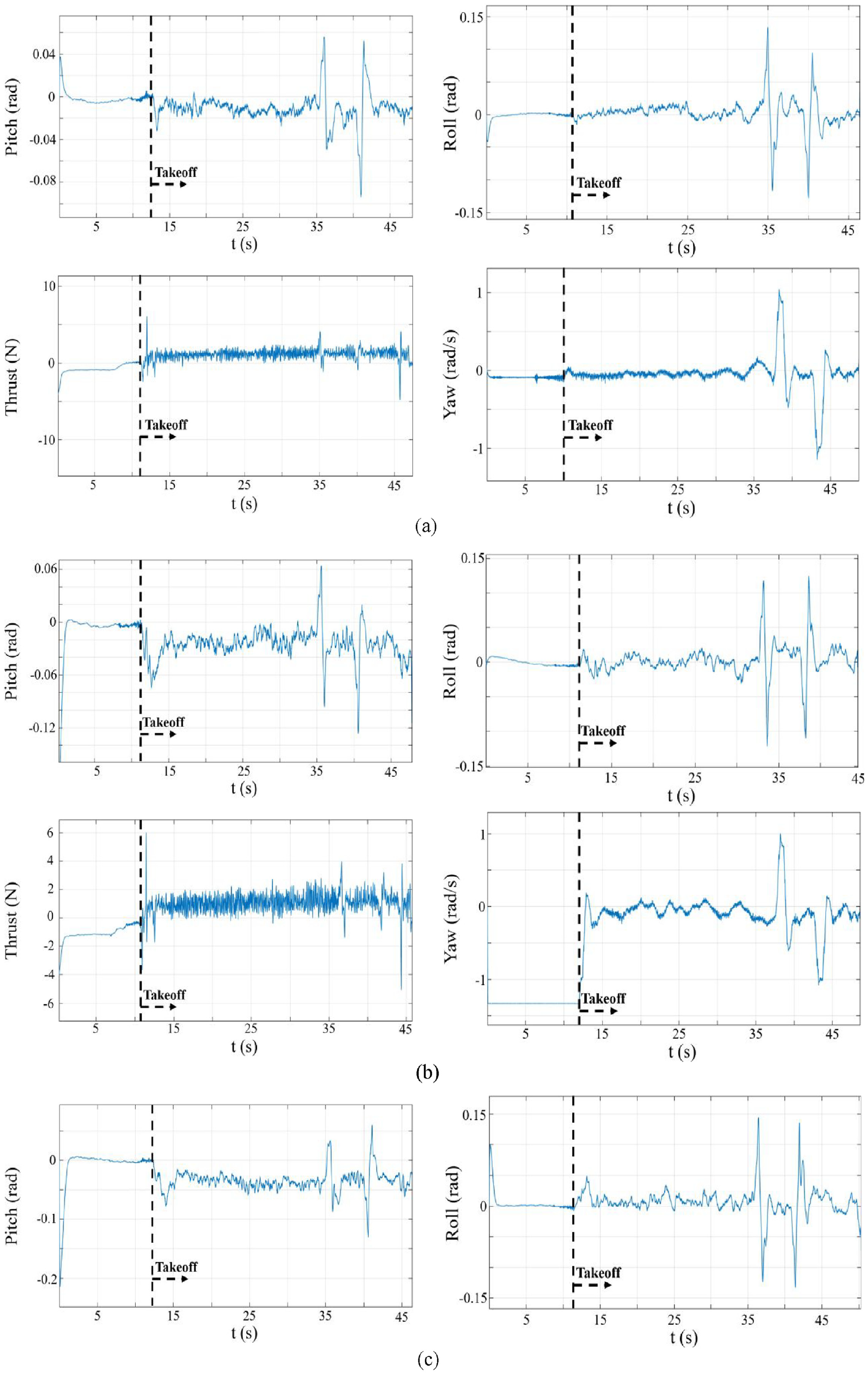
Unsaturated controller commands versus time (position control test, fuzzy controller with prefilter): (a) disturbance is not applied, (b) disturbance applied at 0° angle, and (c) disturbance applied at 45° angle.
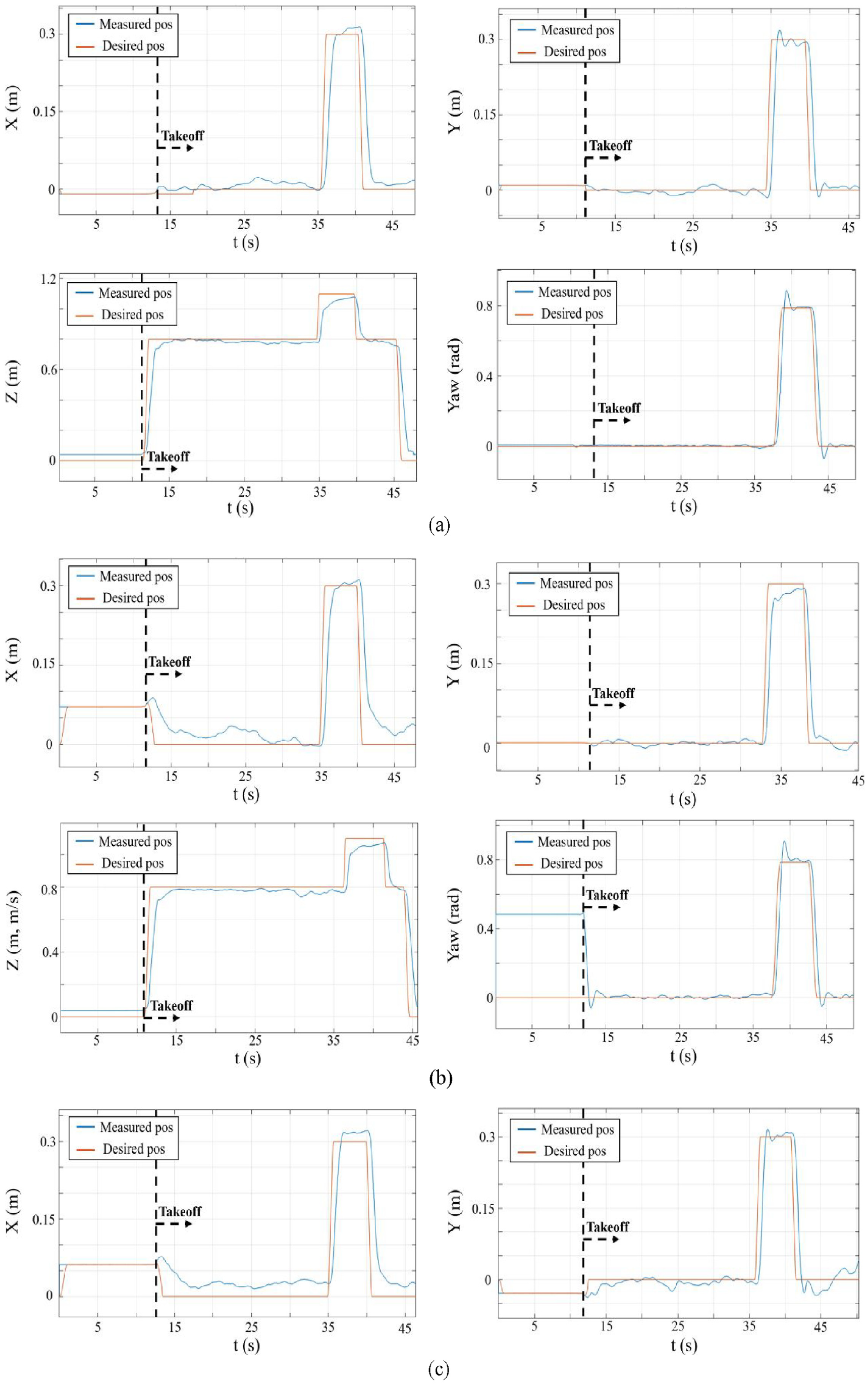
Position versus time (position control test, fuzzy controller with prefilter): (a) disturbance is not applied, (b) disturbance applied at 0° angle, and (c) disturbance applied at 45° angle.
Footnotes
Declaration of conflicting interests
The author(s) declared no potential conflicts of interest with respect to the research, authorship, and/or publication of this article.
Funding
The author(s) disclosed receipt of the following financial support for the research, authorship, and/or publication of this article: This research is supported by Nazarbayev University under Collaborative Research Program Grant No 11022021CRP1509.
Data availability statement
Data sharing not applicable to this article as no datasets were generated or analyzed during the current study.