
Abstract
The belt conveyor is susceptible to longitudinal tearing, which poses a serious threat to the safety of coal mines. Traditional methods for detecting longitudinal tears have limitations such as poor image quality, limited applicability, and high hardware costs. An improved encoder-decoder network was proposed to solve the longitudinal tear detection problem. This method utilizes a line structured light system for image acquisition. The input images are downscaled using a sorting algorithm to extract the information of pixels with high grayscale values as the input feature map for the neural network. The reduced-dimensional encoder-decoder network then semantically segments the input feature map, and the resulting pixel segmentation is mapped to the location of the longitudinal tear. Finally, the position and length of the tear are calculated by back-projecting the semantic segmentation result to the world coordinate system. Experimental results demonstrate that this method effectively reduces hardware resource consumption and improves detection speed. The DICE and MIOU scores for the improved network are 97.69% and 95.47%, respectively, while the recall and precision for improved detection are 96.60% and 95.67%, respectively. Therefore, this method can successfully monitor longitudinal tear failures and ensure the safety of transportation.
Introduction
Coal transportation is a crucial step in the production of coal mines. The belt conveyor is a vital piece of equipment used for coal transportation, widely utilized in non-coal mines, docks, and other industries. It offers numerous advantages, including strong capacity, low cost, and reliability. However, one of the most common failures of belt conveyors is longitudinal tearing. 1 This can be caused by various factors, 2 such as hard foreign objects getting trapped in the coal stream and pressing, smashing, or scratching the belt during transportation. Additionally, design defects or incorrect installation of the conveyor can lead to damage from other sharp equipment. Belt deflection can also cause the rollers or steel frame to scratch the belt. Even a small longitudinal tear in the belt can result in the accumulation of floating coal. If not addressed promptly, this can lead to the belt breaking and the coal being dumped. In the worst case scenario, the belt conveyor can be damaged, and the operator’s safety can be compromised. Therefore, early detection of longitudinal tears in the belt is crucial for both economic and social benefits.
Currently, there are three main categories of methods for detecting longitudinal tears in belts 3 : sensor detection,4,5 multispectral detection, 6 and image detection. 7 With the rapid advancement of artificial intelligence and computer hardware, image-based detection methods have become increasingly popular due to their higher speed and accuracy, as well as their lower installation and maintenance requirements. As a result, computer vision has been widely adopted to address the issue of belt tear detection, 8 making it a key area of research in the field of coal mine intelligence. Within computer vision, there are two main approaches: machine vision 9 and deep learning. 10
The foundation of machine vision lies in feature extraction and identification, a task that demands the expertise of experienced researchers in its design. Yang et al. 11 designed a conveyor belt tear detection method based on infrared spectral analysis. The infrared radiation field of the longitudinal tear is detected by infrared thermography, then after Fourier transform, the frequency domain characteristic coefficients are used to determine whether the longitudinal tear of the conveyor belt has occurred. Li and Miao 12 used the improved SSR algorithm to extract the features of the longitudinal tear image, the features include area, fineness and rectangularity, etc., and then determines the longitudinal tear status. Hou et al. 13 proposed a longitudinal tear detection algorithm based on audio and video, which is used to collect image and sound signals from the conveyor belt using a camera and microphone array, respectively. Images and sounds are analyzed, and the results are combined to determine the status of the conveyor belt. Wang et al. 14 proposed a cascade classifier in order to solve the problem that the light of the belt conveyor varies drastically and unevenly. Haar features are used to train the weak classifier, and the AdaBoost algorithm is used to upgrade the weak classifier to a strong classifier, and then this method can reduce the training and processing time. These methods focus on either extracting or recognizing features.
The foundation of deep learning lies in the hierarchical structure of neural networks. Zhang et al. 15 proposed a belt longitudinal tear detection algorithm based on object detection. This algorithm is based on yolov3 and replaces Darknet53 with EfficientNet as the backbone network. The experiments show that this method can effectively ensure the safe and stable operation of the conveyor system. Guo et al. 16 studied the MCC-CycleGAN method in order to solve the longitudinal tear detection. This is an adversarial generative network designed with a generator and a discriminator to generate longitudinal tear images and detect images, respectively. Qu et al. 17 proposed an adaptive deep convolutional network method for longitudinal tear detection. Different scale features of image are extracted by adaptive depth convolution, and then the target is classified and localized in the form of an anchor box. Their research focuses on improving existing neural network structures for longitudinal tear detection.
Although the above methods are effective for longitudinal tear detection, some problems exist as follows: (1) poor lighting conditions in coal mines, the quality of the images is poor, leading to a decrease in accuracy; (2) the image features are designed by the researcher, and when the coal mine conditions change, the old tear features are no longer applicable and need to be redesigned, so the generalization ability is poor; (3) Many methods only have longitudinal tear detection, but lack length measurement; (4) Some detection equipment is expensive or causes occupational injuries, such as X-rays.
To address these issues, we propose a belt tear detection algorithm that utilizes encoder-decoder networks. The image acquisition device used is a line structured light, which not only serves as a lighting equipment, but also emits a laser with structural information for accurate length measurement. This type of light is safe for human use and more cost-effective compared to other devices such as spectral cameras and X-rays. The improved network follows a standard data-driven approach, eliminating the need for experienced researchers in sample collection and labeling. This makes it easier to adapt to various application environments, ultimately improving its generalizability.
Longitudinal tear detection system
Hardware design
The belt conveyor tear detection system consists of a line laser, an industrial camera, and an edge computing device. The line laser and industrial camera work together to create a line structured light system. The industrial camera captures the line laser’s reflection on the belt, and the resulting images are analyzed to detect any longitudinal tears. The edge computing device is equipped with computation and control capabilities, and its GPU is responsible for performing neural network inference.
The hardware design of the detection system is shown in Figure 1. The detection system is installed between the upper and lower belts at a distance of about 0.5 m from the upper belt, as far as possible in the middle of the two rollers, so that longitudinal tear feature is highlighted when the belt is tensioned.
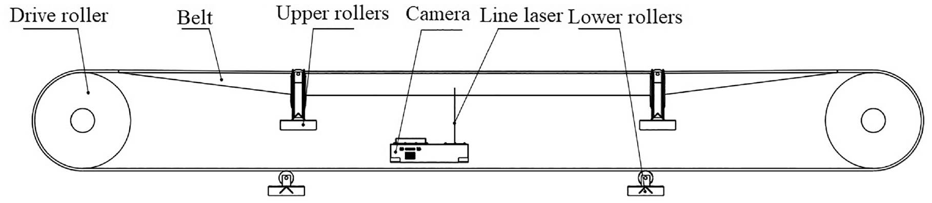
The hardware design of the detection system.
Framework of the detection
The proposed method is divided into four steps: image acquisition, image preprocessing, neural network inference, and image postprocessing. As can be seen from Figure 2, image acquisition is a line structured light system. Image preprocessing, neural networks and image postprocessing constitute the entire detection algorithm. The main innovation is the improvement of the encoder-decoder networks, which makes the model smaller and faster.

Flowchart of the algorithm.
The detailed improvements of the proposed method
Image acquisition
Line structured light 18 is the image acquisition device for the detection. As can be seen from Figure 3, there are three coordinate systems: x-y-z is the world coordinate system, x c -y c -z c is the camera coordinate system, and j-i is the image coordinate system. Suppose the laser curve equation is Iobject(x,y,z) and in the image the equation is Iimage(j, i).
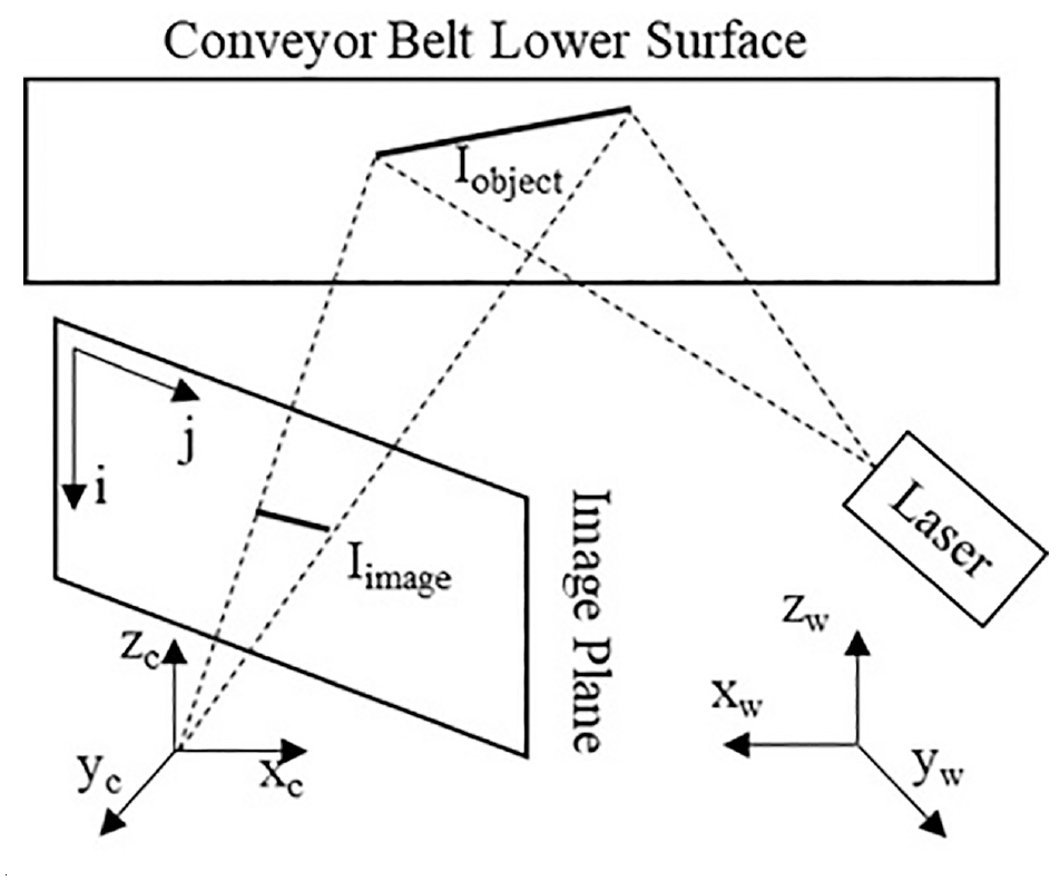
Line structured light model.
Two important geometric models 19 are described as follows:
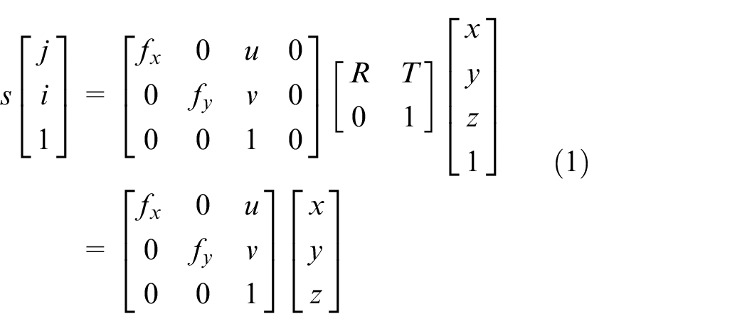
Where s is the normalization factor,

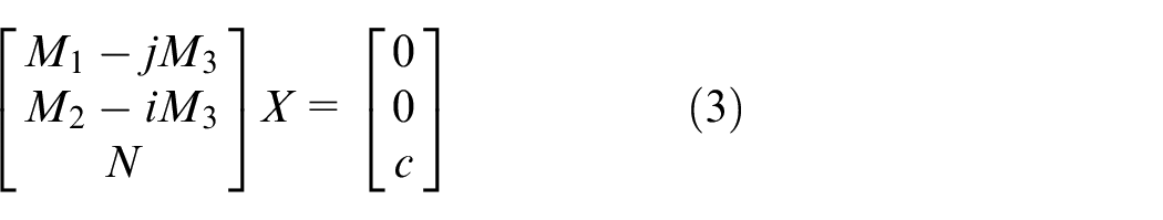
Where N is the normal of the laser plane and c is constant.
These parameters such as
Where
Image preprocessing
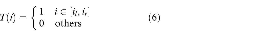
The original image captured by the line structured light is shown in Figure 4. However, these images are two-dimensional data, and most of the image area is black pixels, so there is redundancy in the image data. Image pre-processing algorithms are proposed for reducing information redundancy. Image pre-processing has two components: Optimization of input feature maps and annotation.
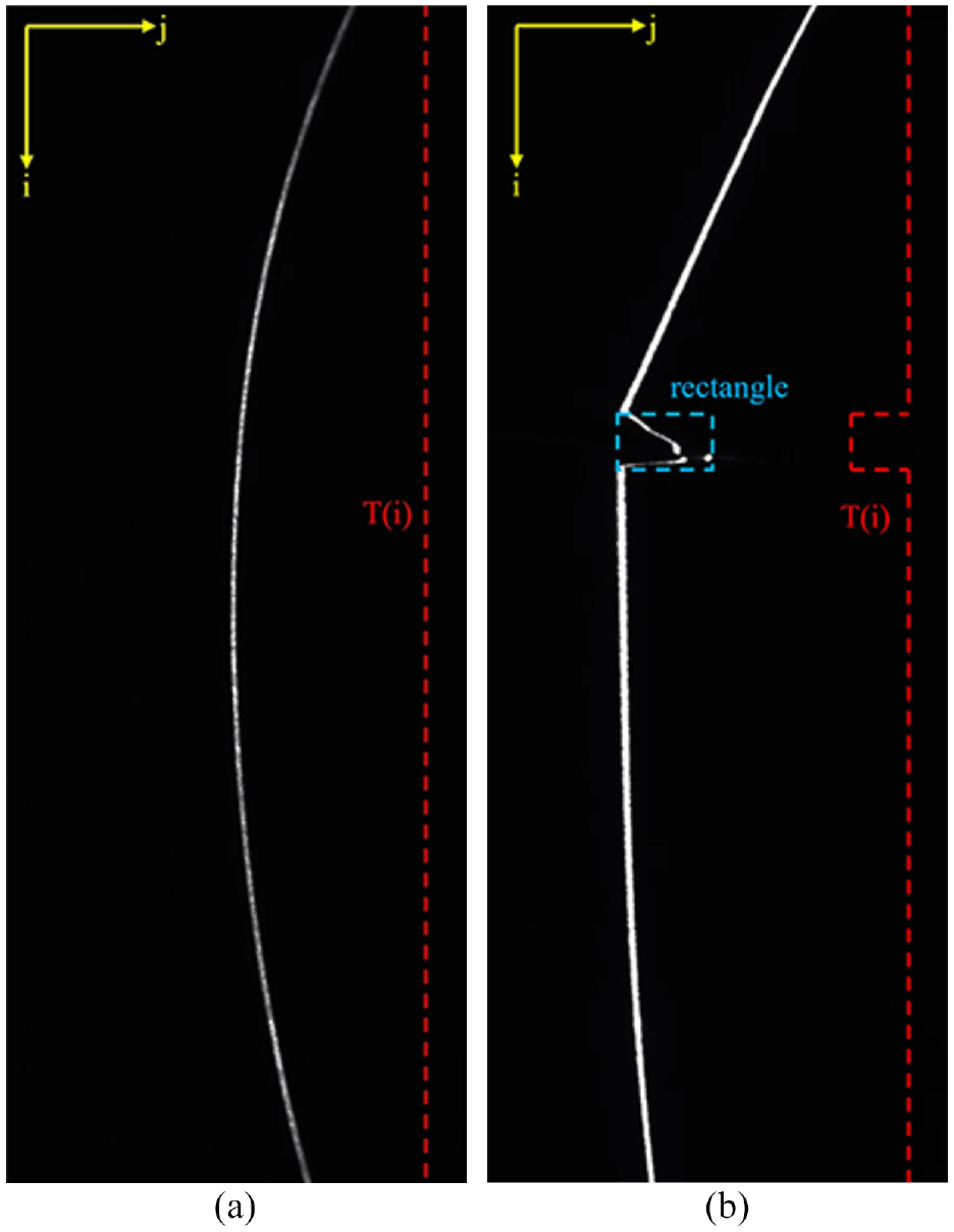
Image acquisition and annotation: (a) normal belt and (b) belt with longitudinal tear.
The purpose of the optimization of the input feature map is to make the size of the feature map smaller. The laser stripes are the most important information, which are white pixels in image. The Topk method is proposed to extract white pixels efficiently. To be precise, the Topk is to return the k largest elements of the given input tensor along j-axis. Suppose I(i, j) denotes the grayscale image which size is


In traditional convolutional neural networks, the original image is usually the input feature image, so the compression rate equal to
The purpose of annotation optimization is to make the annotation compatible with the improved feature map. In object detection, the rectangle of the object is the main element of the annotation. After rectangle annotation is obtained according to the method of object detection, the rectangle is projected onto the i-axis, then pixels inside the rectangle are equal 1 and outside are equal to 0. As shown in Figure 4, the rectangle is annotated which is blue, and suppose it is [jl, il, jr, ir], where [jl, il] is the upper-left coordinate and [jr, ir] is the lower-right coordinate. The projection of the rectangle to the i-axis is described as follows:
Neural networks
The essence of belt longitudinal tear detection is semantic segmentation. Semantic segmentation is the assignment of a semantic type to each pixel of the input data. Applying semantic segmentation to longitudinal tear detection is to classify each row of the feature map F as 1 or 0.
Neural networks with encoding-decoding structure are the most widely used networks in semantic segmentation. FCNs, 21 Segnet, 22 U-net, 23 deeplabv3+ 24 are classical fully convolutional neural networks whose structure consists of encoder and decoder. The encoder performs down-sampling in order to obtain a multi-scale feature map. High-resolution feature maps retain more detailed information, but have smaller sensory fields and express fewer semantic features; Just the opposite, low-resolution feature maps have large sensory fields and express strong semantic features, but retain less detailed information. The decoder fuses the different resolution feature maps generated by the encoder, and the details and semantic features of the feature maps are fully preserved, then the purpose of dense classification is achieved.
U-net network is an effective Encode-Decoder Network 25 which belongs to semantic segmentation, and its overall structure is shown in Figure 5. The network structure contains four down-sampling layers, four up-sampling layers, and five scales of feature maps.
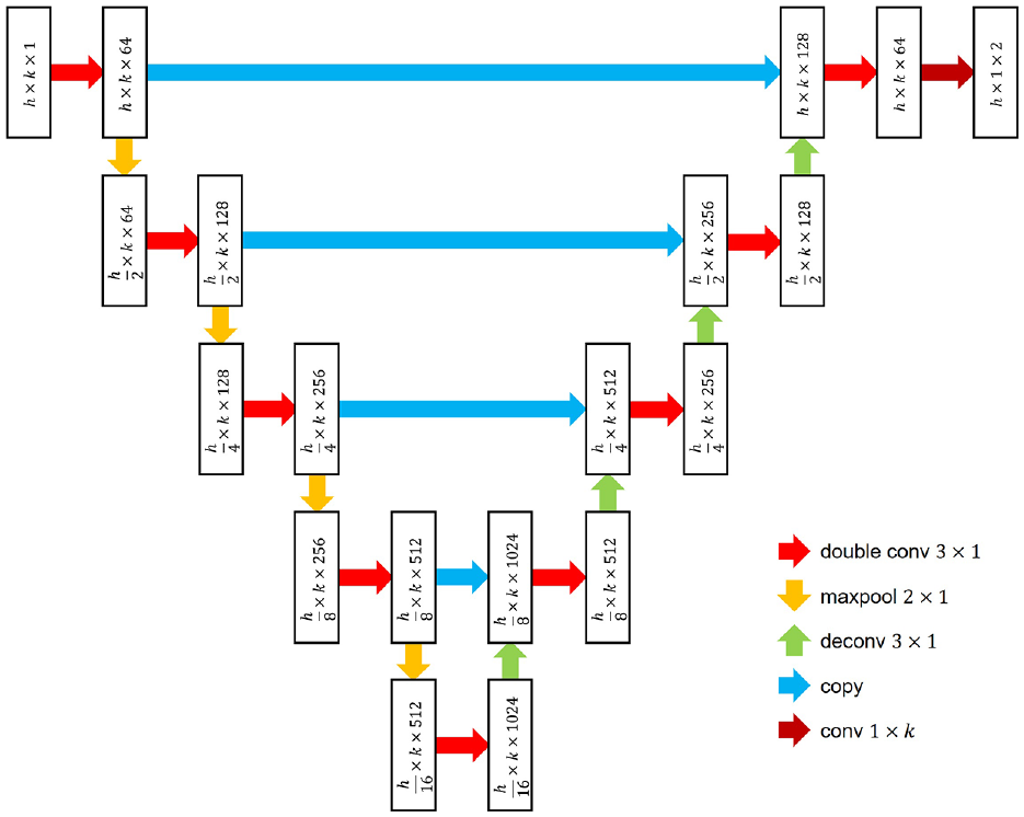
The proposed network.
The proposed network has the same structure as U-net, but the details are different. As shown in Figure 5, the feature map of the neural network is represented by rectangle, where the first number in the rectangle represents the height of the feature map, the second number represents the width, and the third number is the channel. The operational layers are represented by arrows.
These red arrows are double convolutional layers which performs convolution, batch-normalization, and rectified-linear-unit operations, and its main purpose is to change the channel, keeping the height and width constant. These orange arrows are the down-sampling layers, which are the maxpooling that halves the image size. These light green arrow are the up-sampling layer, which are the deconvolution layers, making the image size twice.
Although the structure of the proposed network is the same as U-net, some of the underlying operators are improved, which can make the neural network backpropagation and forward propagation faster and compatible with the annotations of object detection. The improvements are as follows:
In the convolutional layer, conv3 × 1 replaces conv3 × 3, which reduces the amount of parameters in the convolutional layer to 33%;
In the down-sampling layer, the size and stride of maxpooling operator are both
In the up-sampling layer, the stride of the transpose convolution operator is
The output layer with the dark red arrow is the convolution operator without batch-normalization and rectified-linear-unit. Its size changes from
The improvements can be seen visually in Figure 5. The width of the map does not change during the process, always equal to k. the size of P is

Image postprocessing
The P becomes
It is easy to extract the intervals that are continuously equal to 1 in Q. Suppose
The laser stripes can be extracted by a suitable threshold, and the threshold is described as:
Where the vector V1 and D1 are the values and indices of the largest elements along j-axis, respectively,
Any element of R is denoted as i, if
The start and end points of the longitudinal tear are denoted as

Result and discussion
In order to verify the performance of this method, three sets of experiments are designed: Firstly, the effect of k on the performance of neural network is analyzed in formula (4); Secondly, different optimized encoder-decoder networks perform longitudinal tear segmentation to compare the performance; Finally, the improved U-net compares the performance with the classical deep object detection. About 2154 longitudinal tear images were acquired to form the sample library, and 10% of these images were the validation set and the rest were the training set.
Performance of different Topk parameter
The parameter k of Topk is determined to make the longitudinal tear segmentation is the best. MIOU (Mean intersection over union) and DICE (Dice coefficient) are applied to evaluate the performance of the task. FCNs, Segnet, U-net, and Deeplabv3+ are selected as a comparison group, and they need to be improved besides U-net.
The structure of the three networks is similar to the U-net, then their improvement is also similar to the U-net. The improvement can be summarized as the height and width of the feature map change at the same time in the original, however only the height changes and the width remains the same in the improvement. The training optimizer is the RMSProp (Root Mean Square Prop), which has two parameters: learning rate and weight decay. The network is trained with learning rate = 10−4, weight decay = 0.0005.
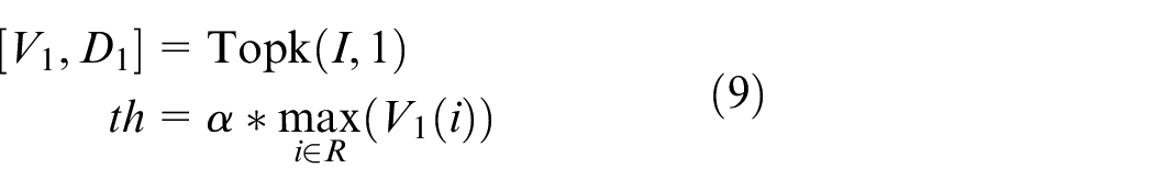
The performance of the four improved networks with different parameters of formula (4) is shown in Figure 6. The horizontal coordinate indicates the parameter k of Topk, and the vertical coordinate indicates the precision, which includes DICE and MIOU. The red and blue lines indicate the DICE and MIOU of the validation set, respectively; The green line and the magenta line indicate the DICE and MIOU of the training set, respectively. On the whole, the evaluations are poor when k is less than or equal to 3, and the evaluations become better and tends to be stable when k is greater than or equal to 7. Therefore, the k equal to 16 is an approximate optimal solution, then the batch size is set to a very large value during training to speed up the training speed, and the batch size set to 512 for Figure 6.
Performance analysis of four improved networks with different parameters after 100 epoch: (a) Im-FCNs, (b) Im-Segnet, (c) Im-deeplabv3+, and (d) Im-U-net.
The loss curves of the four improved networks are shown in Figure 7 when k is equal to 16. After 20 epochs of training, the loss functions of the four improved networks stabilize, and the loss of Im-U-net is minimized which is approximately 0.45. Because the output of the improved neural networks are one-dimensional vectors, the training converges quickly, and the loss function values are stable.
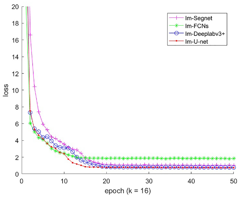
Loss function curve for training.
Table 1 shows the detailed of evaluation of the four models when k = 7 and 16. When k is equal to 16, the complexity of models is counted, then FLOPs is the amount of floating point operations and Params is the number of parameters of the network. Im-U-net is the second simplest in Table 1 which is slightly behind Im-FCNs; However, the performance of Im-FCNs is the worst in Figure 6;
Detailed evaluation of four improvement networks (k = 7 and 16).
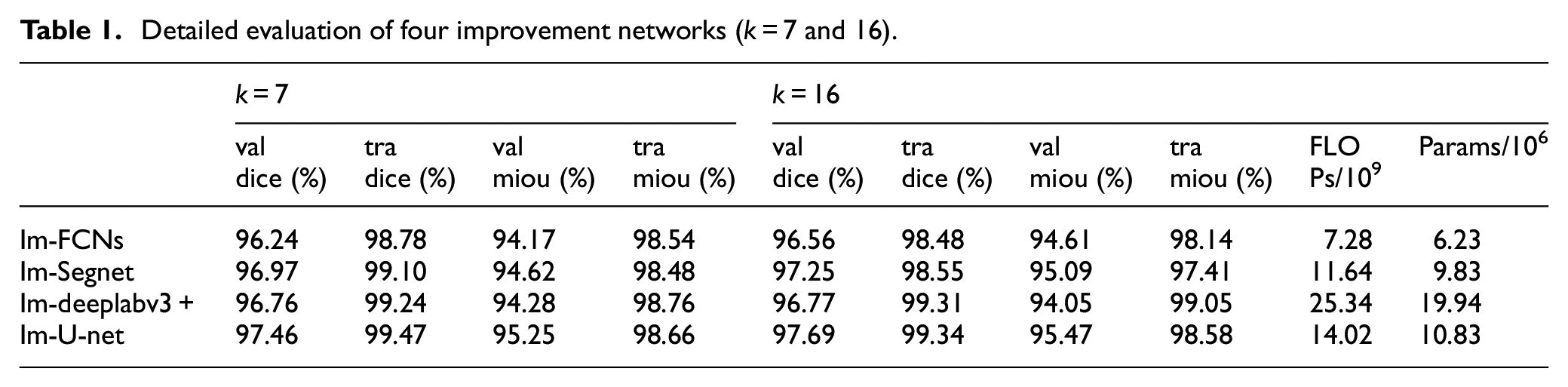
Figure 6(b) shows that the evaluations of Im-Segnet appear to fluctuate; Table 1 shows that Im-deeplabv3+ has better evaluations in the training set, but the evaluations are worse than Im-U-net in the validation set.
Thus, the proposed method occupies less GPU memory, converges quickly and stably, and the overall performance of Im-U-net is the best.
In order to visualize the inference results of the improved networks, the detection results presented in Figure 8. Each image has five line segments, and the five line segments are True Ground and Q(i) in equation (8) for the four improved networks. The first and second figures are characterized by small tear sizes, so Im-FCNs detection fails in the first graph and both Im-FCNs and Im-Segnet detection fails in the second figure. The third and fourth figures are characterized by larger tear sizes, so the improved networks all detect correctly.
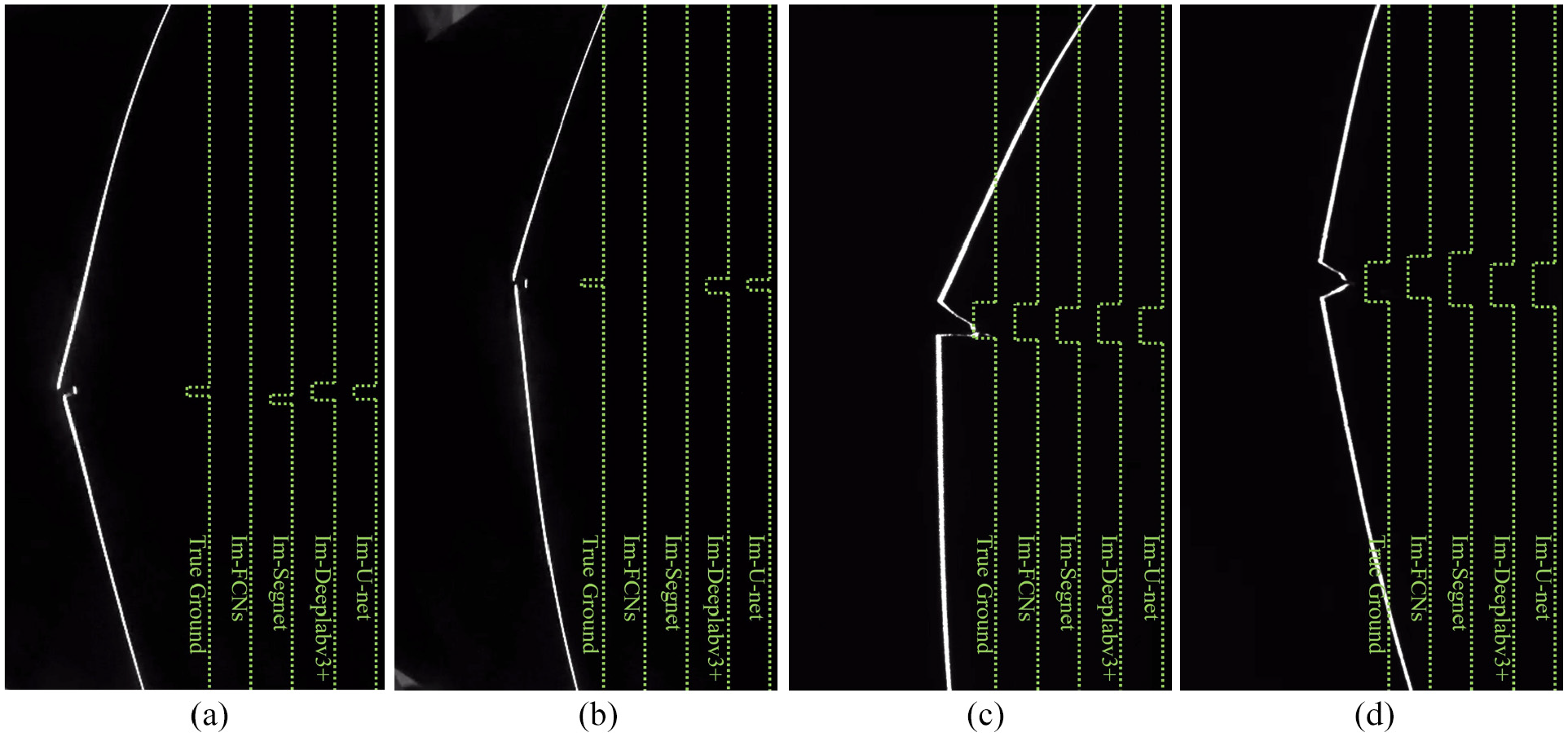
Inference results for different improved networks.
Figures 9 and 10 show the image preprocessing for the four images. The resolution of the original image is 704 × 400, and after preprocessing the matrices V and D in formula (4) both have a resolution of 704 × 16, so the information compression rate is 8%. The V represents the gray scale of the laser stripes and the D represents the spatial. As can be seen in Figures 9 and 10, there is still redundancy and the compression rate is further reduced when k is taken to a smaller value.
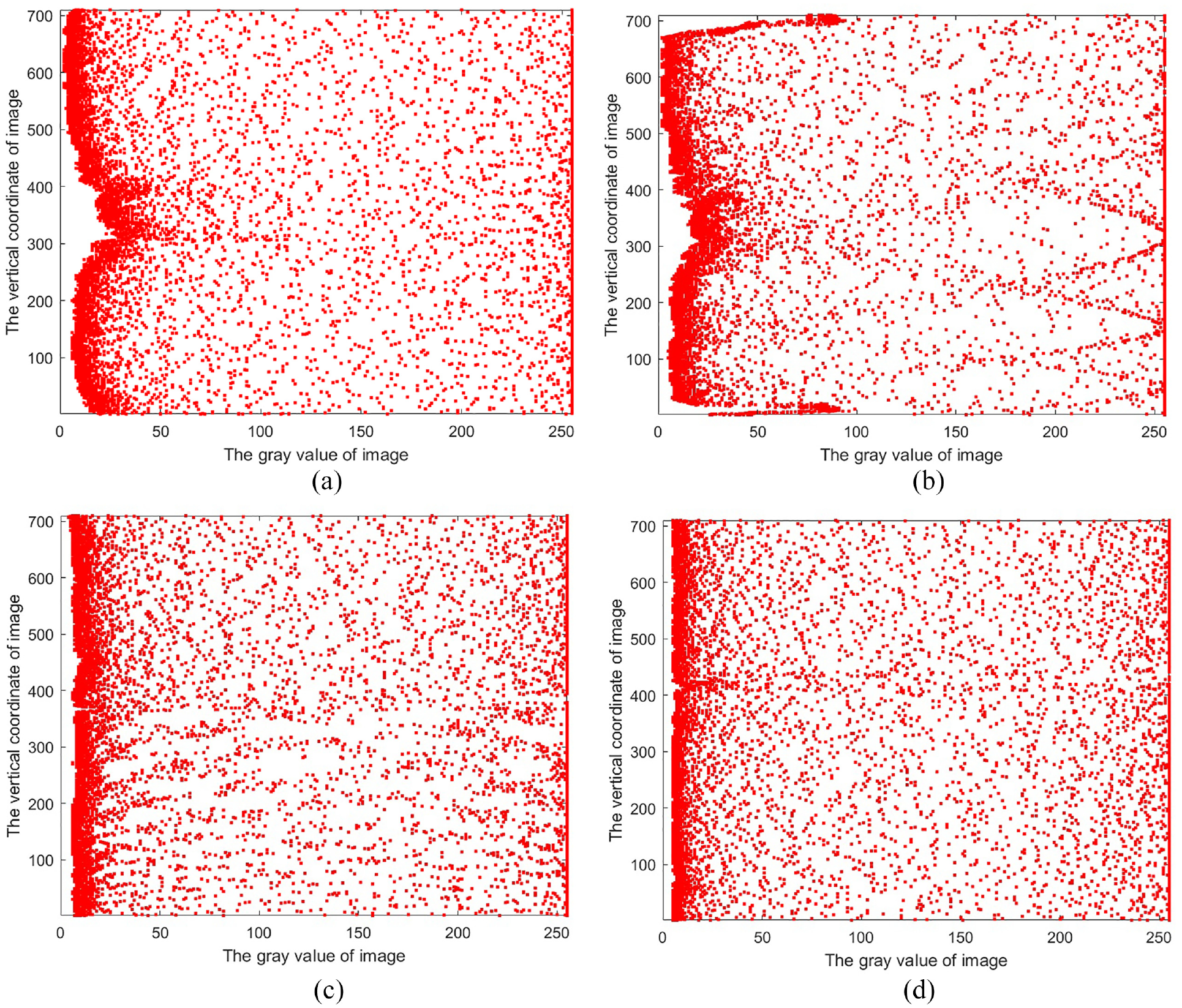
The matrix V is schematized in formula (4) when k is equal to 16.
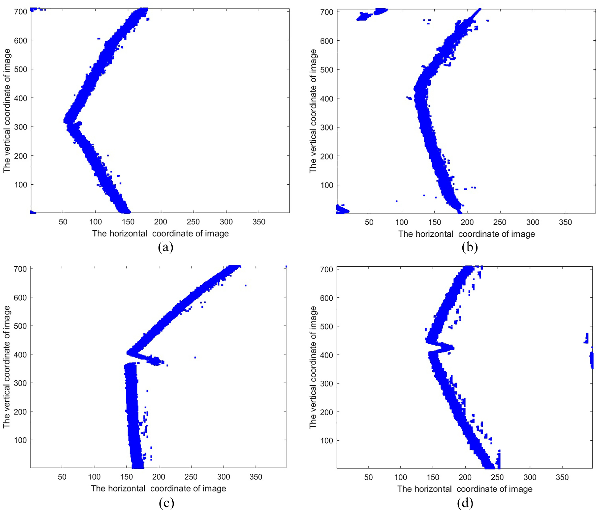
The matrix D is schematized in formula (4) when k is equal to 16.
Performance of longitudinal tear detection
After the inference of Im-U-net is calculated, the external rectangle of the longitudinal tear is detected by formulas (8)–(10), so that they can be easily compared with deep object detection,26,27 which can be divided into two categories official version and mobile version,28–30and the mobile version is characterized by small model and fast operation, but relatively low accuracy. The 208 positive samples in the validation set were used for this task. The comparative experiments are shown in Table 2.
Comparative experiments of different methods.
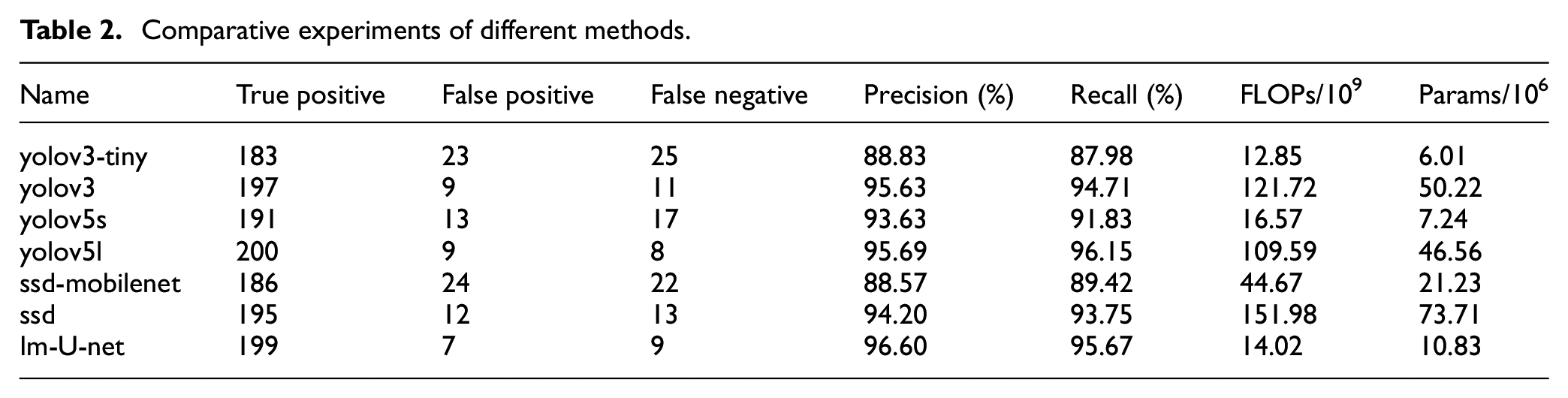
Im-U-net and yolov5l ranked the top two in terms of precision and recall, but the FLOPs and Params of Im-U-net are much better than yolov5l. Although yolov3-tiny has the lowest complexity, it has poor precision and recall.
Two conclusions are summarized in Table 2: (1) The way the training samples are labeled is simplified. Im-U-net which is compatible with the training samples for object detection belongs to semantic segmentation, and the others belong to object detection. (2) Im-U-net has the best overall performance.
Im-U-net is a 5-layer structure which contains four down-sampling and four up-sampling, and it can be compressed to speed up computation. The compression scheme is to reduce the number of layers to 4, then the number of sampling layers become 3. Similarly, the networks with a 3-layer structure can be built, and their structure is shown in Figure 11. The results of the ablation experiments for different networks are shown in Table 3.
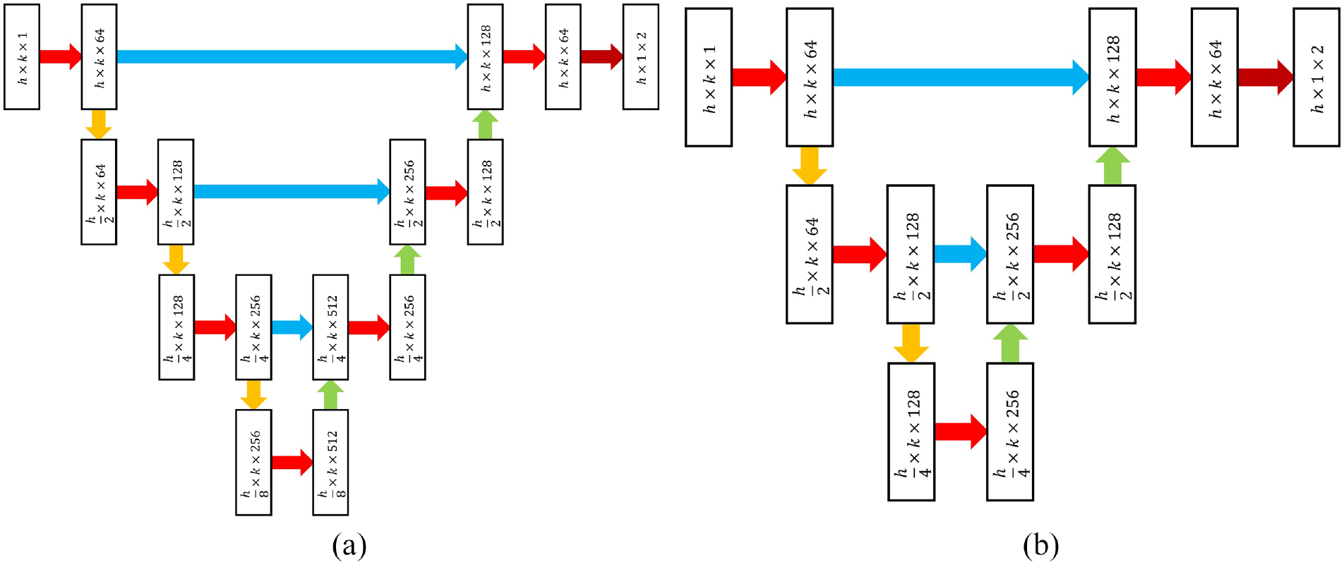
Compression of the improved network: (a) 4-layer structure and (b) 3-layer structure.
The ablation experiments.
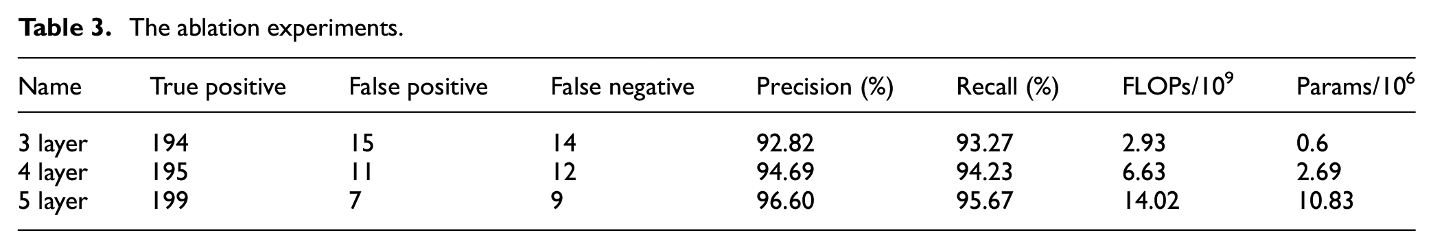
Using the 5-layer network as a standard, 4-layer structure has a small decrease in precision and recall, but the FLOPs and Params are reduced by 52.71% and 75.16%, respectively; The FLOPs and Params of 3-layer structure are reduced by 79.10% and 94.46%, respectively.
Mining equipment must meet the intrinsically safe type, so the processor is low power consumption. Belt conveyors run at high speeds, and the frame rate of image processing is required to be as high as possible, so 3-layer and 4-layer networks can be applied for low power consumption and high frame rates.
Industrial trials
We have conducted industrial trials in Guizhou Rongxiang coal mine. Three belts with tears were intercepted, each with a length of approximately 2 m. These belts were mounted on workholding fixture to simulate belt conveyor. Five images of longitudinal tears at different locations were collected for each belt, for a total of 15 images. The each length was measured manually according to the laser line guidance. The measuring tool was a vernier caliper with a minimum accuracy of 0.02 mm.
Tear detection equipment was developed and installed in the field as shown in Figure 12. The FPS (Frames Per Second) of the industrial camera is 170 and the processor is the rk3568 from Rockchip Micro. The FPS of the proposed method ported to the processor is about 52 for the 5-layer network, about 73 for the 4-layer, and about 84 for the 3-layer network. In order to balance the efficiency and accuracy of the tear detection, the 5-layer network was used as the detector for industrial trials.
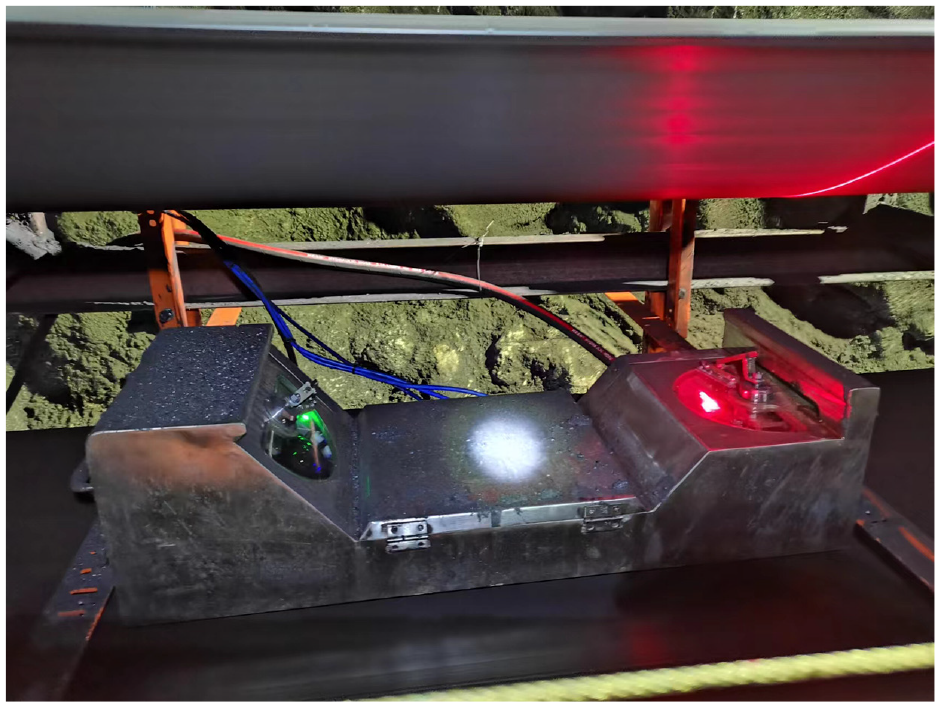
Industrial trials.
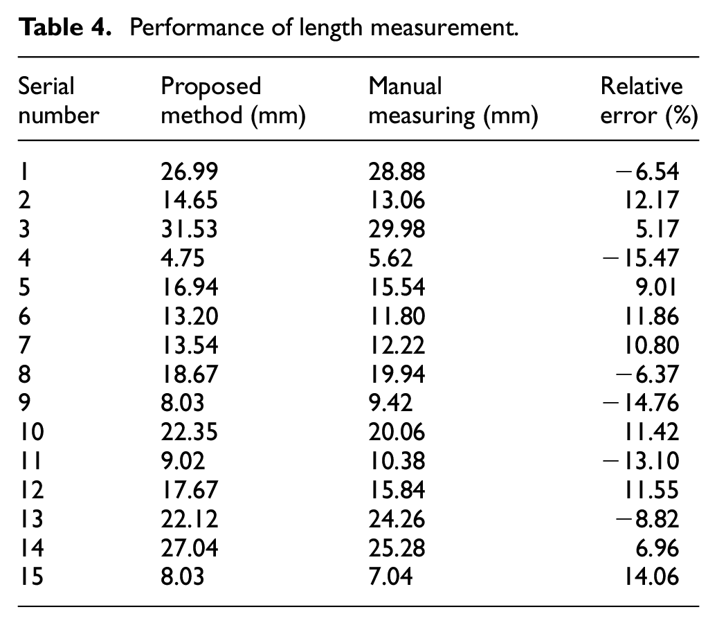
Table 4 shows the results of the length measurement. Manual measurements are considered as true values, then the extreme value of relative error is −15.47%. We have analyzed three main reasons for the relative error. First, the belt is elastic, and slight contact is prone to deflection during the manual measurement, so the manual measurement causes the relative error; Second, the width of each pixel in the image is about 0.213 mm after manual counting of 15 images, which is determined by the camera parameters, so the minimum accuracy of the pixel is 0.213 mm; third, the external rectangle is not possible perfectly describe the longitudinal tear during the sample labeling.
Performance of length measurement.
We also verified the effectiveness of the method during belt conveyor operation. The belt is stationary, and the longitudinal tear detection device was moved relative to the belt, and the relative speed not less than 3 m/s. In this state, manual measurements fail, but it is possible to determine that there is no blurring or trailing in the image.
Figure 13 shows the results of industrial trials. The laser emitter is a complementary light device, and industrial cameras capture high definition images without blurring due to motion or lack of light. The numbers in the upper left corner are the length of tear, which are calculated by formula (11). The red pixel is the longitudinal tear detection result, which is Q = 1 in formula (8), and the red pixels are shifted to the right in order not to obscure the original image. Thus, the results can be compared visually.
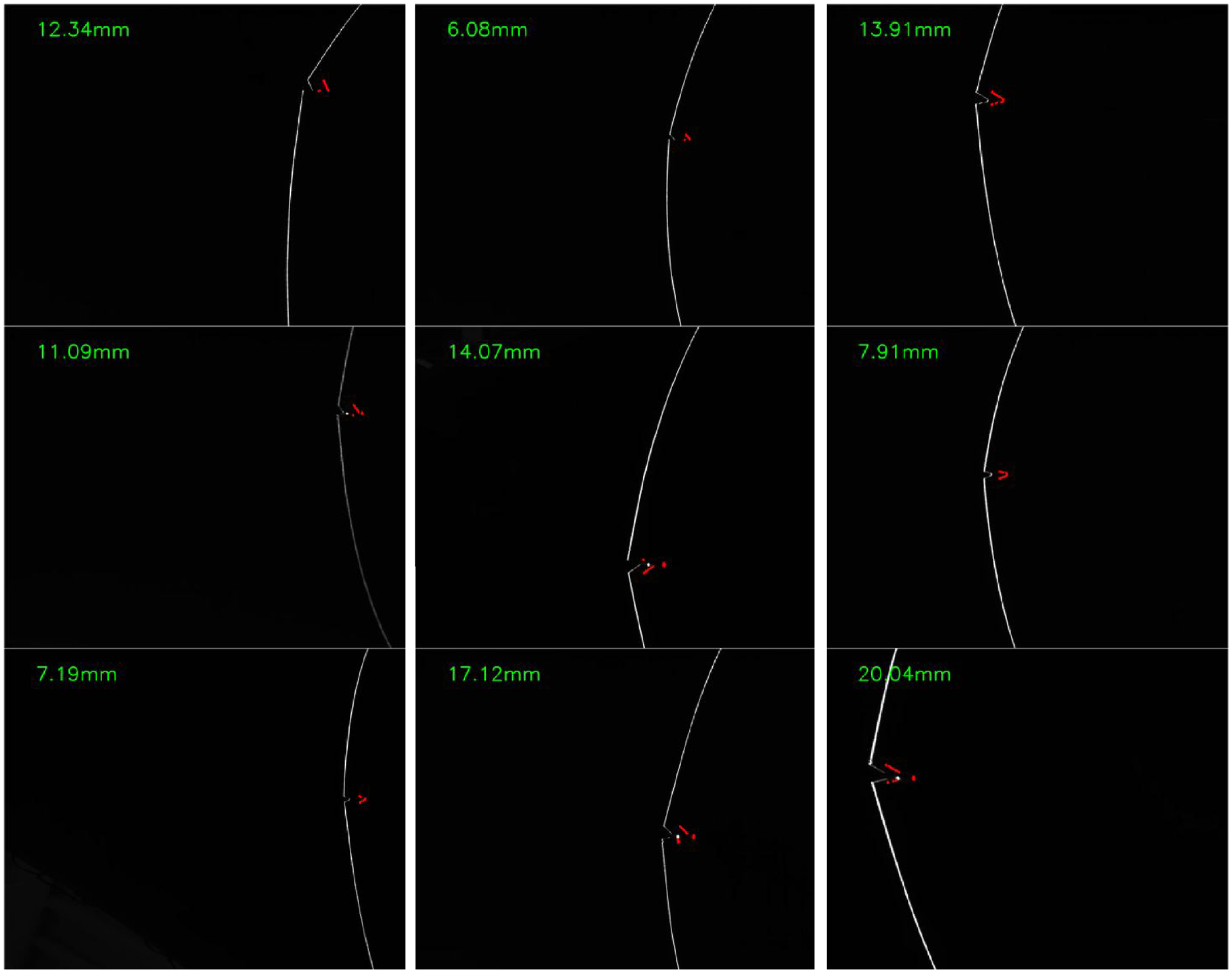
The results of industrial trials.
Conclusions
In this paper, a longitudinal tear detection for conveyor belts based on Encoder-Decoder networks is proposed. The proposed method is divided into four steps: image acquisition, image preprocessing, neural network, and image postprocessing. Image acquisition is a line structured light, then image preprocessing based on the Topk method can effectively extract the features of the conveyor belt. These features reduce the GPU memory usage and the batch size can be set to a large value when the model is being trained or inferenced. The improved neural network is proposed to complete the semantic segmentation of the longitudinal tear image, which is compatible with annotations for object detection. In the image postprocessing, the rectangle and physical width of the tear are determined. The experimental results show that this method effectively reduces the network size and operation speed in high precision. In the validation set, the DICE and MIOU of the improved network are 97.69% and 95.47%, respectively; the recall and accuracy of the detection for longitudinal tears are 96.60% and 95.67%, respectively. In industrial experiments, the extreme value of relative error is −15.47%, and the image does not appear blurred or trailing when the movement speed is about 3 m/s.
The purpose of this study is to enhance the detection of tears in belt conveyors with low speed and normal width. However, it is important to acknowledge that there are various types of belt conveyors and conveyor belt shapes, which can affect the installation and imaging quality of longitudinal tear detection. To further develop this method, the next step in the work plan is to conduct industrial trials on different types of belt conveyors. This will enable the optimization of the line structured light device in various belt conveyor settings, as well as the investigation of optimization algorithms in more complex environments. Additionally, it is important to note that the current sample set for longitudinal tears is insufficient. Therefore, in order to effectively improve the performance of the tear detection algorithm, it is necessary to collect more samples during later industrial trials.
Footnotes
Declaration of conflicting interests
The author(s) declared no potential conflicts of interest with respect to the research, authorship, and/or publication of this article.
Funding
The author(s) disclosed receipt of the following financial support for the research, authorship, and/or publication of this article: This work was supported by the Science and Technology Innovation Fund Key Project of China Coal Technology Engineering Group (Project No.: 2022-TD-ZD001) and Key Research and Development Projects of CCTEG Chongqing Research Institute (Project No.: 2022ZDXM02).
Data availability statement
Data sharing not applicable to this article as no datasets were generated or analyzed during the current study.