
Abstract
As photovoltaic energy is clean, renewable, and less noisy, it is increasingly integrated into the grid. This integration aims to overcome energy deficits and get rid of pollution from conventional sources. In this paper, a two-stage configuration of PV energy conversion to a three-phase grid has been studied. The control of this configuration can be divided into two parts, such as DC bus control and AC bus control. The DC bus is controlled by MPPT control. The AC bus is controlled by DC link voltage control, phase-looked loop control, and voltage source inverter control. The contribution in this study aims to improve the quality of energy injected via a new hybrid approach to MPPT control. The proposed control is a combination of robust sliding-mode control and incremental inductance. Unlike conventional hybridization, the proposed control estimates correct the error upon entry of the conductance incremental control. This correction provides an adaptive incremental step for increment conductance control. The proposed control is compared with three other controls under MATLAB/Simulink. Such as incremental conductance, variable step size incremental conductance, and conventional hybrid MPPT incremental inductance-sliding mode control. The simulation results show a remarkable minimization of the ripple phenomenon and the chatter phenomenon. Thus, the quality of the energy injected into the network is improved, such as by reducing the total harmonic distortion of the current and increasing efficiency.
Introduction
Renewable energy resources have become the best solution for energy problems nowadays, such as energy deficits and energy pollution. They are thought to be the greatest ways to satisfy energy requirements. In recent years, the management of these resources has greatly improved due to the high price of oil and the harmful effects caused by conventional energy sources on the planet.1,2 Particularly, photovoltaic energy has advanced significantly as a renewable energy source. It is regarded as a particularly efficient way to address the demand for sustainable, clean energy.
3
Both a freestanding setup and a grid-connected configuration are possible for the incorporation of this energy.3,4 Grid-connected photovoltaic systems are expanding steadily across the globe. The steady decline in operating costs and the installations’ straightforward design are to blame for this rise. Additionally, government energy policies support the generation of renewable energy. The market for grid-connected photovoltaic systems is expanding globally due to all of the aforementioned factors. In fact, the International Renewable Energy Agency (IEA) estimates that in 2019, the total global capacity of grid-connected PV systems will be roughly 576.3 GW.
5
This paper studies the PV grid-connected system in a three-phase grid under a two-stage transformerless configuration. The first stage is the boost converter, while the second is a voltage source inverter (VSI). To adjust for reactive power and total harmonic distortion (THD), the VSI inverter is used in conjunction with an LCL filter. Two components, such as DC bus control and AC bus control, make up the system’s control. The control of the DC bus is generated by the maximum power point tracking (MPPT) control. The control of the AC bus is realized in the
Numerous MPPT approaches are developed in the literature.10–13 These methods can be split into three parts: conventional methods, soft computing methods, and hybrid methods.14,15 The first part’s control is simple to install and low in complexity, but it has several flaws, including slow response time and ripple. The second part’s control is more sophisticated, has superior speed, more accuracy, and minimal ripple, but is expensive. In the third control, a combination of MPPT methods is used in order to assume the same benefits with each strategy. The hybrid strategy typically relies on conventional techniques combined with a soft computing method16,17 or on two soft computing techniques.18,19 In practice, the techniques most accepted in the industry are the incremental conductance (IC) method and the perturb and observe (P&O) method.20,21 Because it has a lower ripple and faster response time than the P&O approach, the IC method is employed in this study.
22
To optimize the outcome, however, the IC approach must be improved. Numerous enhancements to this strategy are suggested in the literature.23–25 Some approaches act directly on the incremental step of the duty ratio of the IC control. These approaches adopt an increment step proportional to the
Therefore, for control to be successful, a constraint must be minimized without creating another one. While the conventional IC-SMC hybrid technique has reduced ripple, it also causes chattering. In this study, we offer an alternative configuration of this hybrid technique to jointly reduce the two phenomena listed below. Consequently, the quality of energy injected into the grid improves as the two phenomena are minimized. For this reason, the contribution in this paper is to produce the adaptive step size for the IC method. The adaptive step size is generated by the SM control in order to be injected into the IC control. The SM control is limited in the discontinuous part, which is considered an adaptive step size increment for duty ratio in the IC control. This new hybrid approach can be called sliding mode-incremental conductance (SM-IC) control. The proposed control is tested in MATLAB/Simulink under changing irradiation. It is compared to the conventional IC method, the variable step size of IC method (VSS-IC), and the hybrid IC-SMC conventional method. The comparative results show notable improvements in chattering phenomena, ripple phenomena, minimization of THD, and improvement of inverter efficiency.
After this introduction, there are four sections that make up this paper. The system’s configuration and design, including the LCL filter, boost converter, and PVG generator designs, are explained in the first section. The AC and DC bus controls are described in detail in the second section, where a novel hybrid MPPT strategy between the IC technique and SMC is proposed for DC bus control. The final result is evaluated and explained in the third section. Ultimately, in order to resume the results of this study, a conclusion is required in the fourth section.
System design
The boost converter and the VSI inverter are two conversion stages that are a part of the two-stage architecture. From the photovoltaic generator (PVG), the active power is injected into the grid through an LCL filter after these two-stage conversions. The boost converter is utilized in order to increase the voltage generated by the GPV to the reference DC link voltage
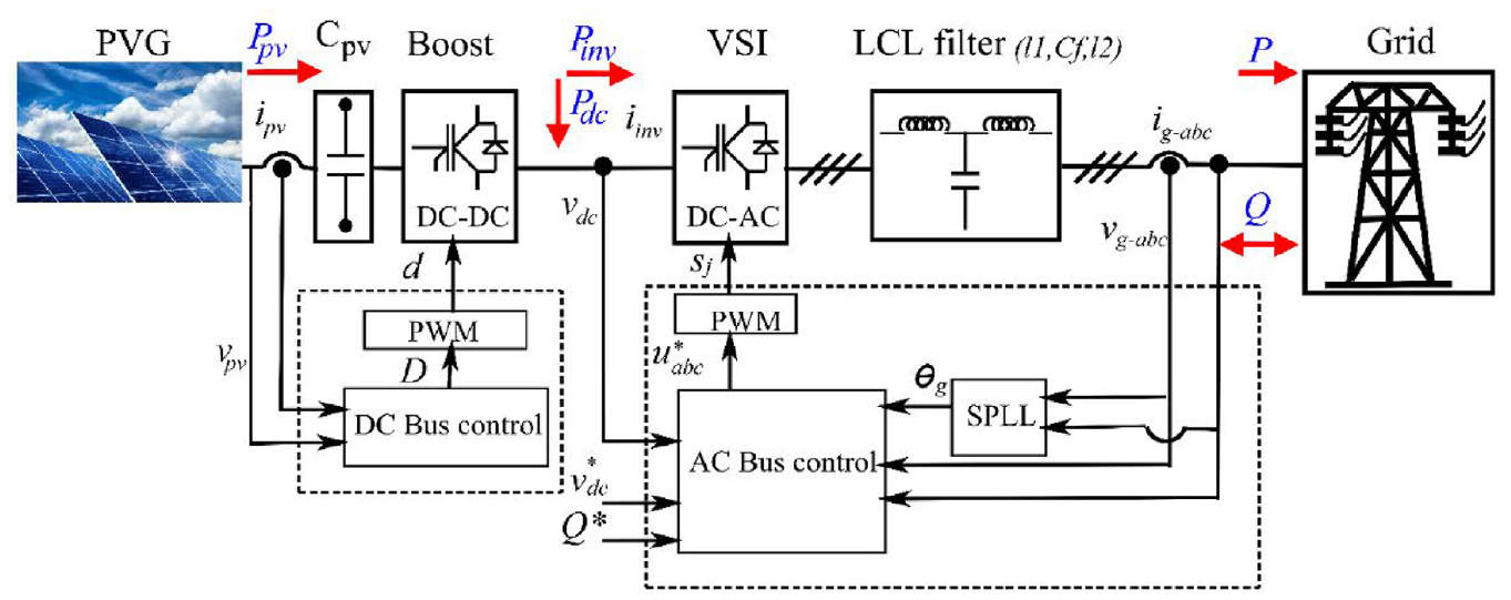
System configuration.
PVG design
Given that the standard boost converter has a gain of roughly
PVG design.
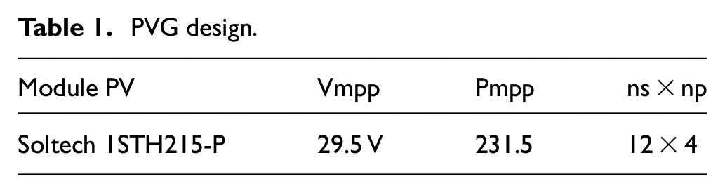
Where

Boost converter design
According to Figure 2, the boost converter’s switch component is made up of four elements, including the input capacitor filter
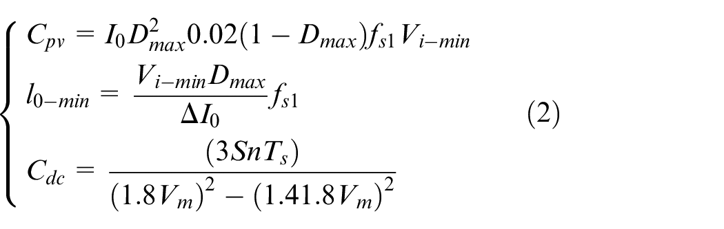
where,
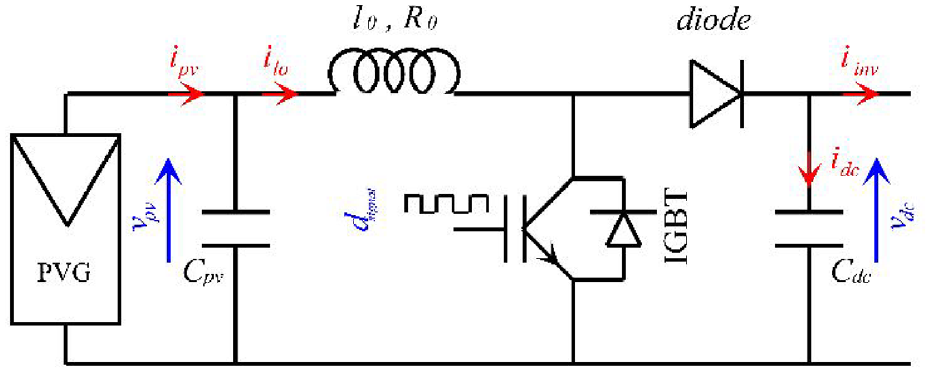
Boost converter design.
LCL filter design
In order to minimize the values of THD and reactive power, the voltage source inverter is used with an LCL filter. Numerous passive filters, including the L, LC, and LCL filters, are used in literature. However, the LCL filter is better than the LC filter due to its superior filtering performance and reduced cost, size, and weight. 39 The connection between the VSI inverter and the LCL filter is shown in Figure 3.
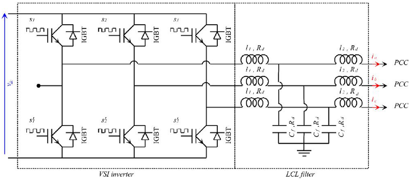
VSI inverter and LCL filter design.
The parameters of the LCL filters are deduced from many variables, such as rated power
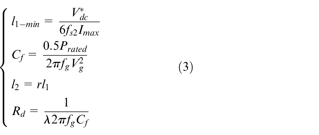
where
The linear load’s cumulative power is as follows:

Control system
To make the system’s control more clear, it is divided into two major parts, such as DC bus control and AC bus control.
DC bus control
The DC bus control is governed by the MPPT controller. The principle of this controller is to track the maximum power point of the PVG at each instant to generate the duty ratio corresponding to the boost chopper. In this paper, we will use the incremental inductance as the base of the MPPT controller. The IC method is widely used because of its simplicity and easy implementation. Here, the IC control is used in four scenarios, which are cited in Figure 4. Such as conventional IC control, variable step size IC control (VSS-IC), IC optimized by conventional sliding mode control (IC-SM), and IC optimized by a new proposed sliding mode approach (SM-IC). In the proposed control, the SMC is used only to generate an adaptive step size for the IC method.
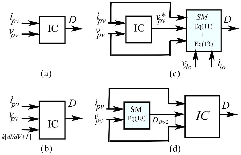
MPPT: (a) IC, (b) VSS-IC, (c) IC-SMC, and (d) proposed control SMC-IC.
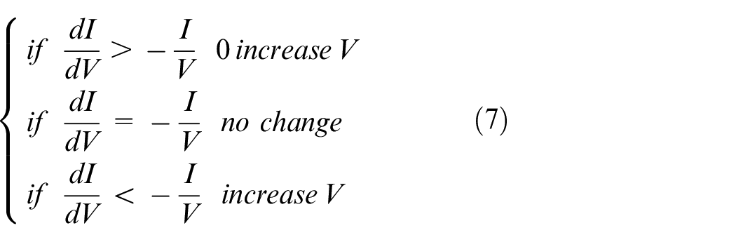
IC method
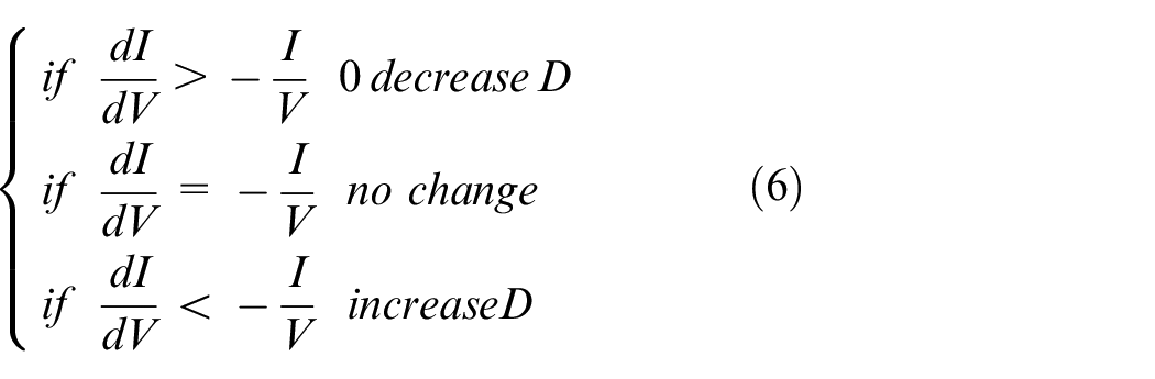
In the IC control, the MPP depends on the derivative of

At MPP
Hybrid method: IC-SMC
The hybridization between the robust control SMC and incremental conductance IC aims to realize another robust control that minimizes the oscillations of the IC method. This hybrid approach is composed of three steps 41 :

So the sliding surface is as follows:

where

where

where
According to the modeling of the boost converter under its two states on and off, the control signal is obtained from the following system:
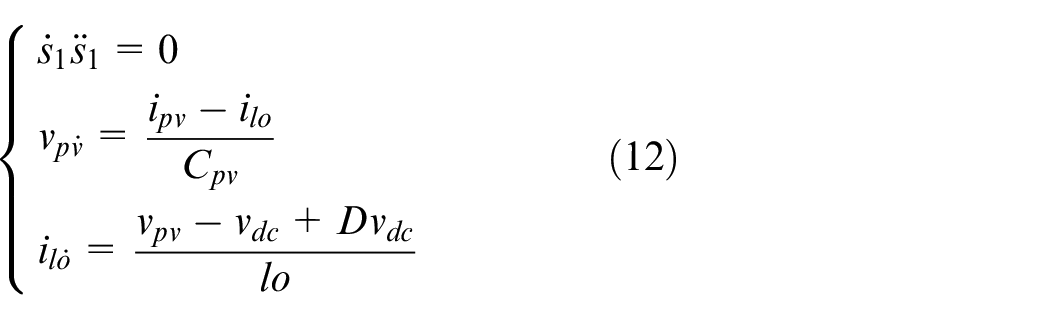
Finally, the equivalent part


The guarantee of convergence control is obtained by:

From the equations (10) and (16), we must choose
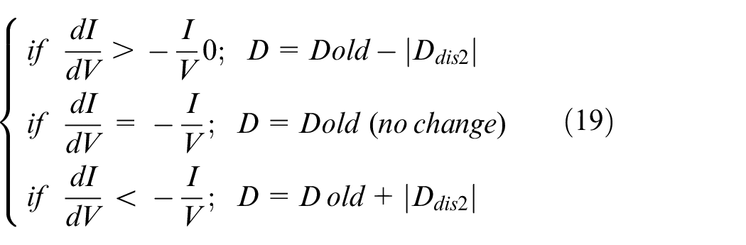
Proposed SMC-IC method
The proposed control designates the contribution to this paper. It is composed of two step:

A sliding surface is made as follows:

So, the discontinuous part is given as follows:

where

The guarantee of convergence control is obtained by:

From the equations (18) and (21), we must choose
AC bus control
AC bus control consists of three elements: DC link voltage controller, which has the role of generating the reference power that is injected into the VSI inverter. PLL controller, which has the role of synchronizing the input phase of the VSI inverter and the output phase of the grid. VSI controller, which generates the reference voltage signals in order to control the VSI inverter.
DC link voltage controller
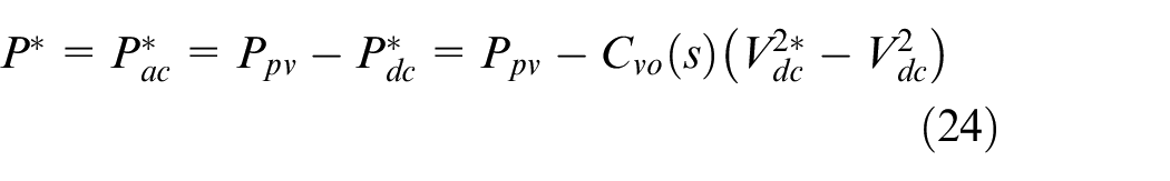
From the energy stored in the DC link capacitor

Assume that VSI inverter losses are insignificant

Via the substitution of the equations (22) and (23) we can determine the reference power injected into the VSI inverter that is cited in Figure 5.
where
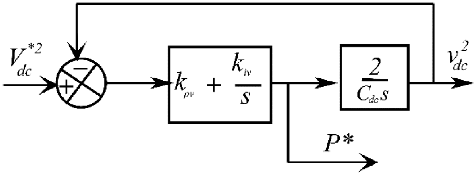
DC link voltage controller.
SPLL controller
A Phase-Locked Loop (SPLL) is a control system that generates an output signal whose phase is related to the phase of an input signal. In the context of PV grid-connected systems, PLL is used to synchronize the inverter’s output with the grid’s voltage and frequency.
42
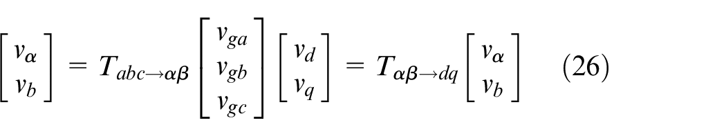
The balanced voltages of the three-phase grid in
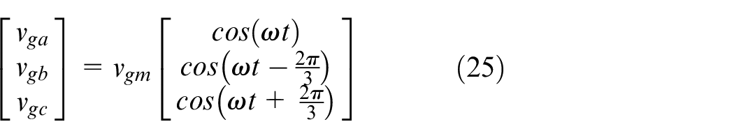
The transformation of these voltages from frame
When synchronization between the input and output phases is achieved (

The previous estimate implies a proportionality between the components in the

The second term

If grid synchronization is attained, we can write:

As a result, the grid voltage phase can be locked by closed-loop feedback control. Figure 6(a) represents the structure of the SPLL module deduced from the equations above. To facilitate the extraction of parameters from the PI controller, the SPLL module can be simplified into a classic PLL module, as shown in Figure 6(b).
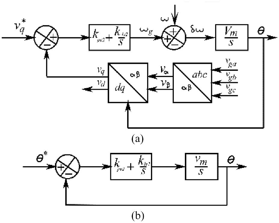
(a) SPLL and (b) simplified SPLL.
VSI controller
Several inverters, including VSI inverters, current source inverters (CSI), impedance source inverters (ZSI), and others, are described in the literature as being utilized in PV three-phase grid connections. For single-stage setups without a DC-DC converter, ZSI is advised. Although the CSI inverter is more expensive, heavy, and employed in low-speed ranges, it is marginally more dependable than the VSI inverter. Additionally, CSI only provides one command mode. The VSI inverter utilized in the design described above, on the other hand, is less expensive, less obtrusive, and provides two control modes, such as current control mode (CCM) and voltage control mode (VCM). 43
Because we aim at the high power factor, the current as the major control parameter, the reduction of short circuit currents, the reduction of total harmonic distortion, and the reduction of current transients, the VSI inverter is used in CCM mode in this work. 44
The
Since the LCL filter’s inductance impedance is much smaller than its capacitor’s impedance, the current flowing through the filter’s capacitor is also very small. From this estimation, we can infer:

From Figure 3, modeling in a
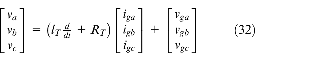
Where
In
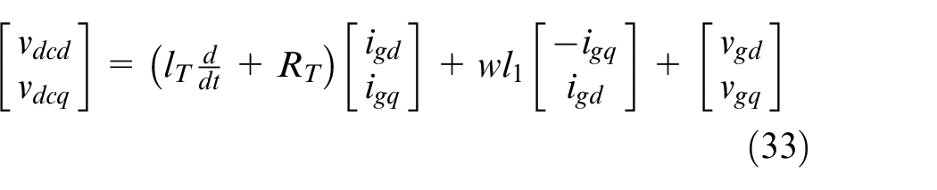
where
The current’s component parts in the

Hence, the transfer functions:

Finally, the VSI inverter control described in Figure 7 is defined by:
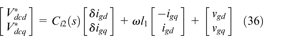
where
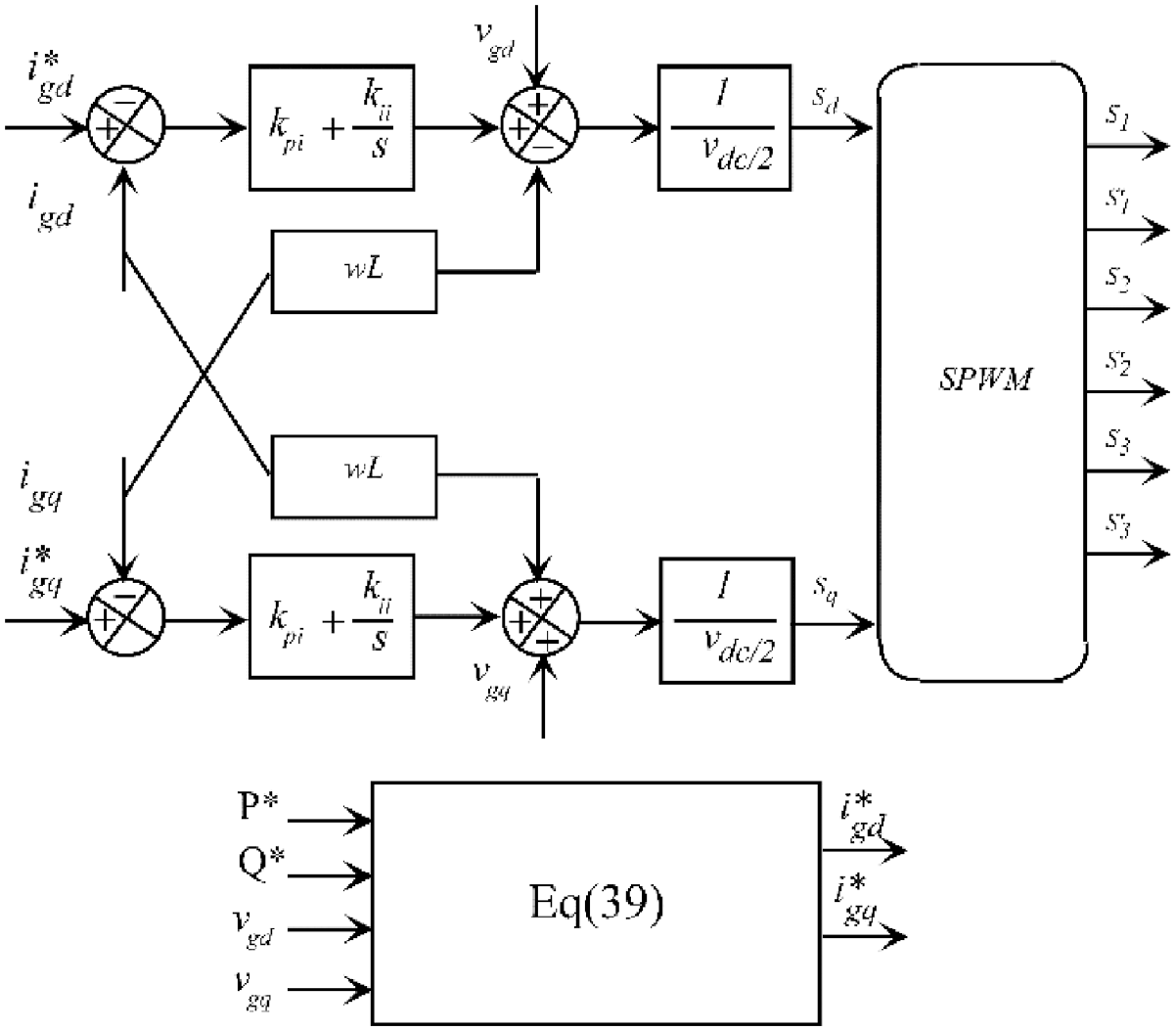
VSI inverter control.
The reference currents

When

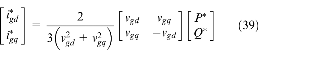
Reversing the preceding relationships reveals that the reference currents can be adjusted in the following ways to manage the injection of active or reactive power into the grid:
Performances evaluation
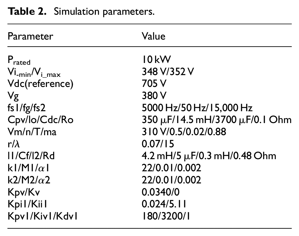
In this section, many simulations are drawn to demonstrate the performance of the proposed control and validate its correctness. The system components and parameters of controllers are indicated in Table 2. In this study, the test is done under rapid-change irradiation at a fixed temperature of T = 25. The irradiance profile is shown in Figure 8. The simulation time is chosen to show the response time of the studied controllers. The DC link voltage reference is fixed at 705 V. By injecting only the active power, the reference current
Simulation parameters.
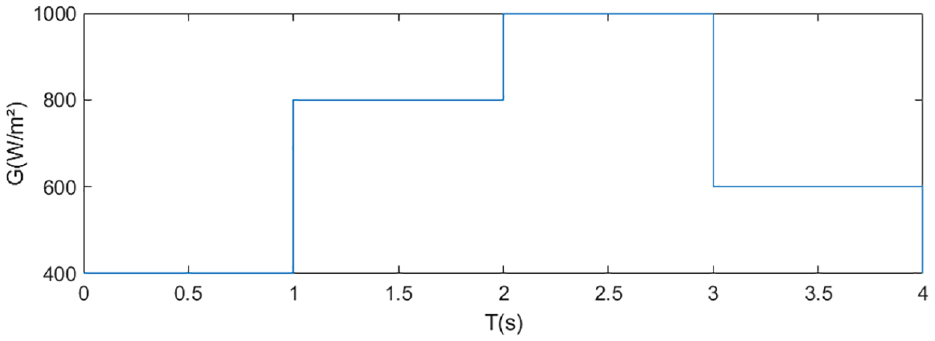
Irradiation profile.
Although conventional IC-SM control lessens ripple, it still has a serious chatter issue. Figure 9 which depicts the duty cycle’s evolution, exhibits the IC-SM control’s hard passage at time 3 s as a result of the phenomenon mentioned above. It is evident that the other control methods, as well as the control, are superior.
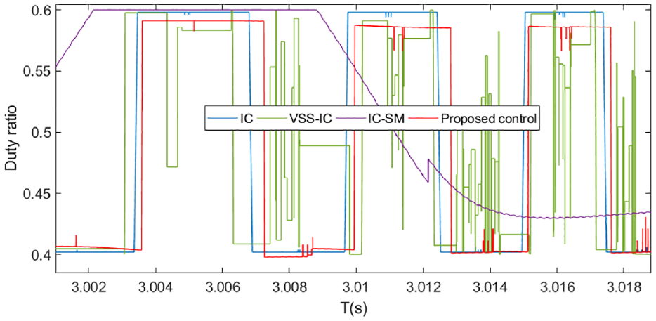
Evolution of the duty ratio.
Figure 10 shows the DC link voltage curve. In this curve, Zoom 1 and Zoom 3 show a low response time in conventional IC-SM control and a serious chatter phenomenon in transient conditions of the same control. For example, in Zoom 3, a drop of 10 V in DC link voltage was created at t = 3.02 s before stabilization. However, other control modes, such as IC control, VSS-IC control, and the proposed control, achieve a better response time and a very low chatter phenomenon. In the same figure, Zoom 2 shows a comparison of the ripple phenomenon between the four types of controls. In fact, the ripple value is 1.2 V for the IC control, 0.9 V for the VSS-IC control, 0.35 V for the IC-SM control, and 0.3 V for the proposed control.
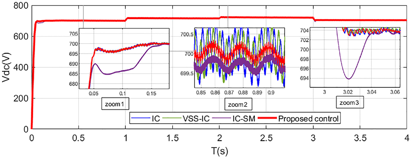
DC link voltage Vdc.
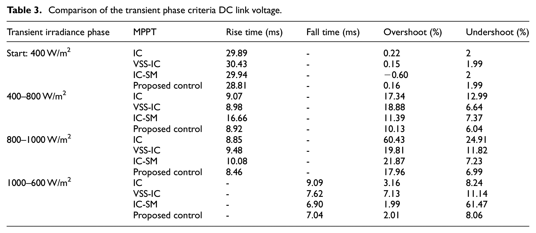
In order to go deeper into this comparison of DC link voltage, Table 3 shows a comparison of the transient phase criteria in DC link voltage. These criteria are such as rise time or fall time, overshoot and undershoot. All things considered, the comparison cited in this table clearly proves the improvement of these criteria by the proposed control at each transient phase.
Comparison of the transient phase criteria DC link voltage.
The SM-IC control is to provide optimized reference power for the inverter’s input. Figure 11 shows the reference power curve produced by the DC link voltage controller. In this curve, the Zoom 4 shows a clear classification of the ripple phenomenon, which absolutely enhances our proposed control. This result is also verified in Zoom 5, Zoom 6, and Zoom 7. The proposed control is to provide optimized reference power for the input of the inverter. Figure 11 shows the reference power curve produced by the DC link voltage controller. In this curve, the Zoom 4 shows a clear classification of the ripple phenomenon, which absolutely enhances our proposed control. This result is also verified in Zoom 5, Zoom 6, and Zoom 7. In these last zooms, it is also shown the minimization of chattering phenomena and improving response time.
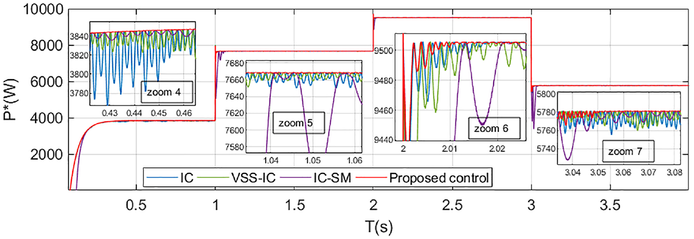
Reference active power P*.
The previous conclusions are also verified in Figure 12. This shows the grid power curve. Indeed, Zoom 10, Zoom 11, and Zoom 12 show a more flexible and faster transition of power in transient mode. Zoom 8 and 9 show a comparison of the first peak in the transient regime between the four types of controls. Overall, all these last significant zooms clearly prove the superiority of the proposed control.
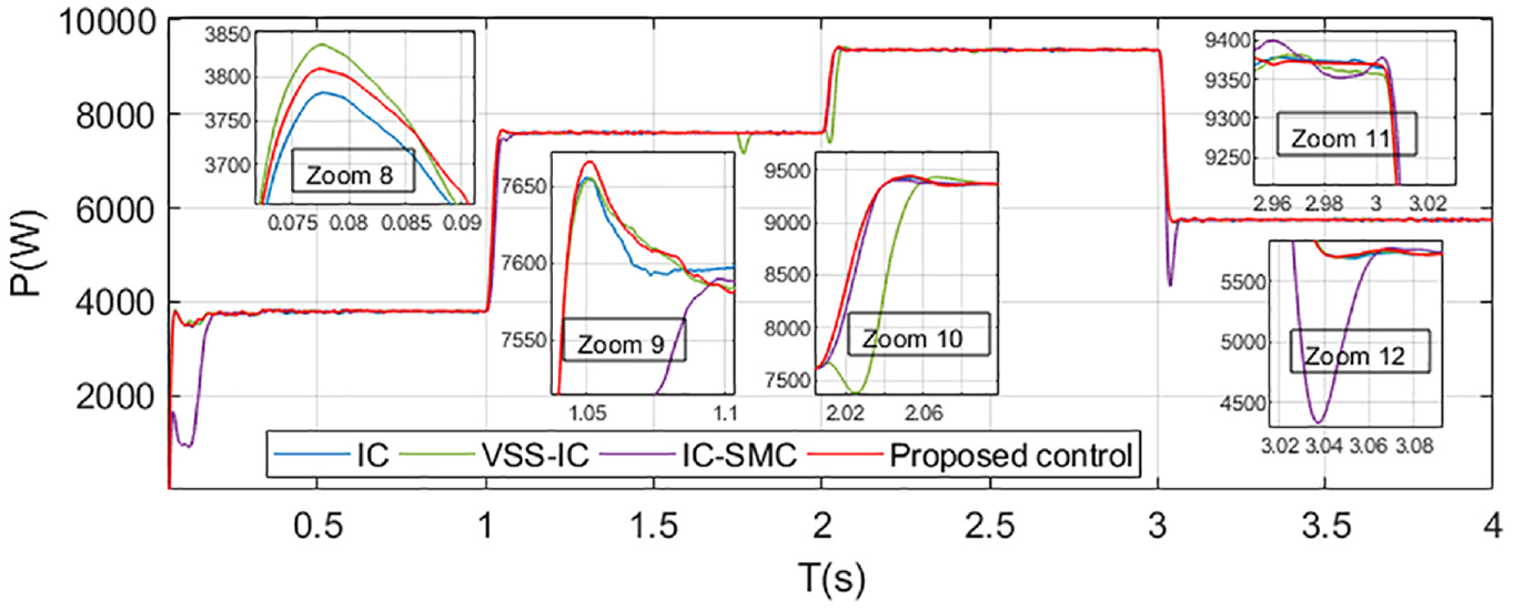
Grid active power P.
In the PV grid-connected system, we also aim to inspect the injection of reactive power, which must follow a targeted reference. Figure 13 represents the evolution of the reactive power Q, which does not exceed 5% of the apparent power S. This is respected for the four types of controls.
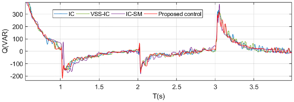
Grid reactive power Q.
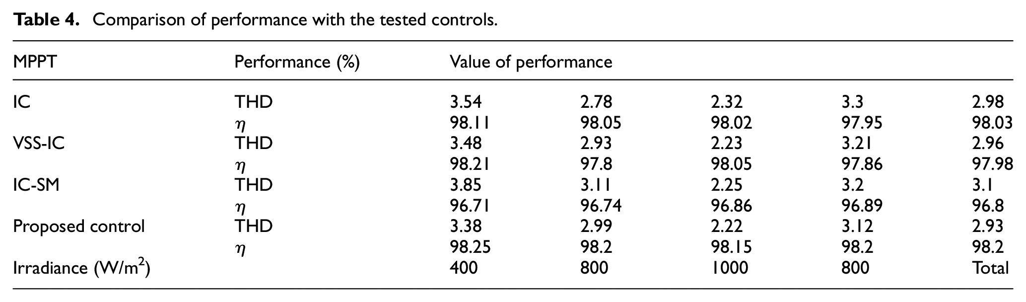
It is also necessary to assess the intended performances and how they affect the quality of energy fed into the grid. Tables 4 and 5 provide a summary of this evaluation. The first table represents a comparison between the proposed control and other controls tested in this paper. The second table represents a comparison between the proposed control and other controls cited in the literature, such as Particle Swarm Optimization (PSO), Modified Incremental Conductance (MIC), and Hybrid Incremental Conductance-Particle Swarm Optimization-Model Predictive Control (IC-PSO-MPC). Finding identical test circumstances in the literature is challenging. For this reason, we are limited in the configuration of a two-stage PV grid-connected three-phase system that includes a VSI inverter and boost converter. We have recorded the THD and the efficiency
Comparison of performance with the tested controls.
Comparison of performances with controls in the literature.

Conclusion
Grid-connected photovoltaic (PV) systems depend on MPPT control to optimize energy production by continuously changing the operating voltage and current to guarantee the system reaches its maximum power point. With the use of this control, energy yields can be increased, grid stability and integration can be improved, quick responses to environmental changes may be made possible, and system cost efficiency can be increased. In this paper The PV grid connected in a two-stage configuration is featured. The method under test is a new hybrid approach MPPT that combines sliding mode control and incremental inductance. In this case, sliding mode control is only used to produce an adaptive incremental step for the regulation of the incremental inductance. Three distinct control types are compared with the suggested control, including IC control, VSS-IC control, and IC-SM control. The simulation results show a reduction in the two phenomena called into question, such as the oscillation phenomenon and the chatter phenomenon. Thus, the improvement of the two phenomena by the proposed control resulted in a lowering of the THD and an increase in efficiency.
Footnotes
Acknowledgements
Not applicable.
Author contributions
The concept of the article was to optimize MPPT control by using a new hybrid approach between sliding mode control and incremental conductance control.
Declaration of conflicting interests
The author(s) declared no potential conflicts of interest with respect to the research, authorship, and/or publication of this article.
Funding
The author(s) received no financial support for the research, authorship, and/or publication of this article.
Data availability statement
No data were used to support this study.