
Abstract
Rehabilitation exoskeleton robots play a crucial role in restoring functional lower limb movements for individuals with locomotor disorders. Numerous research studies have concentrated on adapting the control of these rehabilitation robotic systems. In this study, we investigate an affine state-feedback control law for robust position control of a knee exoskeleton robot, taking into account its nonlinear dynamic model that includes solid and viscous frictions. To ensure robust stabilization, we employ the Lyapunov approach and propose three methods to establish stability conditions using the Schur complement, the Young inequality, the matrix inversion lemma, and the S-procedure lemma. These conditions are formulated as Linear Matrix Inequalities (LMIs). Furthermore, we conduct a comprehensive comparison among these methods to determine the most efficient approach. At the end of this work, we present simulation results to validate the developed LMI conditions and demonstrate the effectiveness of the adopted control law in achieving robust position control of the knee exoskeleton robot.
Keywords
Introduction
The world is undergoing a profound demographic shift characterized by the remarkable rise in the aging population over the past few decades. This demographic transformation, often referred to as population aging, carries profound implications for various facets of society, including healthcare, social welfare, labor markets, and overall economic productivity. 1 A key domain influenced by population aging is the mobility and functional abilities of older individuals, who experience natural declines in physical capabilities, such as reductions in muscular strength, motor neurons, muscle fibers, and aerobic capacity.2–5 As a response to these demographic changes and the pressing need to enhance the mobility and independence of older individuals, exoskeletons have emerged as a promising field of robotics and assistive technology. These wearable robotic devices are designed to augment or restore human physical capabilities by providing mechanical support, strength amplification, and motion assistance, and they have garnered significant attention and research interest due to their potential applications in rehabilitation, physical therapy, and assistance for the elderly and individuals with mobility impairments.6–8
Within the realm of exoskeletons, a specific focus has been placed on the development of exoskeletons tailored for rehabilitation purposes.9–11 These rehabilitation exoskeletons play a pivotal role in bridging the gap between therapeutic interventions and assistive technologies, as they provide both rehabilitative exercise training and support for daily activities. This convergence of rehabilitation and robotics has ushered in new possibilities for enhancing the lives of individuals with mobility impairments, enabling them to regain independence and actively participate in daily tasks. A critical determinant of the effectiveness of rehabilitation exoskeletons lies in their control systems.8,12–14 Control algorithms are instrumental in ensuring the safe and effective operation of these exoskeleton devices, facilitating seamless interaction between the user and the robotic system. The control system’s primary responsibility is to generate and coordinate the motions of the exoskeleton’s actuators to assist, amplify, or restore human movements with precision and efficiency. The success of rehabilitation exoskeletons hinges on the control algorithm’s ability to mimic and enhance the wearer’s natural movements while providing necessary support and assistance.15–19
Developing effective control strategies for rehabilitation exoskeletons is a multifaceted research endeavor, combining principles from robotics, biomechanics, and rehabilitation science.13,20–22 The intricate nature of human-robot interaction and the variability in patients’ physical conditions pose significant challenges in the development of robust and adaptive control strategies.23,24 Researchers and engineers are continuously exploring various control techniques and strategies to optimize the functionality and performance of rehabilitation exoskeletons. Personalized and adaptive control strategies have emerged as focal points in this field, aiming to provide efficient and precise control that seamlessly integrates the exoskeleton with the user’s body, thereby enhancing their mobility and quality of life. Furthermore, the integration of advanced sensing technologies, such as wearable sensors and inertial measurement units, has enriched the potential for developing sophisticated control strategies.17,23,25 These sensors offer valuable insights into the wearer’s gait, posture, and muscle activities, enabling the control system to adapt in real time based on the user’s intentions and needs. The incorporation of sensor data into the control algorithm fosters a more natural and coordinated human-robot interaction, facilitating more intuitive and fluid movements.
The control of rehabilitation exoskeletons represents a captivating multidisciplinary endeavor that harmoniously integrates principles from the diverse domains of robotics, biomechanics, and rehabilitation science. This harmonious fusion paves the way for continuous research and innovation in this ever-evolving field. The relentless pursuit of resilient and adaptable control strategies serves as the driving force propelling advancements in this dynamic arena. Hence, numerous studies have delved into diverse control strategies with a specific focus on improving walking assistance and gait rehabilitation.12,14,25–30 These endeavors contribute to advancing the field by offering insights into the multifaceted domain of lower limb exoskeleton control. These groundbreaking exoskeletons not only promise heightened stability during the rehabilitation process but also hold the potential to bestow individuals with mobility impairments a newfound sense of independence and an enriched quality of life. The paramount focus of this paper is dedicated to the formidable task of attaining meticulous position control within a powered lower limb exoskeleton, with a specific spotlight on the pivotal knee joint.31–35 Undoubtedly, the knee joint stands as a linchpin in fundamental activities such as walking and bearing weight, accentuating its pivotal role in the blueprint of exoskeletons designed for rehabilitation and assistance. Our primary mission revolves around the conception and deployment of a robust affine state-feedback controller, meticulously crafted to effectively preside over and stabilize the knee exoskeleton robotic system. The mastery of knee joint control stands as a linchpin in ensuring the precision and seamlessness of movements, ultimately bestowing users with heightened mobility and an amplified sense of independence.10,24,32,33
To accomplish our goal, we delve into the intricacies of the robotic system’s nonlinear dynamic model, which encompasses factors like solid and viscous frictions. These frictions wield substantial influence over the knee exoskeleton’s performance, rendering their inclusion in the control design process imperative. Employing an affine state-feedback control approach and harnessing the principles of Lyapunov stability theory, we introduce three distinct design methods. These methods allow us to establish a set of Linear Matrix Inequality (LMI) conditions governing the feedback gain of the proposed control law.31,36–38 These LMI conditions serve as robust safeguards for the knee exoskeleton system, ensuring stability and resilience even in the face of uncertainties and disturbances. In addition to theoretical analysis and design, this paper offers comprehensive simulation results validating the effectiveness of the LMI conditions and the proposed affine state-feedback controller. The simulations furnish compelling evidence of the controller’s capacity to maintain stability and robustness, reinforcing the credibility of our approach.
The main contributions of this paper can be succinctly outlined like so:
A robust affine state-feedback controller is meticulously crafted to ensure the stabilization of the knee exoskeleton robot. This controller is tailored to address the intricate nonlinear dynamics inherent in the system, taking into account pivotal factors such as solid and viscous frictions, uncertain parameters, and external disturbances affecting the knee-joint exoskeleton robotic system. The amalgamation of parametric uncertainties and external disturbances is encapsulated within a unified variable, termed the lumped disturbance.
Utilization of the Lyapunov approach, the S-procedure Lemma, the Young inequality, the Schur complement, the matrix inversion lemma, and judicious congruence transformations to formulate stability conditions in terms of LMIs via three different methods used to establish quadratic conditions on the boundedness of the nonlinearity presented in the dynamical model of the knee exoskeleton.
Enhancement of the stability conditions in LMI form through the introduction of optimization problems. These problems permit the maximization or minimization of two critical parameters: the maximum amplitude of the lumped disturbance and the parameter incorporated into the controller constraint.
Presentation of a series of numerical simulations validating the derived mathematical results. These simulations serve to illustrate the controller’s efficacy in compensating for the impact of the lumped disturbance on the knee exoskeleton system.
The subsequent sections of this paper are organized as follows: Section 2 delves into the description of the nonlinear dynamics of the knee exoskeleton and the formulation of the problem. Section 3 introduces the controlled dynamics and utilized affine state-feedback controller. Section 4 explores the design of LMI stability conditions through three distinct methodologies. Section 5 presents the results of the simulations, providing empirical validation of our approach. Finally, Section 6 concludes the paper while discussing potential avenues for future research.
Nonlinear dynamics of the knee exoskeleton and problem formulation
Description of knee exoskeleton system
In this comprehensive study, we embark on an illuminating exploration of the intricate nuances embodied by the knee exoskeleton, masterfully unveiled in the artfully crafted schematic showcased in Figure 1.
32
This knee exoskeleton epitomizes a design ethos meticulously honed around geometric precision, a testament to its engineering excellence in the quest for optimal functionality. Taking the form of a seated structure, it is a thoughtful creation engineered to grant unrestricted shank mobility, orchestrating the graceful symphony of knee joint extension and flexion. At
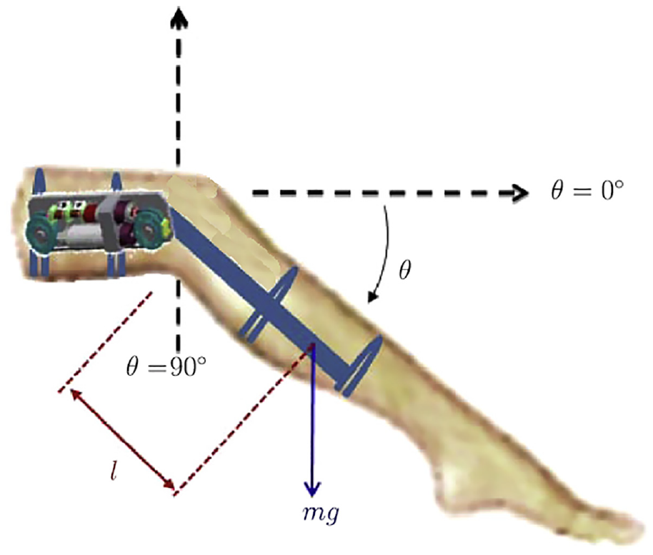
Geometric representation of the knee exoskeleton robot for the rehabilitation purposes (adopted from Rifaï et al. 32 ).
This ingenious exoskeleton springs to life through the fusion of two seamlessly interlinked segments, astutely poised at the knee joint’s epicenter, and seamlessly entwined through a pivotal rotational axis. The upper segment, an eloquent representation of the thigh, plays the role of a vital citadel, housing the actuator that powers the exoskeleton’s fluid motion. The lower segment, with painstaking precision, mirrors the shank’s distinctive attributes. To secure an impeccable fit, both segments clasp firmly onto the user’s lower limb, courtesy of adjustable straps. This meticulously crafted configuration breathes life into the knee exoskeleton, endowing it with the remarkable ability to faithfully replicate the knee joint’s natural sagittal plane rotational ballet.
In our unwavering pursuit of simplicity and astute motion management for the knee exoskeleton, we made a deliberate choice: the adoption of a single-degree-of-freedom robotic knee joint system. This strategic decision empowers us to channel our research endeavors toward the cultivation and rigorous scrutiny of robust control strategies. Our paramount aspiration finds its expression in the enhancement of stability and precision within the realm of lower limb rehabilitation, culminating in the provision of unwaveringly dependable and profoundly comfortable assistance to users. Our overarching mission unfurls the banner of a promising era, one marked by elevated mobility and an all-encompassing sense of well-being, where effective lower limb rehabilitation and assistance shine brightly on the horizon.39,40
Nonlinear dynamics of the exoskeleton robot
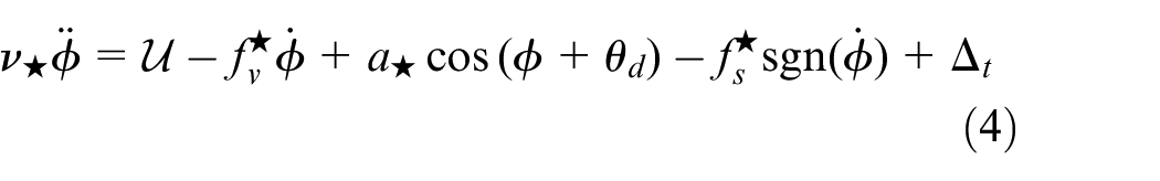
Taking into account multiple factors influencing the dynamic behavior of the exoskeleton robotic system, we can articulate its nonlinear dynamics as follows, incorporating the influences of both solid and viscous frictions:

In this context, the scalar value

where each component within the disturbance quantity
Δ pu corresponds to the contribution stemming from parametric uncertainties.
Δ ed accounts for the influence of external disturbances.
Δ ud encompasses the impact of unmodeled dynamics.
Δ hl signifies the contribution arising from the force exerted by the human leg.
Moving forward, we will make the following assumption regarding the total disturbing term
in the nonlinear dynamics (1).

This implies that the absolute magnitude of the total disturbance
This comprehensive representation (1) of the exoskeleton’s dynamics allows us to consider and address various factors affecting its behavior and control.
Considering the relationship
Desired controller at the equilibrium
After successfully positioning the knee exoskeleton robotic system at the desired state

Hence, in a state of equilibrium, we can express the desired control input

State space representation
Let’s define

In this model (7), the functions


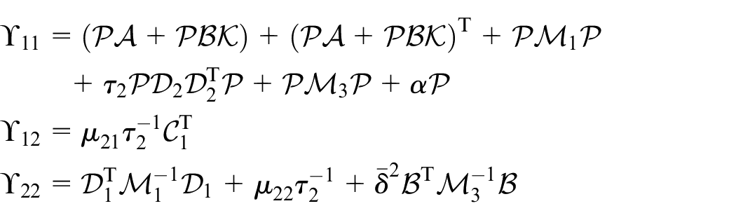
The following expressions represent the matrices
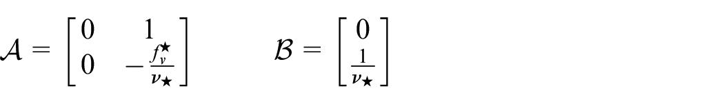
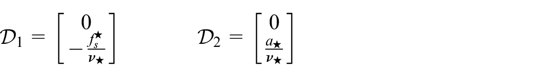
It is important to note that in the dynamical model (7), the non-linearities of the exoskeleton robot’s dynamic model are grouped into two nonlinear terms,
Problem formulation
Individuals facing mobility challenges stand to gain significant advantages from lower limb exoskeleton orthoses, potentially rekindling their mobility and enhancing lower limb functionality.14,41,42 This study places a specific emphasis on an actuated knee joint orthosis, chosen for its straightforward implementation and limited degrees of freedom. This orthosis model, capable of simulating flexion and extension motions of the knee joint in the sagittal plane concurrently, serves as the focal point of our investigation.
Recent years have witnessed a growing interest in the field of controlling lower limb exoskeletons, a domain that has increasingly captivated the attention of robotics researchers. 43 Our primary objective in this research is to develop advanced control strategies tailored for lower extremity exoskeleton devices designed to assist elderly individuals with essential standing and walking tasks.26,44,45
This research unfolds with a distinct emphasis on the control of a knee exoskeleton robot, specifically one equipped with a single degree of freedom, meticulously illustrated in Figure 1. Furthermore, in our unique approach, we amalgamate the rod and the foot into a unified rotational system at the knee joint level, treating them as a singular entity.
Hence, our primary mission embarks on the establishment of an effective control and a stabilization mechanism for the knee exoskeleton robotic system presented in Figure 1, and governed by its intricate nonlinear dynamics (1) or equivalently (7). To achieve this goal, we will use the Lyapunov approach and we will propose three methods to establish LMI stability conditions, empowering us to wield robust control over robotic systems, capitalizing on the insights gleaned from prior research in this dynamic arena.
46
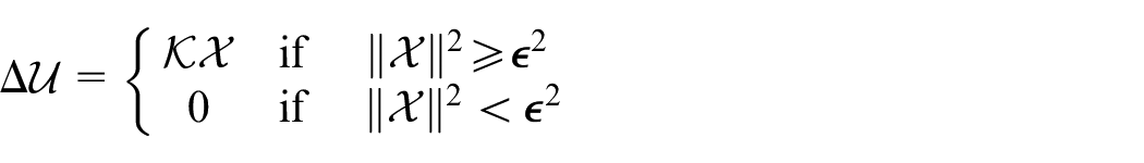
In the first approach to designing the LMI conditions, we assume that the squared quantity of the function
Moreover, in order to handle with these nonlinear functions
Adopted affine state-feedback controller and controlled dynamics
Utilized affine state-feedback controller
Our primary goal in this study is to achieve precise position control of the knee exoskeleton robotic system. To efficiently control the robotic system with its nonlinear dynamics (1), we propose an affine state-feedback control law.
This envisioned control law is defined by the following expression:

with
where here
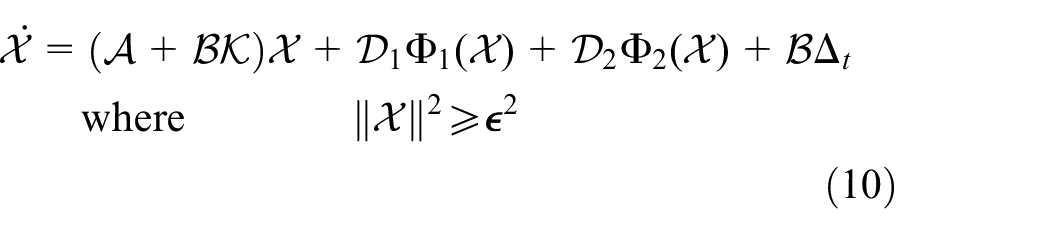
Controlled dynamic model
The previously suggested control law governs the nonlinear dynamic model of the knee exoskeleton robotic system, which can be formulated as follows:
Design of LMI stability conditions
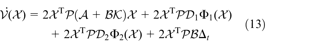
In this section, we focus on formulating an LMI condition for the feedback gain of the proposed controller (9). This controller plays a dual role in both controlling and stabilizing the knee exoskeleton robot. Our approach involves utilizing the Lyapunov technique to achieve this goal. Accordingly, we will adopt the subsequent candidate Lyapunov function:

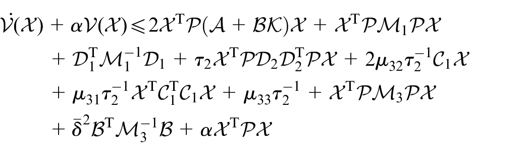
Subsequently, the time derivative of the candidate Lyapunov function can be expressed as follows:

Considering the controlled nonlinear dynamics (10), the expression (12) can be rephrased in the following manner:
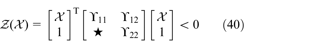
To further enhance the efficacy of the control outcomes, we introduce the subsequent criterion for achieving exponential stability:

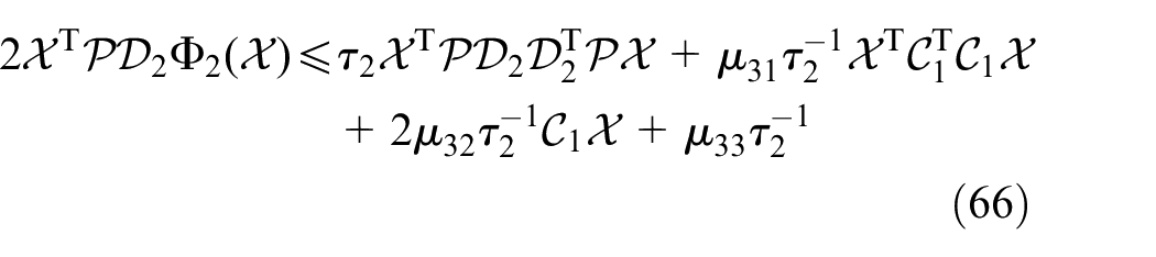
with
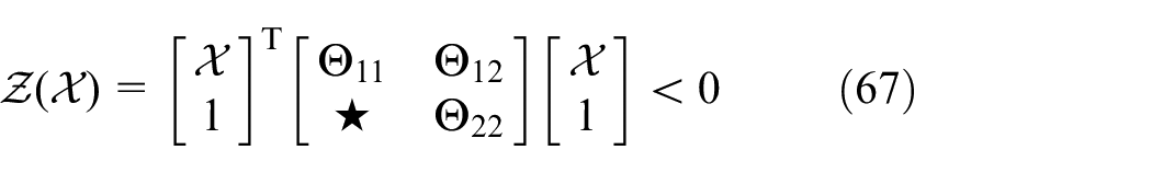
Furthermore, it is worth acknowledging that the constraint
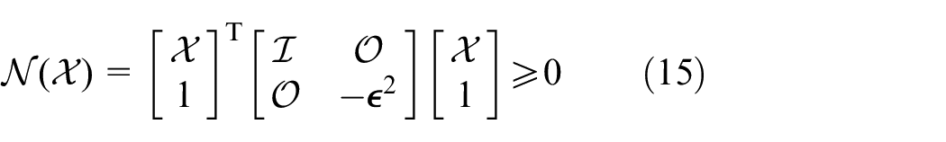
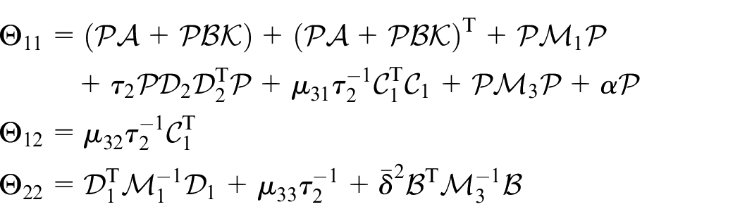
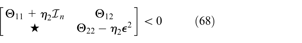
where here and in the following,
Subsequently, we will proceed to develop three distinct approaches for designing LMI-based stability conditions for the feedback gain
First approach for formulating LMI conditions
In the initial approach to designing the LMI conditions, we make the assumption that the function
By employing the Young inequality lemma37,47–49 on equation (13), it becomes apparent that:

where
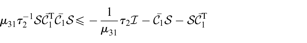
Moreover, relying on expression (8a), considering that

Consequently, given that

where
As
Moreover, we can demonstrate the subsequent set of inequalities:

Therefore, by extending the previous expressions, it is straightforward to derive the following inequality:

with

This leads to rewriting of the previously developed inequality as follows:

Furthermore, given that

where
Considering the constraint on

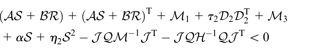
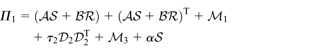
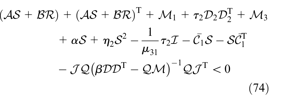
By replacing constraints (16), (19), and (20) into the resultant equation (13) and considering constraint (14), the following inequality may be constructed:
Let consider
with
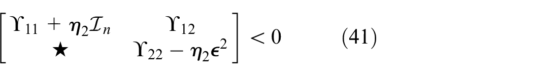
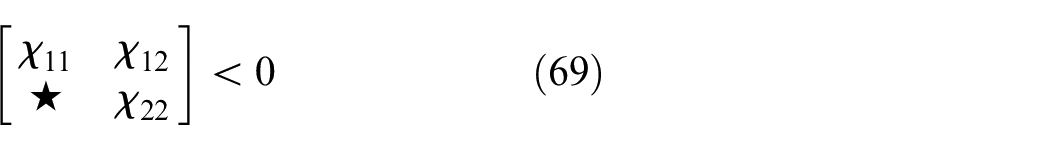
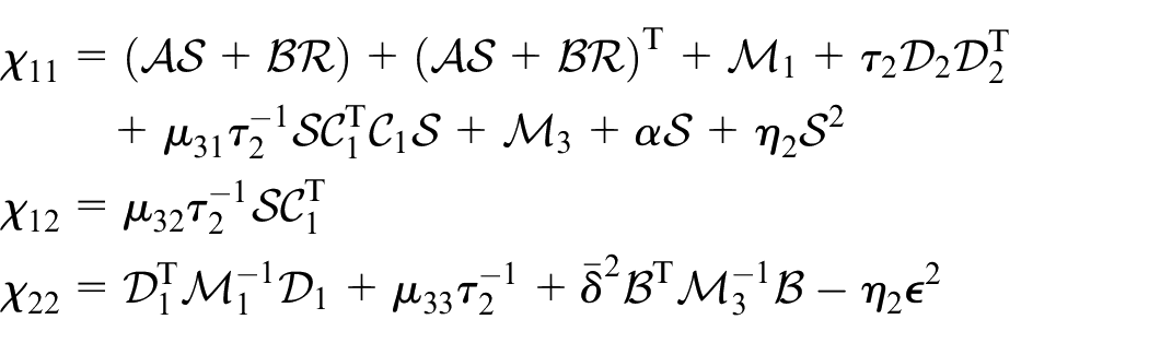
Employing the S-procedure lemma37,47–49 and incorporating the expressions (21) and (15), we formulate the subsequent stability condition:
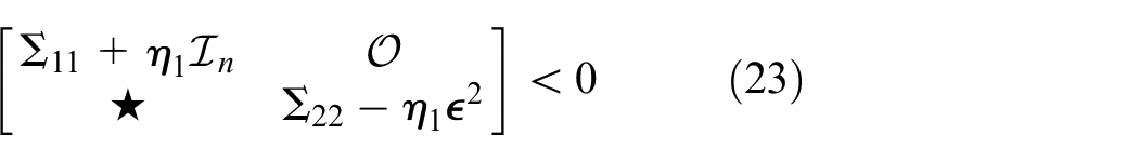
where
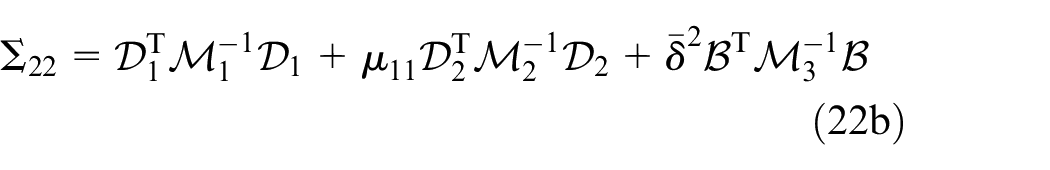
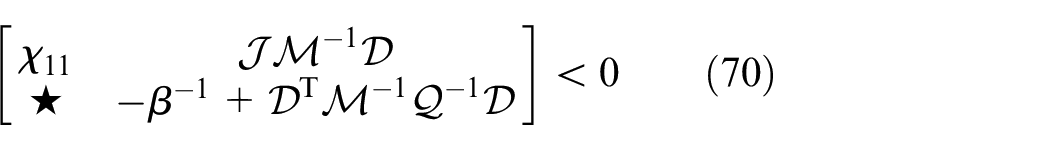
Derived from the matrix inequality in (23), we can demonstrate the ensuing pair of inequalities:
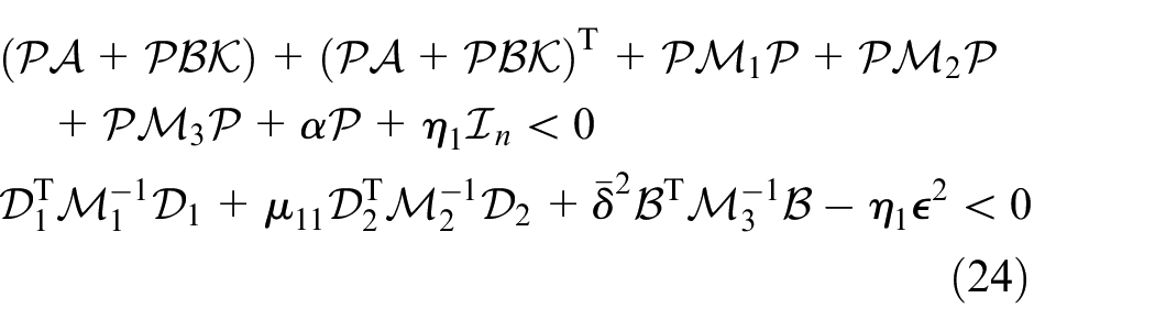
Subsequently, once the first extended condition in (24) has been multiplied on both the right and left sides with
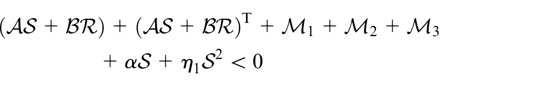
with

Setting
with
Additionally, by multiplying the second developed stability condition in (24) by
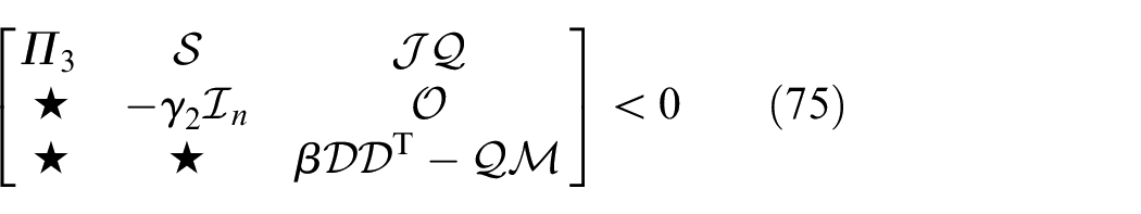
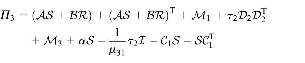
Applying the Schur complement and introducing the following new change of variables
It is crucial to highlight that

Therefore, the strategy to minimize
Evidently, the previous expression can be rephrased in the subsequent manner:

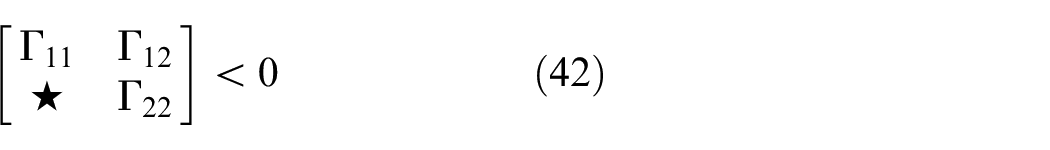
Using the previous expression and applying the Schur complement lemma, we derive the ensuing LMI stability condition:
where
Furthermore, it is important to highlight that

Hence, the objective to maximize

By utilizing the previous inequality and applying the Schur complement lemma, we can formulate the following LMI stability condition:
where
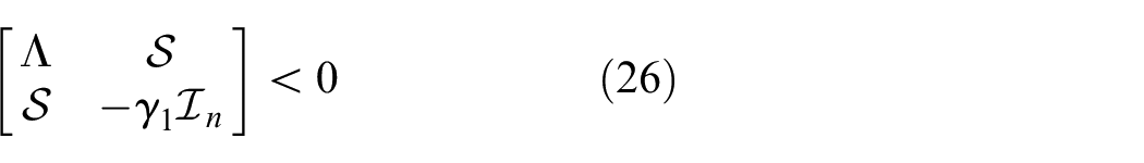
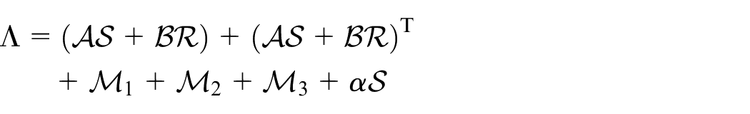
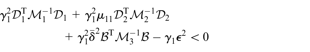
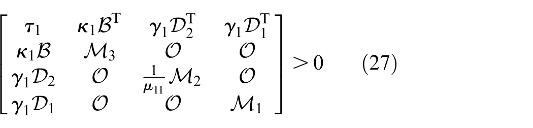
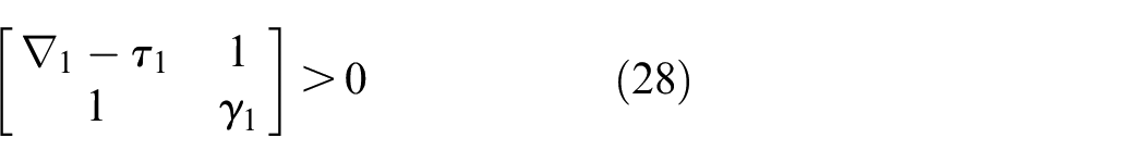
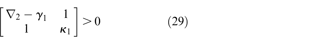
Consequently, the LMI stability condition outlined in (26), (27), (28), and (29) are derived. These conditions are characterized in terms of the unknown variables


where
As a result, the two constraints defined by (30a) and (30b) can be reformulated as follows:
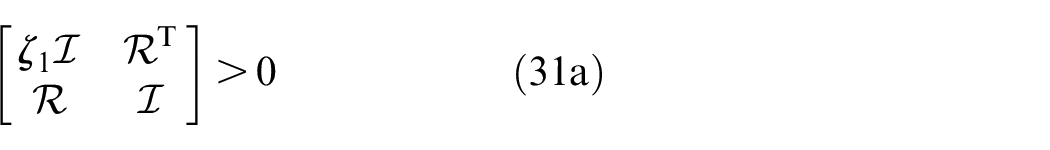
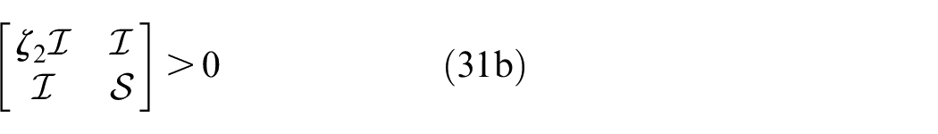
The two parameters
In the intended LMIs (31a) and (31b), the two parameters
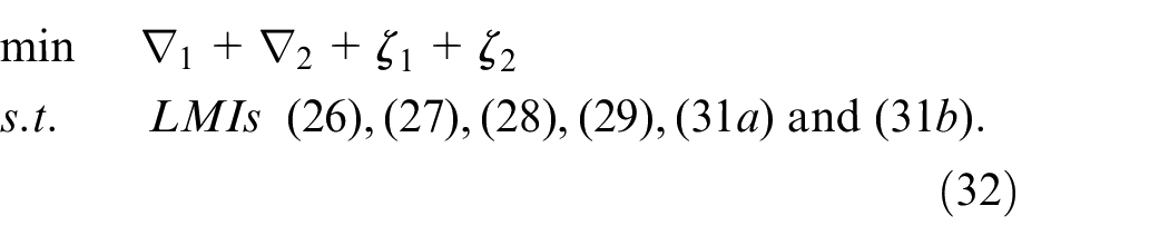
is feasible, Therefore, it can be inferred that the proposed controller outlined in (9) effectively stabilizes the nonlinear dynamic model (1) of the knee exoskeleton. Furthermore, the determination of the gain matrix

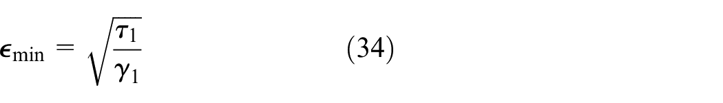
Additionally, the subsequent formula can be employed to calculate the minimum value of the parameter
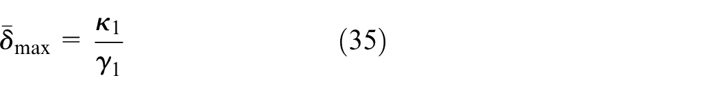
Moreover, the following expression may be used to determine the maximum value of parameter
Second approach for formulating LMI conditions
In this second design approach, we make the assumption that the function
As mentioned previously, the constraint applied to the proposed Lyapunov function (11) can be redefined by employing the expression (15). Furthermore, we will adhere to the same formulation (13) to derive certain LMI conditions for the feedback gain matrix
It is crucial to recall that
Since
where here
Moreover, recall that the function

with
Since
Hence, considering the above expressions, we can establish the following inequality:

where here
It is essential to highlight that for all values of
Let consider

Consequently, condition (38) is recast as follows:
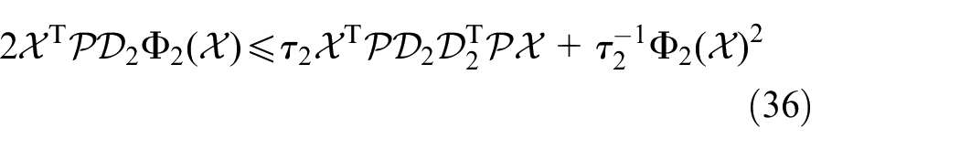
Moreover, taking into account that
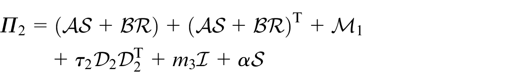
By substituting conditions (16), (38), and (20) into the resulting expression (13) and incorporating the constraint (14), we arrive at the following inequality:
Let consider
where
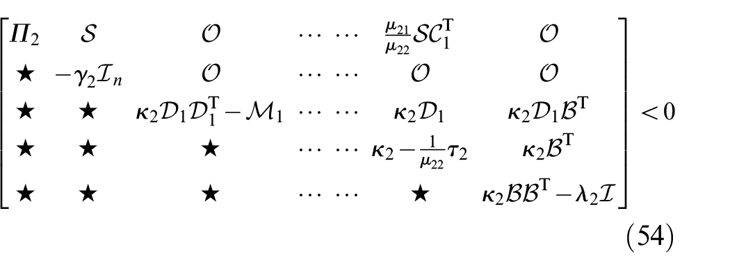
Utilizing the S-procedure and employing the expressions (40) and (15), we formulate the following stability condition:
where
Therefore, by multiplying the extended condition defined in (41) on the right and left sides by
where
with
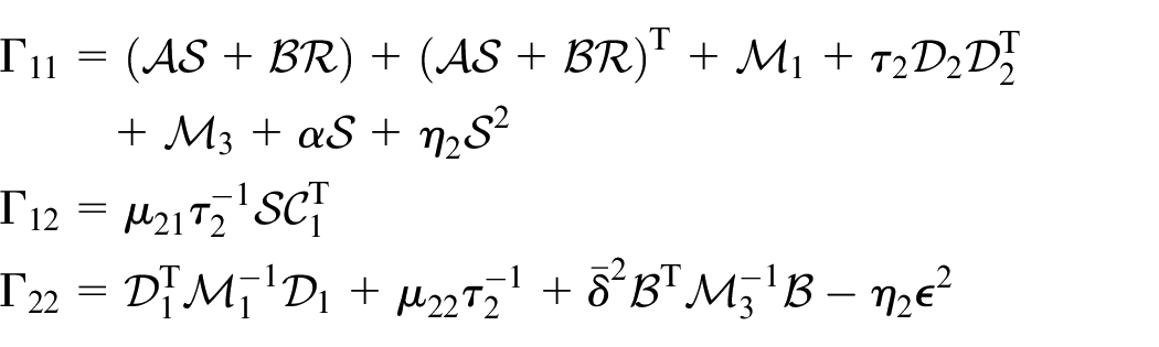
For the sake of simplicity, let define
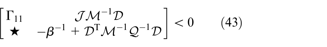
Applying the Schur complement lemma, the matrix inequality (43) can be reformulated as follows:

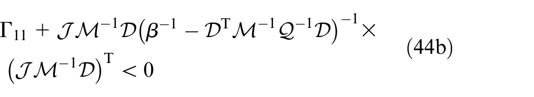
Using the matrix inversion lemma for the term on the left-hand side of the equation (44a), we obtain
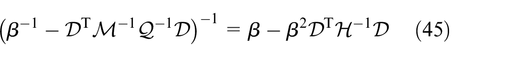
with

In accordance with equation (45), we can express inequality (44b) as equivalent to:
Let posing
Since the matrix
Utilizing the previously mentioned equations, we can simplify expression (48) as follows:

By employing (50) in (47), we derive:
Given that
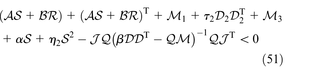
Furthermore, based on inequality (44a), and considering that
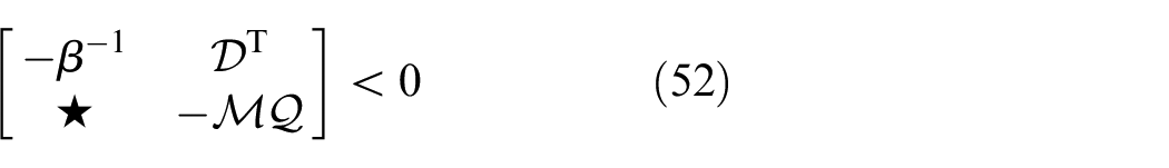
Therefore, by utilizing the Schur complement, we can establish that
with
Additionally, using the following new change of variables
where
It is worth emphasizing that

Thus, we can conclude that to minimize

By employing this expression and relying on the Schur complement lemma, we can derive the following LMI stability condition:
where
Additionally, it is important to observe that

Hence, to maximize

By utilizing this expression and applying the Schur complement lemma, we can formulate the following LMI stability condition:
where
As a result, we have derived the LMI stability conditions specified by (76), (57), and (60). These conditions are formulated in terms of the unknown variables
is feasible, then, it can be deduced that the proposed affine state-feedback controller defined in (9) stabilizes the nonlinear dynamics (1) of the knee exoskeleton robot. Additionally, the gain matrix
Moreover, the minimum value of the parameter
Furthermore, the maximum value of the parameter
Third design approach of the LMI condition
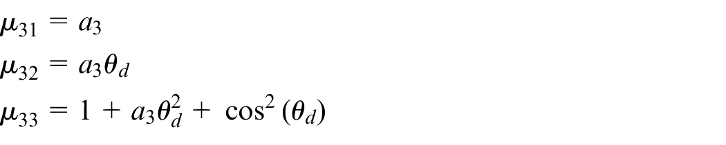
In this third approach, let’s proceed with the assumption that the function
As previously highlighted, the constraint applied to the candidate Lyapunov function (11) can be redefined by employing the expression (15). Additionally, we will retain the same formulation (13) to derive specific LMI conditions related to the feedback gain matrix
Furthermore, let’s reconsider the condition (16) and (20), along with the relation (17). It is straightforward to demonstrate the following inequalities:

with
Recall that

Hence, based on the evaluations above, we can establish the following inequality:

where the scalars
An important point to highlight is that, within the range of
Let us consider

Consequently, condition (36) is recast like so:
By substituting the constraints (16), (66), and (20) into the resulting expression (13) and by considering the constraint (14), we arrive at the following inequality:
As a result, we obtain
with
Utilizing the S-procedure and employing the expressions (67) and (15), we formulate the following stability condition:
where
Consequently, by multiplying the extended condition defined by (68) on both the right and left sides with
with
where the matrix
To simplify further, let’s define:
According to the Schur complement, we can reformulate the matrix inequality (70) as follows:
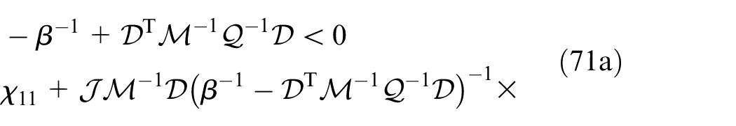
Using the matrix inversion lemma to the term on the left-hand side of expression (71a), we obtain the same expression (45).
Subsequently, based on equation (45), we can establish that inequality (71b) is equivalent to:
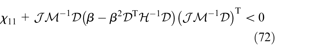
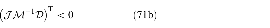
Posing
Given that
Then, by substituting (50) into (72), we obtain:
Given that
Therefore, when we consider

Hence, by employing this expression, we can represent inequality (51) as:
It is important to note that
Subsequently, building upon this expression, we can express equation (73) like so:
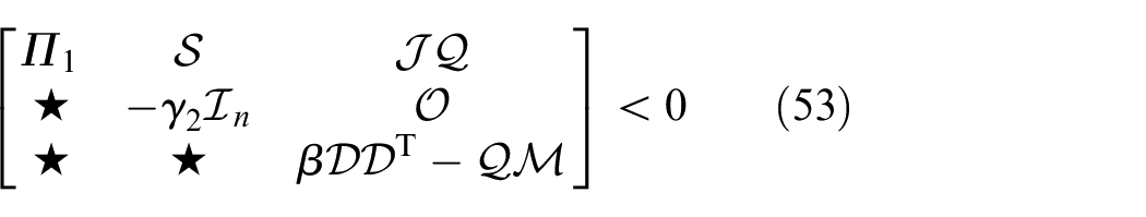
Therefore, using expression (52), by employing the Schur complement, we can establish that
where
Furthermore, let us take the following new variables’ change

with
it is essential to emphasize that
Moreover, it is crucial to recognize that
Hence, we have derived the LMI stability conditions presented in (76), (57), and (60). These conditions are formulated in relation to the unknown variables
is feasible. Accordingly, it can be asserted that the proposed controller, as outlined in (9), successfully achieves the stabilization of the nonlinear dynamics delineated in (1) of the knee exoskeleton rehabilitation robot. Additionally, the gain matrix
Results of simulations
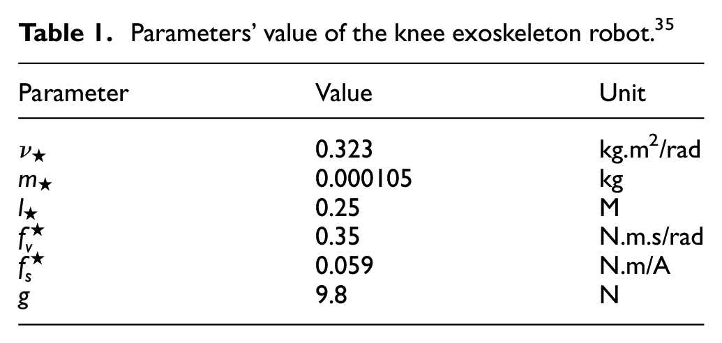
To ensure the stability of the actuated lower limb orthosis/exoskeleton at the knee joint level, we have developed three distinct LMI techniques. In the following section, we present the results of our comprehensive numerical analyses, meticulously demonstrating the effectiveness of each formulated LMI condition. To provide a comprehensive context, Table 1 compiles the values of various parameters crucial to the actuated knee exoskeleton robotic system, as described by equation (1).
Parameters’ value of the knee exoskeleton robot. 35
Continuing, we will vividly illustrate the control performance of the knee exoskeleton robotic system in response to the predefined target state
Additionally, we will introduce a distinctive external disturbance, denoted as

In this expression,
Results obtained using the first design approach
By applying the LMI stability condition established in Theorem 1 and by solving the associated LMI problem with a chosen parameter value of


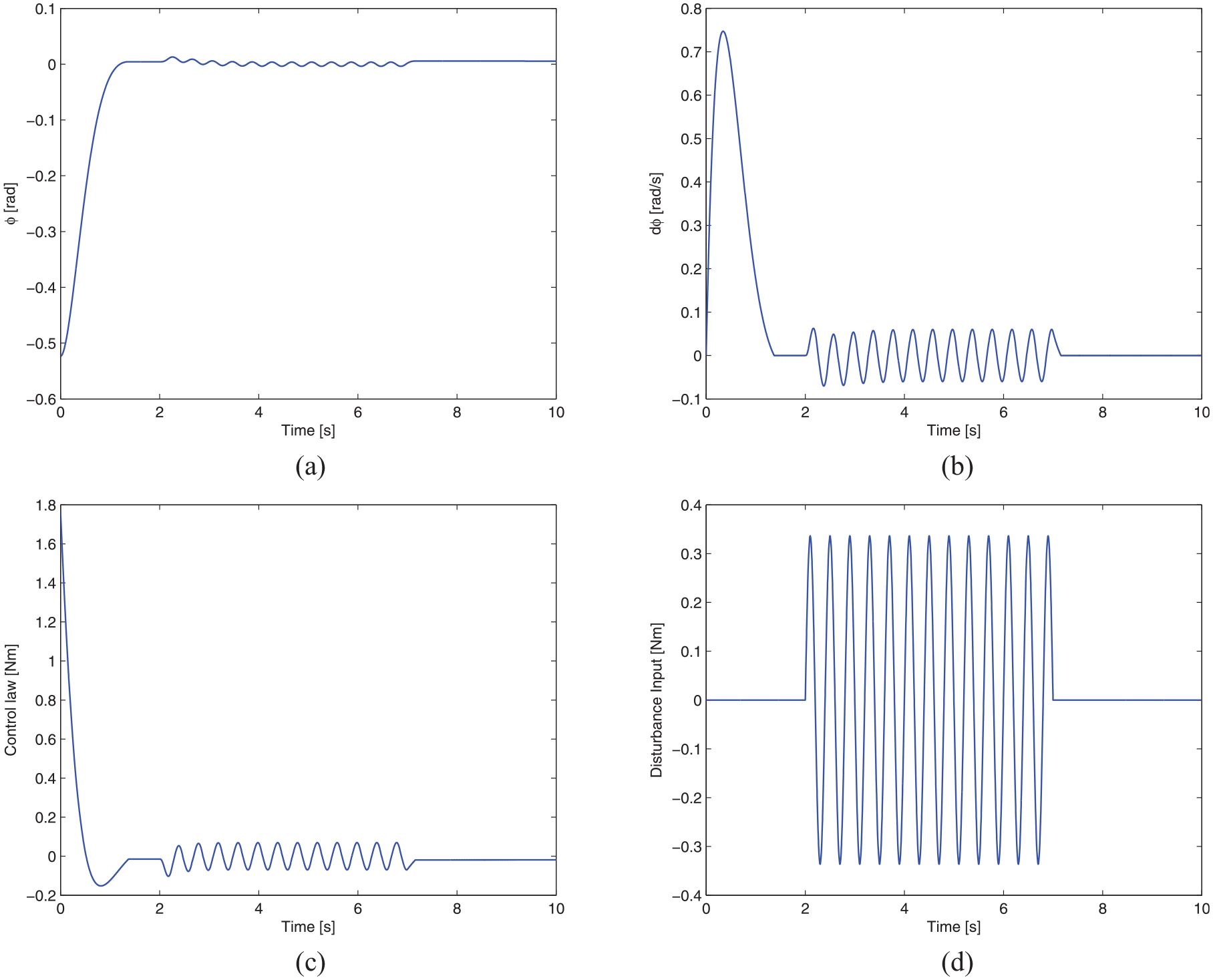
By incorporating the feedback gain (78a) into the state-feedback controller (9), we can examine the graphical outcomes as illustrated in Figure 2. The results clearly demonstrate the successful adjustment of the robot to the desired position
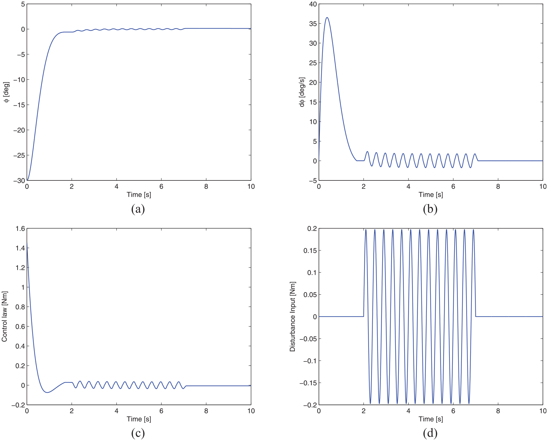
Graphical results of the regulated knee exoskeleton robotic system by adopting the first development approach: (a) presents the angular positions error
Results obtained using the second design approach
Implementing the LMI stability condition outlined in Theorem 2 and solving the associated LMI problem with


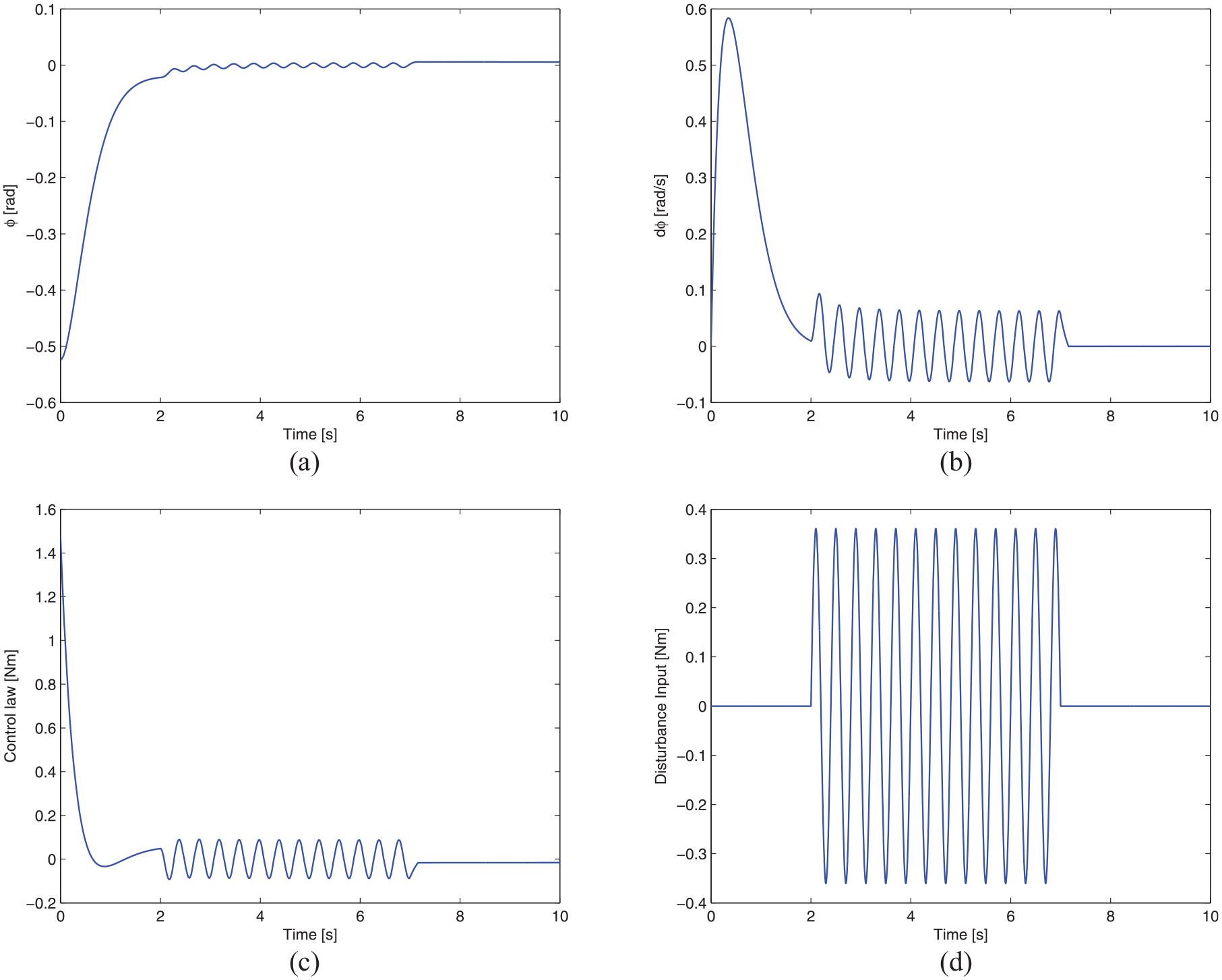
Implementing the feedback gain (79a) in the state-feedback controller (9), we can observe the graphical results illustrated in Figure 3. The robot accurately converges to the desired state
Graphical results of the regulated knee exoskeleton robotic system by adopting the second development approach: (a) presents the angular positions error
Results obtained using the third design approach
By solving the LMI problem associated with the LMI stability condition outlined in Theorem 3, specifically with


By incorporating the feedback gain (80a) into the adopted control law (9), we illustrate the graphical results shown in Figure 4. Consequently, the exoskeleton robot is successfully controlled to the intended position, specified as
Graphical results of the regulated knee exoskeleton robotic system by adopting the third development approach: (a) presents the angular positions error
Discussion
The proposed state-feedback control strategy plays a crucial role in effectively managing the intricate task of controlling the position of the actuated knee exoskeleton robotic system. This approach utilizes an extended feedback gain derived from three distinct methodologies, ensuring precise control over the robot’s motion. As the robot is guided toward the target state
Furthermore, the utilization of these three methodologies not only lead to a reduction in the angular position error
Figures 2(d), 3(d) and 4(d) offer a visual insight into the impact of an external disturbance, denoted as the applied load
Moreover, it is noteworthy that the time required for the knee exoskeleton robotic system to achieve stability varies among the three approaches. The first approach achieves stability in approximately 3 s, the second approach accomplishes this in under 2.7 s, and the third approach stabilizes the actuated knee exoskeleton in less than 2.6 s.
Significantly, the initial control effort
Comparison with the PID controller
In this part, the objective is to compare the performance of the adopted affine state-feedback controller to the PID controller. Such control law has the following expression:
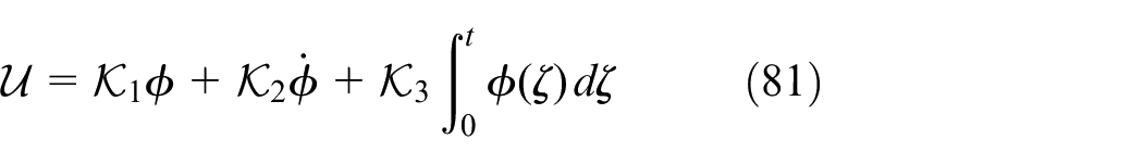
The goal is to find the values of the gains
By making some transformation of the nonlinear model (1) under the PID controller (81), it is possible to re-obtain the same nonlinear state-space representation (7) with same nonlinear functions

Using then the same three approaches for the design of the LMI conditions, we reconsider the LMI-based minimization problems presented in Theorems 1–3 for the computation of the gain
As previously, the desired position
Results using the first design approach for the PID controller
By adopting the previous fixed parameters


Compared to the results in (78), it is obvious that the maximum bound of the lumped disturbance (i.e.
Results using the second design approach for the PID controller
Let us consider the second design approach of the LMI conditions and then the LMI-based minimization problem in Theorem 2. Then, by considering the case of the PID controller, we obtain the following numerical results:


As found in the previous part, the value of
Results using the third design approach for the PID controller
Using the minimization problem under LMI constraints presented in Theorem 3 by considering in the present part the case of the PID controller, the following numerical results are then obtained:


As previously, compared to the results obtained via the affine state-feedback controller, the gain
In addition, for the PID controller, the value of
These obtained results reveal accordingly the superiority of the adopted affine state-feedback controller against the PID controller.
Conclusion and future directions
This study employed an affine state-feedback controller to effectively manage and stabilize the position of a knee exoskeleton robotic system, considering its nonlinear dynamics encompassing frictions, parameter uncertainties, and external disturbances. The control law was meticulously designed using the Lyapunov methodology, and we introduced three distinct methods to establish stability conditions for the feedback gain, leveraging specific technical lemmas. These conditions were subsequently translated into Linear Matrix Inequalities (LMIs). Through a comparative analysis, we evaluated the efficacy of each method, utilizing the LMI approach to derive gain conditions that guarantee the stability of the controlled knee exoskeleton. The simulation results presented in this study demonstrate that the designed LMI-based controller successfully achieves excellent stabilization of the knee exoskeleton system.
Looking ahead, several promising avenues for future research emerge. Firstly, while this study specifically focuses on one scenario of external disturbance, our goal is to evaluate the robustness of the implemented control law by subjecting it to various scenarios involving different external disturbances and uncertainties in the system’s parameters. Secondly, as we assumed in the present work that the external disturbances are bounded by a constant value, we plan to design an uncertainty and disturbance estimator for tracking control in fuzzy-switched systems. This additional feature will address potential challenges and contribute to the overall robustness of our proposed approach. Furthermore, we aim to explore the integration of a filtering mechanism that could potentially reduce the amplitude or duration of oscillations in the controlled system. Additionally, our future endeavors will concentrate on designing a robust static output feedback control law using the LMI approach. 38 Moreover, it’s worth noting that this work does not consider movement constraints related to the knee joint level. Hence, we are eager to incorporate movement constraints related to different lower limb articulations into the controller design. This integration aims to minimize control effort, reduce energy consumption, and ultimately enhance the overall efficiency and usability of the knee exoskeleton robotic system. In addition, the objective is to extend the LMI design approaches adopted in the present work and also the previous ideas to multi-degree-of-freedom knee-joint robotic systems.
To further advance the proposed approach, future developments could involve exploring adaptive control strategies for self-adjustment in dynamic conditions, investigating real-time implementation for practical validation, and conducting human-in-the-loop experiments to assess the system’s efficacy in rehabilitation scenarios. In terms of applications, the controller exhibits potential in rehabilitation robotics, assistive devices for mobility-impaired individuals, human-machine collaboration scenarios, and sports performance enhancement, showcasing its adaptability and robustness in diverse settings.
Footnotes
Declaration of conflicting interests
The author(s) declared no potential conflicts of interest with respect to the research, authorship, and/or publication of this article.
Funding
The author(s) received no financial support for the research, authorship, and/or publication of this article.
Data availability statement
Data sharing not applicable to this article as no datasets were generated or analyzed during the current study.