
Abstract
Energy ripples are among the common problems in renewable energies as a result of using less efficient strategies. In this work, a new technique is suggested to control a doubly-fed induction generator (DFIG) using the pulse width modulation (PWM). The new technique is based on the combination of neural networks and fractional-order control to minimize the reactive and active power ripples of the DFIG-based variable speed dual-rotor wind turbine system. The suggested fractional-order neural control (FONC) with the PWM is a simple, robust and a high-performance strategy. Simulation is performed using Matlab software to validate the effectiveness of the designed control of 1.5 MW DFIG and the obtained results are compared with the traditional direct power control (DPC) in different working conditions. In addition, the comparison between the suggested control and the DPC is performed in the cases of changing or not changing the device parameters in terms of ripple ratio, dynamic response, steady-state error, current quality, and overshoot of active and reactive power of the DFIG. As compared to the DPC, the proposed FONC technique improves the active and reactive power ripples by 65.71% and 84.74%, respectively. Also, improves the overshoot of the active and reactive power by 71.33% and 91.72%, respectively. The simulation results demonstrate the high performance and robustness of the FONC technique for the parametric variations of the DFIG-based variable speed dual-rotor wind turbine system compared to the DPC control.
Keywords
Introduction
Doubly-fed induction generator (DFIG) is one of the most widely used generators in renewable energy (RE). This generator converts the power gained from the wind by the turbines into electrical power. 1 To use DFIG in the field of wind turbines, electronic transformers must be used, as two transformers are used for this purpose. The use of a power electronics transformer is the key to connecting the system to the network via a DC-link capacitor. 2 The AC-DC-AC converter is modulated by a grid-connected grid side converter (GSC) and a DFIG-connected rotor side converter (RSC), where the purpose of using a GSC is to keep the DC link voltage constant regardless of the size and direction of the power rotor using a vector control. The role of using RSC is to optimize DFIG operation to provide maximum power output using vector control strategy.
Several reasons made DFIG sit on the top of the most popular electric generators because of the low cost, high durability, and ease of control of the rotational speed by feeding the rotor, which makes it operate in several different states and raises the efficiency of performance compared to several other types.1,2 To generate an electric current from DFIG, several control strategies are used for this purpose, whereby detailed modeling of DFIG, wind turbine, and inverter is necessary for the realization of the generation system. The control strategies used to control DFIG can be categorized into four main families as follows: (1) linear control, (2) nonlinear control, (3) intelligent control, and (4) hybrid control. These strategies are used in the field of control and differ from each other in terms of robustness, ease of implementation, degree of complexity, and the results presented to improve the response of the system under study.
Linear controls are strategies characterized by simplicity, quick dynamic response, and ease of implementation and application compared to other control strategies. 3 The most famous of these strategies are direct torque command (DTC), 4 direct power command (DPC), 5 and field-oriented command. 6 However, the DPC and DTC strategies have the same implementation principle, but uses specific switching tables (STs) to generate command pulses in the generator inverter.4,5 In this strategies, two hysteresis comparators (HCs) are used to control the characteristic amounts, where these two HCs are of different levels. But there are researchers who used two HCs of the same level, and this is by changing the ST, and in this case the control becomes another. The minimum level that can be used is two levels for each HCs, as the level of the used comparator is important in improving the characteristics of the two linear strategies. In addition, these strategies depend on estimating the characteristic values to calculate the error, so they need measuring devices with high accuracy. Unlike these strategies, the field-oriented control is completely different from the DTC and DPC techniques in terms of the implementation principle, and there are two types of this strategy: the direct technique 7 and the indirect technique. 8 This strategy relies on the use of the pulse width modulation (PWM) technique to command the generator inverter.6,7 Besides the PWM technique, a proportional-integral (PI) controller is used to command the characteristic magnitudes of DFIG. 9 Field-oriented control is less efficient than DTC and DPC in terms of power ripples, and quality of current, dynamic response. 10
In the field of control, the DPC technique is one of the most widely used strategies in the field of RE for the generation of electric power due to its multiple characteristics compared to some controls. In this strategy, the reactive and active power (Qs and Ps) is controlled using HCs, where two are used for the purpose of power control. To control the Ps, a three-level HC is used with its outputs being −1, 0, and 1. As for the Qs, a two-level HC is used with its outputs being 1 or 0. Besides HCs, ST to control the DFIG inverter is used. The role of the ST is to generate the necessary control pulses. This table has three entrances and three exits, where the entrances are represented in the error in the Ps, the error in the Qs, and sectors. The outputs are three different high frequency pulse signals. In addition, the DPC strategy relies on estimating both the Qs and Ps to calculate the error in the Qs and Ps, where the power estimate is linked to the system parameters, which creates several problems and defects, especially in the case of system parameters change, and this is undesirable.
Power quality is among the main problems in DPC technique, which limits its spread in the field of controlling electric generators, where the low quality of power (electric current) causes several problems in the network, which leads to imbalances in the operation of electrical machines. 11 Also, the low quality of energy leads to an increase in the periodic maintenance and thus a high industrial cost, which is undesirable. 12
To improve the efficiency of the wind power generation system using DFIG, several new strategies have been put forward, which can be summarized as follows: synergetic control, 13 backstepping control, 14 sliding mode command (SMC), 15 passivity command, 16 predictive command 17 fractional-order command (FOC), 18 intelligent control,19–21 high-order SMC,22,23 backstepping-SMC control, 24 synergetic-SMC control, 25 synergetic-super-twisting algorithm, 26 and terminal synergetic control. 27 These controllers are highly efficient in improving DPC performance in reducing DFIG power ripples to some extent. In these strategies mentioned above, a change was made in the DPC strategy, by eliminating two HCs and ST to minimize the Qs and Ps ripples. Also, by improving current quality, increasing system durability, and reducing dynamic response compared to the DPC. The use of these strategies, especially the non-linear strategy such as passivity control or backstepping control, creates many problems in DPC control, and this is not desirable. However, the disadvantage of using these controls is that it is related to the mathematical form of the DFIG, which makes it difficult to control and makes it more difficult to perform. Also, in the case of changing the parameters, it will lead to a deterioration of the dynamic response to these previously mentioned strategies, and thus a significant decrease in the Qs and Ps qualities. Therefore, it was necessary to think of a new command that is not related to the mathematical model of the DFIG, with an emphasis on durability, but also on ease and simplicity of operation. In addition, power ripple reduction is required when system parameters change.
The use of fractional-order control gives an advantage in terms of improving the characteristics of systems and overcoming the defects of control strategies. This control strategy is considered one of the most reliable mathematical solutions for controlling wind energy generation systems, as it is considered one of the least complex and most efficient nonlinear strategies in improving the systems’ characteristics, especially in the event of a malfunction in the machine. 28 In addition, the use of fractional-order control is not related to the mathematical model of the system, which allows the system not to be complicated and thus easy to implement. Also, excellent results are obtained in the event of a system malfunction as investigated in Benbouhenni et al. 29 In the latter, a PI controller based on fractional-order control was used to control the Qs and Ps of the DFIG-DRWT system, where the proposed control is characterized by simplicity, high robustness, and ease of adjusting the dynamic response. The use of PI based on fractional-order control led to a reduction in the active and reactive power ripples, especially in the case of system parameters changing in large proportions compared to the traditional control, which is a good thing. In Gasmi et al., 30 STA based on fractional-order control was used to overcome the defects of the FOC of the DFIG, whereby the traditional controllers were dispensed with and replaced by this proposed controller. The advantage of using this proposed controller is its high durability and simplicity, as there are few parameters, which makes it easy to adjust and control the dynamic response. This suggested technique has been applied to 1.5 kW DFIG using numerical simulations with comparison of results with FOC based on PI controllers. Another work on fractional calculus applications on wind turbines was done in Gasmi et al., 31 where Fractional-order proportional-integral super-twisting SMC was used as a suitable solution to control the Qs and Ps of DFIG. The latter is controlled by the FOC strategy, whereby four fractional-order proportional-integral super-twisting SMCs were used to compensate the PI controller with the use of PWM to generate the necessary pulses to control the inverter. This control is characterized by complexity, difficulty in execution, and the presence of many parameters, which makes it difficult to adjust the dynamic response of the system. However, the use of this proposed controller to improve the performance of FOC led to a decrease in power ripples, an improvement in current quality, and a decrease in steady-state error and overshoot, especially in the case of changes in system parameters compared to FOC.
Traditionally, intelligent strategies or what is known as artificial intelligence are among the most prominent controls at the present time, as they are no less important than nonlinear controls in controlling electrical machines. These smart strategies are many and varied, the most prominent of which are genetic algorithms (Gas), 32 fuzzy logic (FL), 33 neural networks (NNs), 34 gray wolf optimization, 35 particle swarm optimization (PsO), 36 ant-colony algorithm, 37 etc. These algorithms were proposed based on biological studies conducted on animals, and almost every algorithm is related to the behavior or way of living of animals, as in the case of gray wolf optimization, where this strategy was proposed based on the behavior of gray wolves in collective hunting.
These algorithms depend largely on the experience of the user, and they are algorithms that can be applied to all systems, as these algorithms are used to calculate the parameters of the system such as GA technique. The use of these smart algorithms leads to a significant improvement in the efficiency of the systems. In Iqbal et al., 38 the PSO algorithm is used to calculate the PI controller parameters of a wind turbine control system based on DFIG to improve the current quality. Simulation was used to implement this intelligent control with a comparison of the results with the traditional control that depends on the PI, where the results showed that the use of the PSO algorithm leads to a significant improvement in the characteristics of the system compared to the DPC.
FL strategy is the most prominent smart strategy in the field of controlling electrical machines, as it was proposed by the scientist Zadeh in 1965. 39 This strategy depends on the use of logic that is different from the ordinary logic that depends on right and wrong. In FL, functions called logical functions and logical rules are used, where the larger the logical rules, the greater the efficiency of FL in improving the system’s properties. 20 But there is a negative to this strategy lies in making the system slow the greater the number of rules used and this thing is undesirable. FL technique has been used in many different fields, as it has been used in the field of controlling asynchronous motors, 40 controlling multi-level inverters,41,42 and in the field of renewable energies.43,44
The use of FL strategy in the field of renewable energies leads to a significant improvement in the quality of the current, a decrease in the THD value of the current, an increase in the durability with a reduction in the active and reactive power ripples, especially in the event of a fault in the system. 45 One of the disadvantages that FL technique can create is in the case of a large number of FL controllers in a system, as it leads to difficulty in adjusting the response due to the large number of parameters. As it is known, in one FL controller there are three parameters that must be well defined in order to get an excellent response, and therefore the greater the number of FL controllers, the greater the number of parameters, and this is undesirable and leads to the complexity of the system. 46 In Heydari et al., 47 the GA technique was used to calculate fuzzy control parameters in order to overcome the drawbacks of the DPC of DFIG. The use of GA led to a significant improvement in the performance of the FL, and this is noted through the obtained results compared to the DPC, where the use of FL-GA technique in the DPC led to the reduction of the Qs and Ps ripples and the reduction of the THD value of current coming out of the stator of the generator. In Farida et al., 48 FL technique and high-order SMC are combined to create a robust and highly efficient controller to overcome the problem and drawbacks of a DFIG-based wind power generation system. The use of this combination of two different controllers greatly improves the robustness of the system while reducing the chatter phenomenon present in the SMC which is desirable.
Another smart strategy represented by NN techniques relies heavily on experience, where simplicity and robustness are among the most prominent features of this smart strategy. 49 The basis of the functioning of NN techniques is to simulate the functioning of the human brain by applying a network of linked inputs and outputs. This strategy depends on learning using learning algorithms, where Levenberg-Marquardt (LM) technique is one of the most popular and most used learning algorithms. 50 A NN has at least three layers (one input, one output, and one or more hidden layers). As is known, no constraint is imposed on the number of nodes allocated in the hidden layer, and their number is optimally chosen depending on the application. Thus, compared to conventional controllers, a NN-based controller can become a more efficient and reliable alternative for active and reactive power control in the wind system. Compared to other smart strategies, NN techniques are multiple, and each network has advantages and disadvantages that distinguish it from other networks. Among the most prominent of these networks, we mention newff, which means a feed-forward backpropagation network and newcf means trainable cascade-forward backpropagation network. NN techniques have been used in several different fields because of their ease of application and their ability to improve the dynamic response of systems compared to traditional controls.49,50 In Gu et al., 51 a Hopfield fuzzy NN technique is proposed in a DFIG and superconducting magnetic energy storage module to make the corresponding frequency control approach more adaptive. The simulation results showed the superiority and high efficiency of the Hopfield fuzzy NN in improving the dynamic performance of the studied system compared to the traditional control. In Behara and Saha, 52 artificial neural predictive control was used to improve the quality of energy generated by DFIG in different working conditions. This strategy aims to enhance the productivity of wind turbines, achieve a stable network connection, and ensure that they operate as efficiently as possible. Artificial neural predictive control was implemented using Matlab software, and the results were compared with existing strategies in terms of output power quality and torque ripples. The results of the simulation demonstrated the quality of current and energy in the case of using artificial neural predictive control compared to other controls. Several advantages come with using NN technique, such as better grid stability, improved energy efficiency, and reduced operational costs. In Chojaa et al., 53 a new control based on the use of the NN to control the DFIG powers present in the wind system. Two neural controllers were used to control the capacities, and PWM was used to produce the necessary pulses to control the DFIG inverter. The advantage of the proposed control is simplicity, robustness, and ease of implementation compared to several strategies such as backstepping control. This control was implemented by Dspace 1104 card on a generator with a capacity of 1.5 kW in different working conditions such as variable wind speed, where the experimental results were compared with both DPC and backstepping control. The work 54 proposes an adaptive neural fuzzy control for maximum power point tracking (MPPT) for wind power conversion systems connected to a DFIG. The use of adaptive fuzzy neural control aims to extract maximum power from the wind by tracking the maximum power peak regardless of wind speed. Moreover, the proposed MPPT controller implements an adaptive fuzzy-NN control approach with back propagation algorithm, where the rotor speed acts as the input to the controller and the torque reference as the output to the controller, which increases the input of the rotor side transducer speed control loop to control the actual speed of the rotor from By adjusting the operating ratio of the RSC. The role of the NNs is to train the fuzzy input membership according to the input and change the initial membership functions. A Matlab environment is used to implement the proposed control of a 2 MW wind turbine under different wind speed conditions and compare it with the performance of a DPC. The results showed that the wind energy generation system operates at its full optimal power for the wide range in the case of using the proposed smart control unit compared to the traditional control in the case of variable wind speed. The work done in Benbouhenni and Bizon 55 aims to increase the Qs and Ps extracted from variable speed DRWT system-based DFIG by optimizing their operation using advanced direct vector control. In this work, direct vector control based on NN techniques are used, where all the traditional controls 55 are replaced by smart ones in order to control the active and reactive power. In addition, fuzzy PWM technique is used to generate the pulses needed to control the generator inverter. Matlab/Simulink simulation software was used to prove the effectiveness of the proposed intelligent control using 1.5 MW DRWT, as the results showed good performance in terms of response time, stability and accuracy in following references under conditions of variable wind speed. In addition, the smart strategy proposed in Benbouhenni and Bizon 55 gave a good value of current total harmonic distortion (THD) (0.13%) compared to the traditional control and other strategies mentioned in the literature. Also, the proposed intelligent control minimized the response time to active power by approximately 64.4% and 90.11% compared with neural second-order SMC and DPC, respectively. As for the reactive power, the ratio was about 5.55% and 50%, compared with neural second-order SMC and DPC, respectively. In Chien et al., 56 a complementary frequency controller based on the NN technique is designed for a wind farm, where the gain of the optimal controller giving the highest nadir frequency or the lowest peak frequency is a complex nonlinear function of load perturbation and system variables, thus it is not easy to use analytical methods to derive the optimal gain. The author has used the NN technique which uses load turbulence, wind penetration and wind speed as the input and desired console gain when suggesting the output, where once trained through an appropriate set of training patterns the NN technique can be used to achieve the desired gain in a very efficient manner and this is in the absence of an operating condition in the training group. Another application of the NN technique is in the field of wind power generation systems, particularly in controlling the rotational speed of a turbine. The work done in Ghefiri et al. 57 aims to test and implement a new NN technique to provide a suitable reference for the rotational speed and blade inclination angle of a wind turbine. The NN strategy supervisor limits the power and switches the system appropriately in the variable speed modes. Rotational speed control is applied to the rotary bypass inverter by following MPPT generated by NN technique block in order to recover maximum power from tidal current, NN technique adjusts the rotational speed and blade inclination angle to protect the turbine from strong tidal currents. Accordingly, the simulation results show that the applied NN technique achieves smooth power generation under different working conditions compared to the traditional PI-based control. Also, the use of NN technique leads to real-time frequency control. The simulation results performed on a power system in Taiwan revealed that the NN technique can yield better frequency response than the fixed gain controller. The work done in Sun et al. 58 presents a scientific study of a short-term wind turbine outage model based on data collected from a wind farm supervisory control system and data acquisition using the NN technique. In this work, the NN technique was used to generate prediction models for wind turbine state parameters that depend on different environmental conditions such as temperature change and wind speed change profile. The distributions of prediction errors were studied and used to calculate the operating probabilities of protection relays that resulted from exceeding the threshold of environmentally sensitive parameters, where the union probability method is used to integrate the operating probabilities of each protection relay to predict the short-term outage probability of wind turbines. The results obtained from the proposed method using real 1.5 MW with DFIGs showed its superiority in predicting the wind turbine outage probability over the conventional strategies, and this is a good thing that proves the high performance of the NN technique. Moreover, another application that has demonstrated the efficiency of the NN technique is the multi-level inverter control in the works.59–62 In these works, the NN technique was used to generate the necessary control pulses to operate the inverter instead of using modulation techniques such as SVM, where the use of this smart technique led to a significant improvement in the performance of the inverter and to a decrease in the THD value of the current, and this was confirmed by the experimental work carried out in Boudjema et al. 62 In Benbouhenni,63,64 the problem of chatter found in nonlinear strategies such as SMC and High-order SMC is addressed, where the NN technique is proposed as a suitable solution due to its accuracy and its irrelevance to the mathematical model of the system. In this work, the Sign(u) function has been replaced by the NN algorithm with one inner layer. Through the results obtained, it is noted that the phenomenon of chatter was significantly reduced compared to the traditional controls of SMC and third-order SMC. Along with the noise reduction, active and reactive power ripples are also reduced by the high percentage of the DFIG-based DRWT system. Also, it is noted, an improvement in the quality of the current compared to the traditional controls and this appears through the reduction rate of high THD, which indicates the extent of the efficiency of neural networks in improving the characteristics of classical controls and systems in general. Several scientific works have proposed the NN strategy to overcome the drawbacks and problems of the DPC of DFIG.65–68 In this work the ST and two HCs were compensated by the NN technique keeping both Qs and Ps to calculate the error in the capacities. These smart strategies for DPC are characterized by their simplicity, low cost, and ease of implementation compared to many other controls such as the backstepping control. The use of a capacity estimate creates several problems in the event of a malfunction in the machine, such as an increase in the value of the current and torque ripples, a decrease in the quality of the current, and an increase in the overshoot value of the Qs and Ps, and this is undesirable.
This work deals with an application of neural networks with fractional-order control in order to control the capabilities of a DFIG-based DRWT system, where this work aims to reduce Qs and Ps ripples, improve the current quality by reducing the THD value, improve the values of time response and overshoot of power, and increase the durability of the wind power compared to the DPC. Also, the proposed control differs from the controls mentioned above, which is characterized by high efficiency with no connection to the variables of the studied system, which gives better results in the event of a defect in the system.
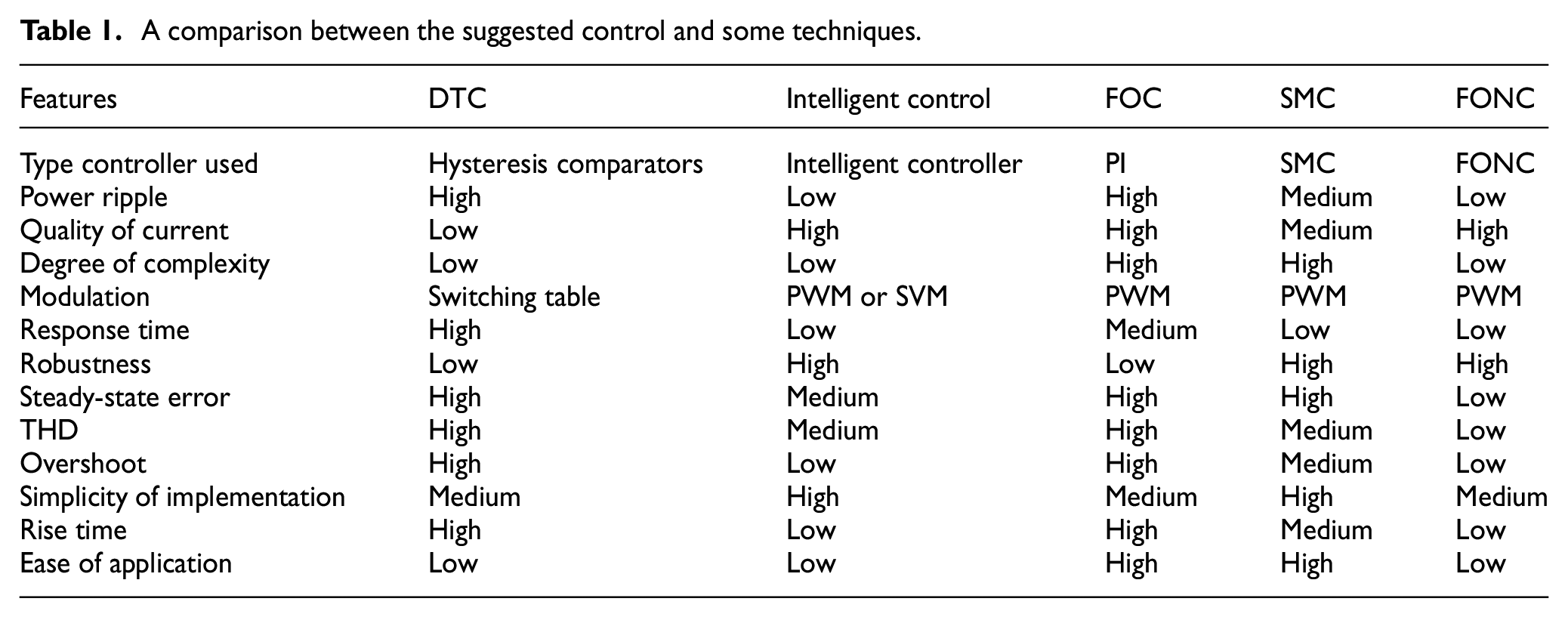
The proposed control in this work is fractional-order neural control (FONC), where this control is a combination of two different strategies in principle and characteristics. This proposed strategy is the main contribution of this paper. The FONC strategy implemented in this paper differs from several published scientific works such as Boudjema et al., 62 Benbouhenni64,66,68 where it was addressed for the first time in this work. This proposed FONC control is used to improve the characteristics of the DFIG-based DRWT system, where two FONC controllers are used to control the active and reactive powers. In addition, the PWM strategy is used to generate the necessary pulses to control a two-level inverter, which makes the proposed control one of the simplest and easiest existing strategies. It is necessary to give the similarities and differences between the control proposed in this paper and some existing strategies such as DPC, SMC, FOC and backstepping. These similarities and differences were given through this work carried out, the results obtained and the work mentioned above, where a comparison is recorded in Table 1. This comparison proves that the proposed control has some similarities with several strategies such as DPC in terms of the use of capacity estimation and controlled references. Also, there are differences with other strategies such as backstepping control, as the proposed control is completely different. So, the proposed control has characteristics that can make it among the best suitable solutions for controlling electrical machines in the future.
A comparison between the suggested control and some techniques.
The proposed control is validated using Matlab software on 1.5 MW DFIG in different working conditions, where the proposed control is compared with the behavior of DPC in terms of response time, ripple reduction ratios, Qs/Ps, overshoot,…etc. The results shown in the results and analysis section are the extent to which the proposed control can significantly improve the system characteristics, especially in the occurrence of malfunctions in the machine compared to DPC. The following points highlight the study’s contributions:
The simulation results are compared to those obtained using traditional DPC technique and with some existing work.
Minimizing energy ripples.
The performance of the designed control is evaluated in terms of response time, overshoot, SSE, THD value of current, robustness, and Qs/Ps ripples.
The fractional-order control is combined with neural networks algorithms to regulate the reactive and active power of the DFIG.
Increasing the robustness of the energy generation system
Reduction of overshoot and steady-state error values.
Decreasing the THD value of the current.
The rest of this work is organized as follows: In Chapter 2, the mathematical form of the proposed FONC technique, advantages, and disadvantages, are given. In Chapter 3, the modeling and control of the DFIG-DRWT are given. In Chapter 4, the simulation results are given. Finally, the conclusions are outlined in Chapter 5.
Fractional-order neural control
In this section, the FONC technique proposed for DFIG is presented, the operating principle, mathematical form and the arguments for and against the control suggested in this work being detailed. The advantage of this control is that it is easy to implement and simple, as it is a combination of two different controls in principle and idea. Proposed FONC technique depends on the accuracy and robustness that characterize NNs algorithm with the use of FOC to increase the robustness of control even more. Equation (1) expresses the mathematical form of the proposed control.

where, u(t) is the output of the proposed controller, ξ is the gain representing the FOC technique.
Equation (1) is the mathematical form of the proposed FONC technique in this work, where it is noted that the designed technique is not related to the system parameters, which makes it more robust in the case of changing the DFIG parameters. Figure 1 represents the proposed control, where there is only one input and one output. The input is the error in the amount to be controlled. Through this form, the suggested control is very simple and the response can be easily set because there is only one parameter (ξ > 0) by which the dynamic response is controlled. In addition, this control is inexpensive and easy to maintain. The other advantage of this suggested technique is that it is possible to change the type of control according to the value of ξ only, where if ξ = 1, then the FONC technique becomes NNs control only. In the case of ξ ≠ 1, the control achieved becomes the proposed technique. The condition that must be taken is that this factor of ξ does not take a value of 0.
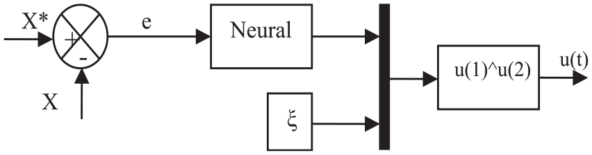
FONC technique.
NN algorithms are several different algorithms that have a high ability to improve the efficiency of systems, where accuracy is one of the most prominent features of these algorithms compared to some other strategies.69,70 The use of NNs algorithms leads to a significant improvement in dynamic response. 71
This suggested controller is used to improve the DPC of DFIG, whereby the HCs is dispensed with and replaced with the suggested technique. The suggested technique based on the use of the FONC is detailed in the next part of the paper.
Designed FONC strategy
As is known, the NN technique can effectively approximate and interpolate multivariate data that may require large databases, as this strategy is well accepted for nonlinear statistical fitting applications. The wind turbine system is a variable wind speed nonlinear system combined with DFIG integration and network connection through a cascade transducer makes this system more complex. In this context, the single-layer NN strategy combined with fractional-order control was presented as a promising solution to deal with system nonlinearity from variable wind speed to the grid. The proposed strategy (FONC technique) aims to control capacities. On the other hand, the proposed control outputs are the rotor voltage references, where these reference voltage values are used to calculate the inverter feed voltage. However, the PWM is used as a suitable solution in order to simplify the system, reduce the total cost, and generate the necessary pulses to operate the inverter. The latter has two levels to facilitate work.
The suggested FONC technique in this section is different from the traditional control (DPC), whereby two HCs and ST are dispensed with to improve the characteristics of the power generation system that depends on the use of DRWT, where the two-level PWM inverter is used instead of using the ST to generate the control pulses of the RSC of the DFIG. Also, the proposed FONC technique was used in place of the HC to control the Qs and Ps of DFIG. Figure 2 represents the suggested control in this work, where simplicity, robustness, and ease of implementation are among the most prominent features of this designed command. In addition to these advantages, there are other advantages such as fast dynamic response, reduced power ripples, and improved current quality compared to the DPC. All this will be demonstrated and proven in the next section.
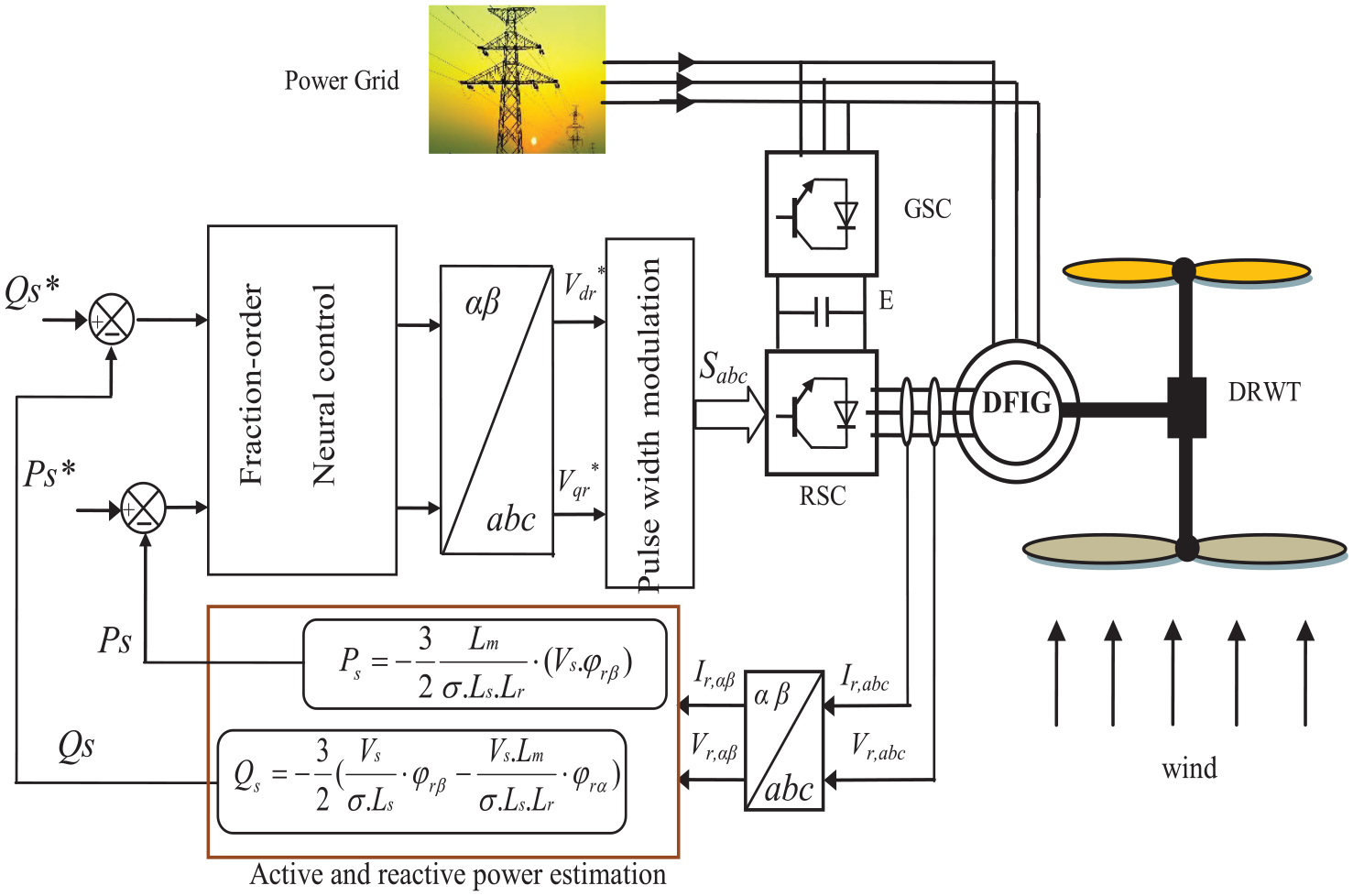
FONC technique of DFIG-DRWT system.
The FONC strategy of the electrical part of the system is devoted to the DFIG focusing on the Qs and Ps command. This command approach is realized by the energy electronics converters such as the RSC and the GSC. The RSC aims to maintain the rotational speed of the DFIG at an optimal value and minimizes the core losses while the GSC is used to maintain the voltage of the DC-link and commands the output Qs.
In FONC strategy, power estimation is used, where the estimated values are used to calculate the error in the Qs and Ps. In addition, Qs and Ps-error are two inputs of the two proposed FONC techniques of the DFIG-DRWT system. Among the conditions that must be taken to obtain better results is the selection of voltage and tension measuring devices with high performance to obtain real measured values.
The reference value of the Ps is calculated using the MPPT strategy, which makes the power generated from the generation system highly dependent on the wind speed (WS). As for the reference value of the Qs, it is fixed at the value of 0 VAR, as its value is not related to the WS.
The proposed control depends on the use of two FONC techniques to regulate the powers of the DFIG-DRWT system. Besides the FONC controller, the SVM strategy can be used to command the inverter instead of using the PWM strategy for control. However, using the SVM increases system complexity and total cost, which is not desirable. So this strategy aims to calculate the reference values of the rotor voltage to use it in controlling the inverter. In addition, the estimation of the DFIG power is necessary for this proposed strategy to determine the error in the DFIG power. Accordingly, the reference rotor voltage values are calculated according to equation (2).
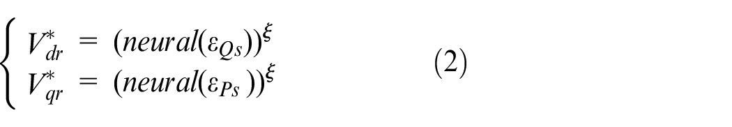
Figure 3 represents the suggested FONC to regulate the Ps and Qs power of the DFIG-DRWT system.
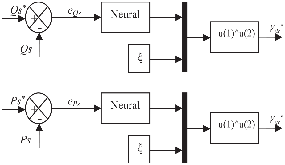
FONC of Ps and Qs controllers.
The suggested technique differs from several strategies in terms of complexity, simplicity, and principle. However, this proposed FONC strategy has the same equations used in estimating both reactive and active power in both DTC and DPC. Accordingly, the Ps and Qs is estimated according to the following equations 65,66:
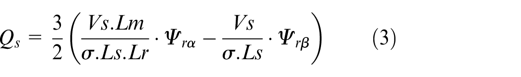
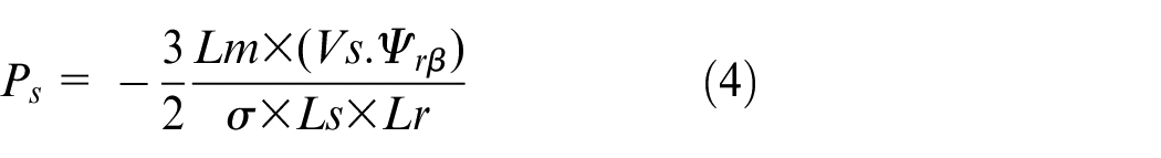
The error in the capacities is expressed by equation (5).
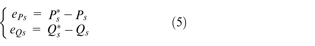
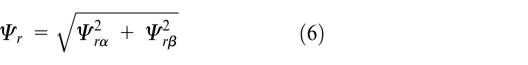
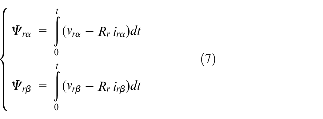
To estimate the powers first, the flux value must be calculated according to the equation (6), where the values of direct and quadrature rotor flux (Ψrβ and Ψrα) are calculated first.
A cascade-forward backpropagation network is used to achieve the proposed technique of DFIG power control, as Figure 4 shows the structure of the NN technique used in this work. The acronym newcf is an acronym that expresses the NN technique in Matlab software, as it is used to achieve it. Cascade-forward networks consist of several layers using the DOTPROD weight function, specific transfer functions, and the NETSUM net input function. 72
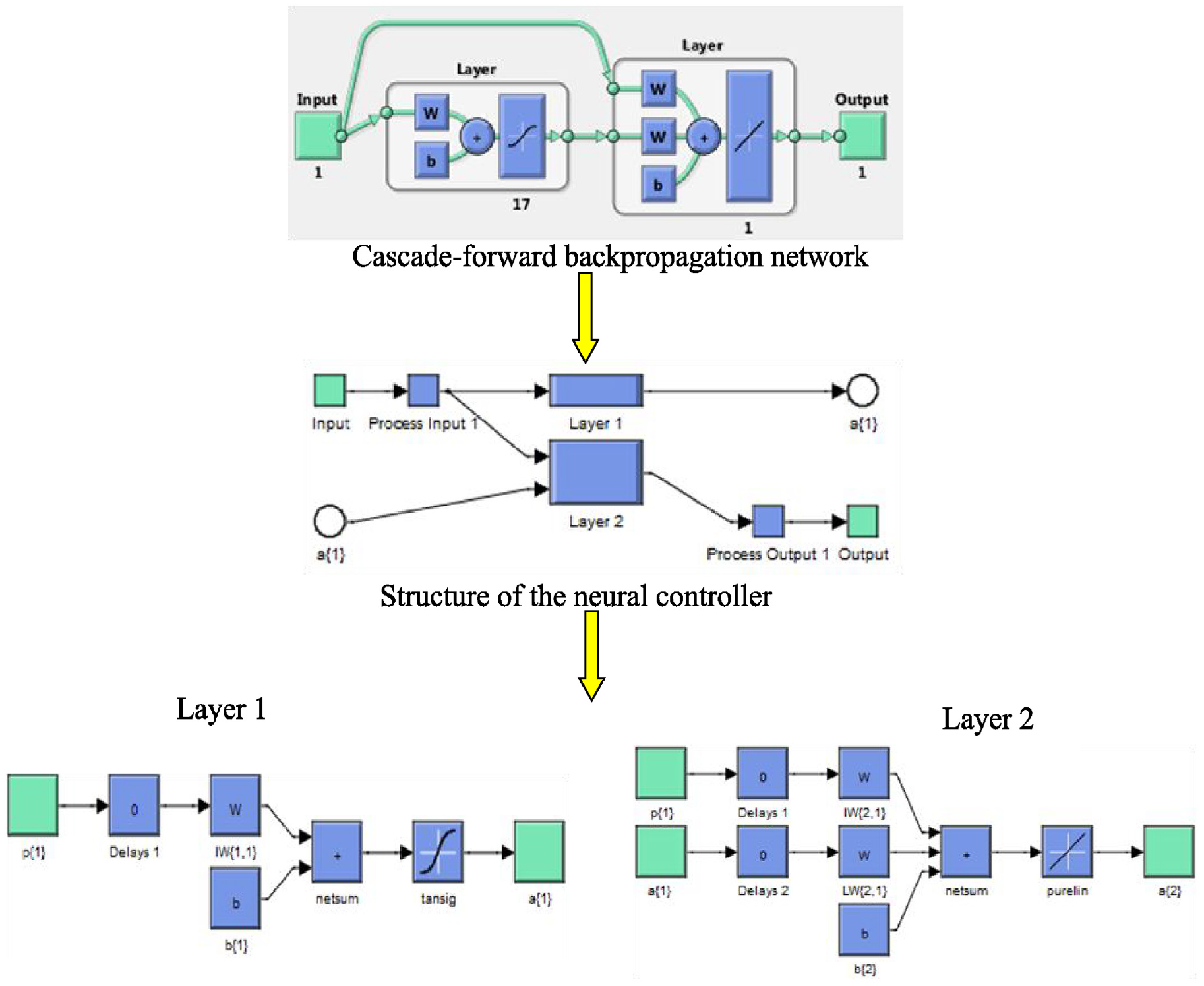
Cascade-forward backpropagation network.
For the first layer, it has weights coming from the input. Each subsequent layer has weights coming from the input and all previous layers, where all layers have biases. The last layer is the output of the network. The weights and biases of each layer are initialized using INITNW. Adaptation to TRAINS that updates the weights with the given learning function. The training takes place with the specific training function. Performance is measured according to the specific performance function. This controller has one input and one output, as 17 neurons were used in the first layer and only 1 neuron in the second layer.
To implement NNs, the following properties were used: 1000 for epochs, 0.02 for net.trainParam.lr, 0.8 for net.trainParam.mu, 1 for net.trainParam.showWindow, 0 for net.trainParam.goal, and the functions used are tansig, purelin, and trainlm. Figure 5 shows the best training performance of the FONC-Ps controller, where the best training is 62,987.0855 at epoch 147. Figure 6 represents Target in the Ps state, where the output is given according to the following statement: output = 1 × Target ± 0.21. Also, from Figure 6 it is noted that Training is R = 0.99977 and this value is excellent indicating the high efficiency of the used controller. Figure 7 represents the properties of the NN technique used to implement the Ps controller, where gradient, mu, and Val fail are given. The gradient value is 13,300.2416 at epoch 148. At epoch 148, the gradient value is 13,300.2416. Mu takes the value 80,000,000,000 and validation checks is 0.
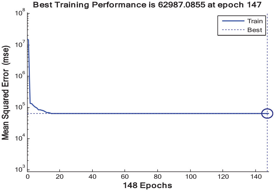
Best training performance of the active power FONC controller.
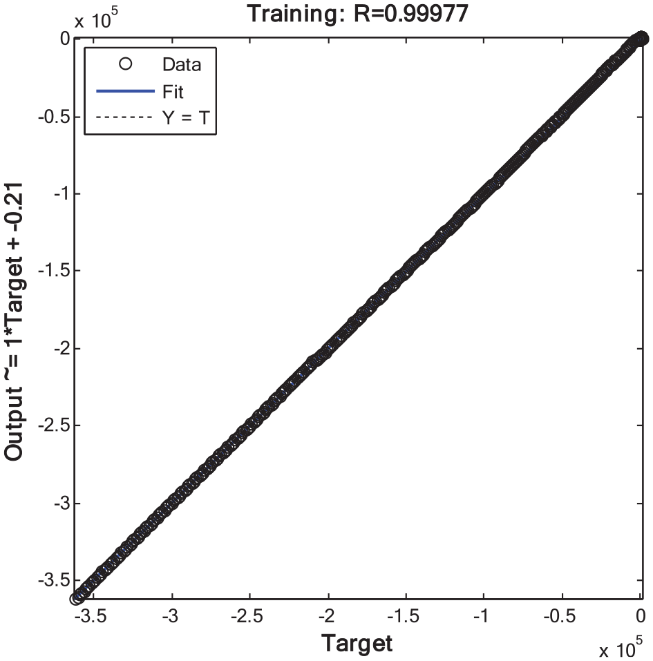
Target of active power FONC controller.
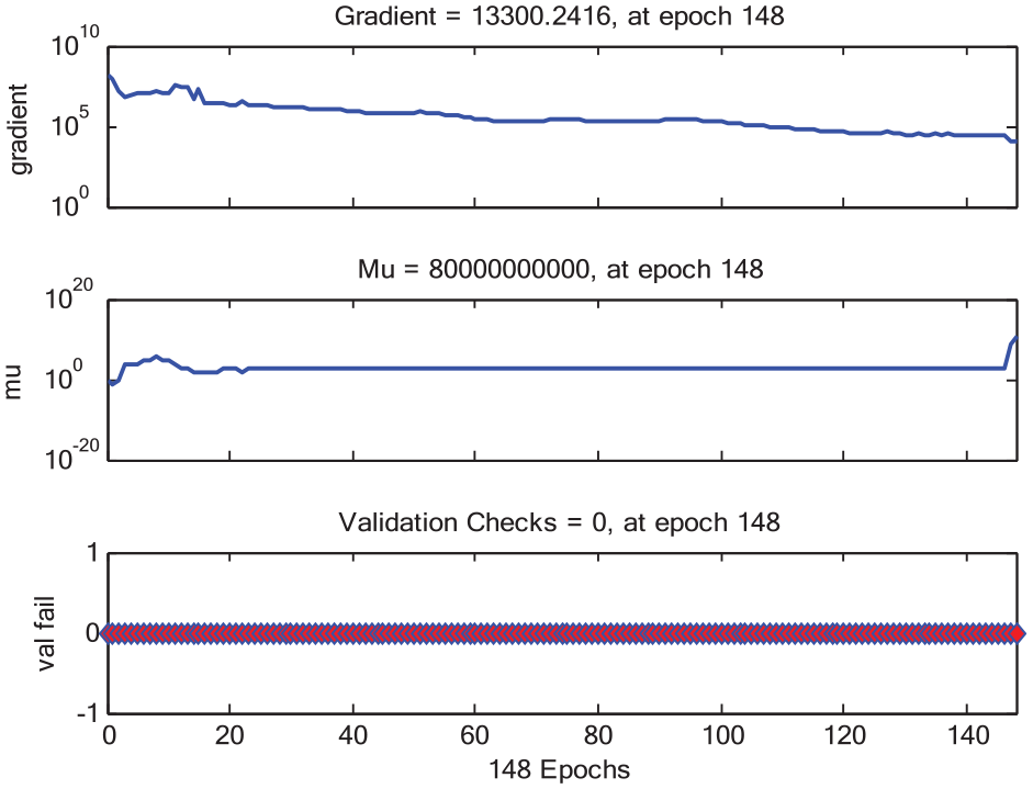
Characteristics of active power FONC controller.
In Table 2, a comparative study was conducted between the two strategies, DPC and FONC, as this comparison was made based on the results obtained from the results section. From Table 2, the proposed strategy has a high potential and efficiency to improve the properties of the systems. Moreover, the proposed control has the same characteristics as the classical control, such as simplicity and ease of implementation. Also, they use the same estimation equations for both Ps and Qs.
Comparison of the two strategies DPC and FONC.
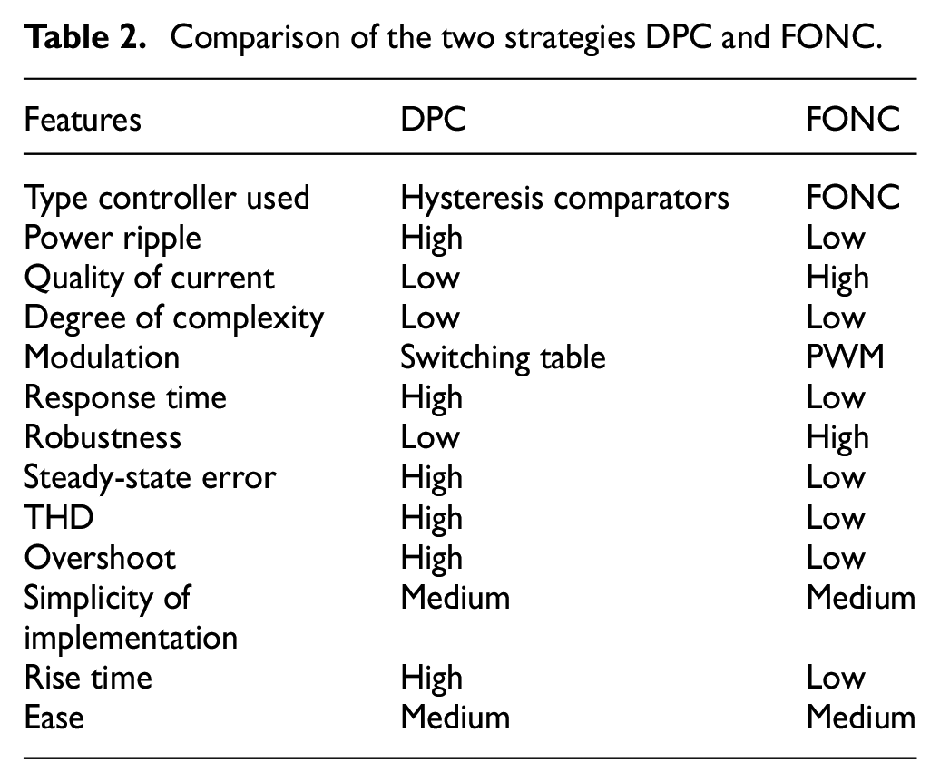
In the next part, the behavior of the suggested technique and the characteristics that were listed in Table 2 are verified. Accordingly, the behavior of the suggested technique is verified in the case of variable WS, taking into account the quality of the generated energy and the THD value of the current. In addition, a DRWT is used to convert wind power into mechanical power to rotate the generator and thus obtain energy.
Results
In this part, simulation results are given using Matlab software for the proposed FONC strategy of DFIG-DRWT system, where the DFIG parameters are as follows: p = 2, 380/696 V, J = 1000 kg/m2, 50 Hz, Psn = 1.5 MW, Lm = 0.0135 H, Ls = 0.0137 H, Rs = 0.012 Ω, Lr = 0.0136 H, Rr = 0.021 Ω, and fr = 0.0024 N/m/s.73,74
The obtained results are compared with the DPC in terms of reference tracking, overshoot, robustness, SSE, and response time. Therefore, two tests are suggested to investigate the behavior of the FONC strategy.
First test
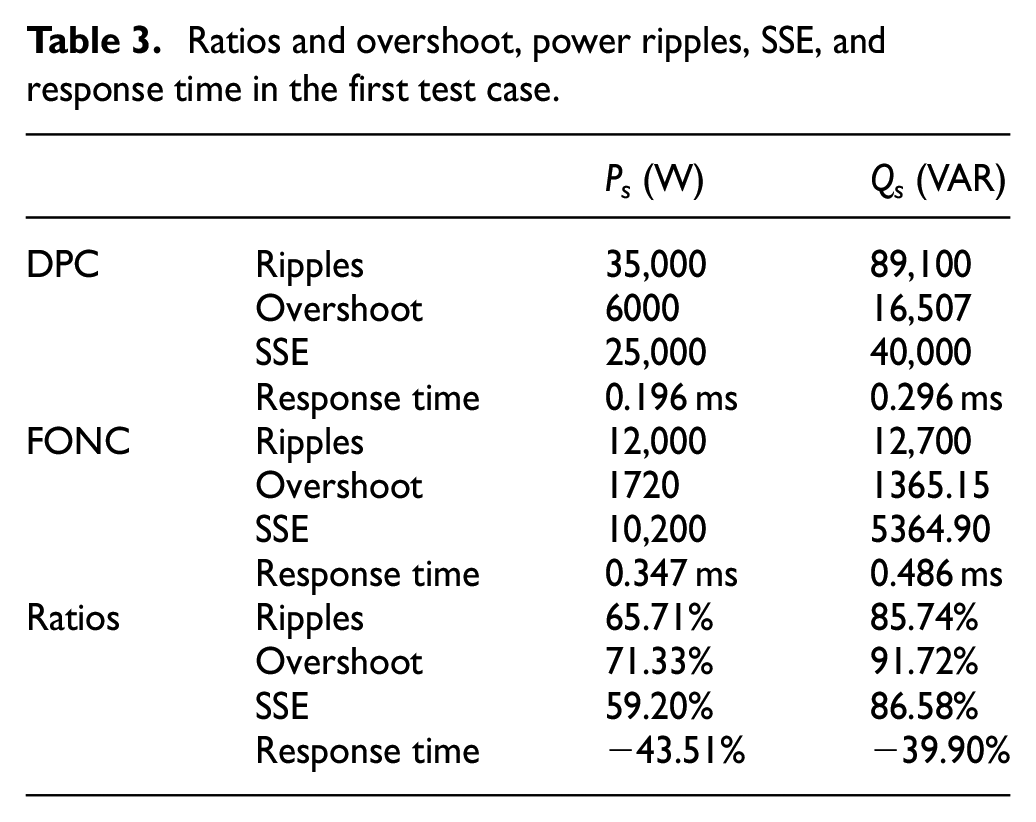
In this test, the behavior of the FONC is studied in terms of tracking references, where the results are represented in Table 3 and Figures 9–11. The WS profile used in this test is represented in Figure 8. Figure 9 represents the THD values of the current for the techniques used in this work. The THD value of the current in the case of the FONC strategy was 0.45% and for the conventional DPC, the value was 1.45%. Therefore, the ratio of THD reduction was estimated at 68.96% compared to the DPC technique. This percentages (68.96%) confirms that the current shape, current quality, and ripples are much better in the case of the proposed control compared to the DPC and this is highly desirable and proves every thing that has been written above. Also, it can be seen from Figure 9 that the FONC control provided a better result in terms of the amplitude of the fundamental (50 Hz) of current signal, where the value of the amplitude was 1434 and 1438 A for both the DPC and the proposed FONC strategy, respectively.
Ratios and overshoot, power ripples, SSE, and response time in the first test case.
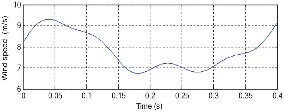
WS profile.
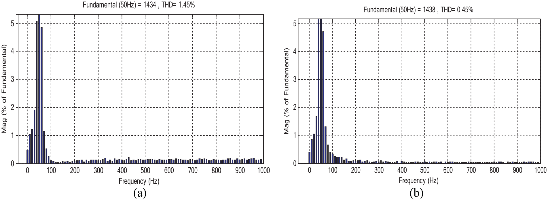
The THD value of the current: (a) DPC and (b) FONC.
Figure 10 represents the Ps of the strategies used, where the measured power follows the reference well with larger ripples in the case of DPC compared to the FONC technique. Also, Ps is greatly affected by WS due to the use of the MPPT to calculated the reference of the active power. Figure 11 represents the Qs for each of the traditional and suggested technique, where it is noted that the Qs is not affected by the change of WS and remains to take a constant value equal to 0 VAR with larger ripples in the case of the DPC compared to the FONC.
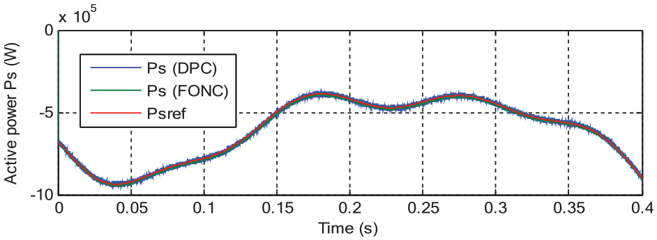
Ps.
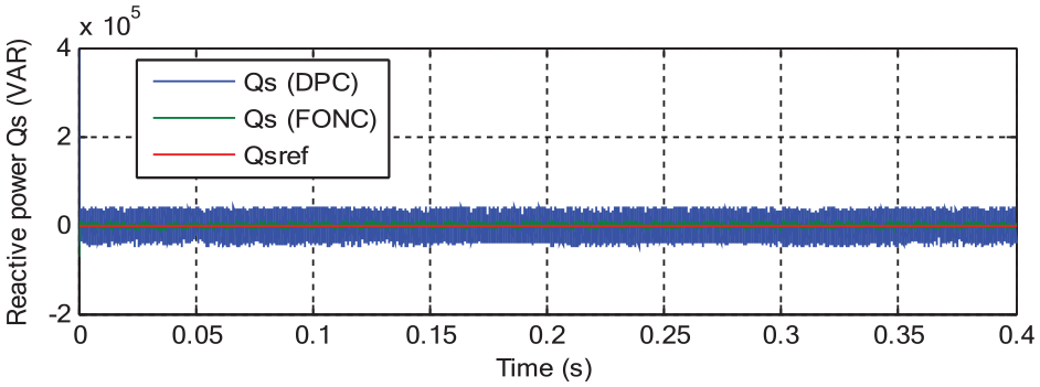
Qs.
The numerical results for the response time, ripple values, overshoot, and SSE of Qs and Ps for the DPC and FONC techniques are reported in Table 3. In Table 3, the reduction ratios of energy ripples, bypass, SSE, and response time of Ps and Qs of DFIG were calculated to show the superiority of each control compared to the other. Through this table, the suggested technique minimized the values of overshoot, SSE, and power ripples by 71.33%, 59.20%, and 65.71%, respectively, of the Ps compared to the DPC. In terms of Qs, the reduction percentages were 91.72%, 86.58%, and 85.74% for overshoot, SSE, and power ripples, respectively compared to the DPC technique.
The FONC gave unsatisfactory results in terms of the time response of the DFIG power compared to the DPC. The DPC reduced the response time of the Ps and Qs by rates estimated at 43.51% and 39.90%, respectively, compared to the FONC technique. It can be said that these ratios are undesirable and indicate a negative aspect of this proposed strategy and must be overcome in the future, as the PSO algorithm, GA technique, and gray wolf optimization can be used for this purpose. In the next test, the extent to which the suggested control is affected by a malfunctions in the machine will be studied compared to the behavior of the DPC control of DFIG-based DRWT system.
Second test
This second test is different from the first test, as the same WS used in the first test is used in order to conduct the study. In the second test, the system parameters are changed and the effect of the behavior of the FONC compared to the DPC technique is studied. This effect is studied by observing overshoot values, SSE, ripple reduction ratios, and response time for both Ps and Qs. In this test, the values of Rs and Rr are multiplied. Also, the values of Ls, Lm, and Lr are halved. The results of this test are represented in Table 4 and Figures 12–14. Despite the change in system parameters, the proposed strategy still provides satisfactory results in terms of power ripples, overshoot, and SSE. In Figure 12, the THD value of the current is given for each of the DPC and proposed FONC techniques. According to this figure, the FONC control reduced the THD value compared to the conventional DPC, which makes us say that the current quality is better in the case of the FONC. Therefore, the THD value of the current was 2.40% and 0.51% for each of the DPC and the FONC, respectively. So the percentage of reduction was 78.75% compared to the DPC, and this is a good percentage. In addition, the ratio of 78.75% indicates that the quality of the output current is of better quality in the case of FONC control compared to the DPC control, and that the shape of the current is sinusoidal with less ripples in the case of using the FONC strategy. On the other hand, it is noted that the FONC provided a better value for the amplitude of the fundamental of current signal compared to the DPC. The value of the amplitude in the case of using the FONC was 1433 A, while in the case of using the DPC technique, its value was 1430 A.
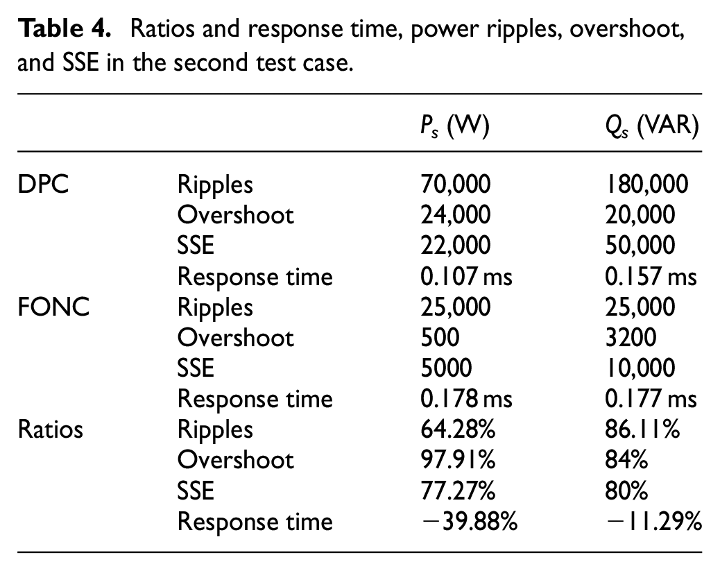
Ratios and response time, power ripples, overshoot, and SSE in the second test case.
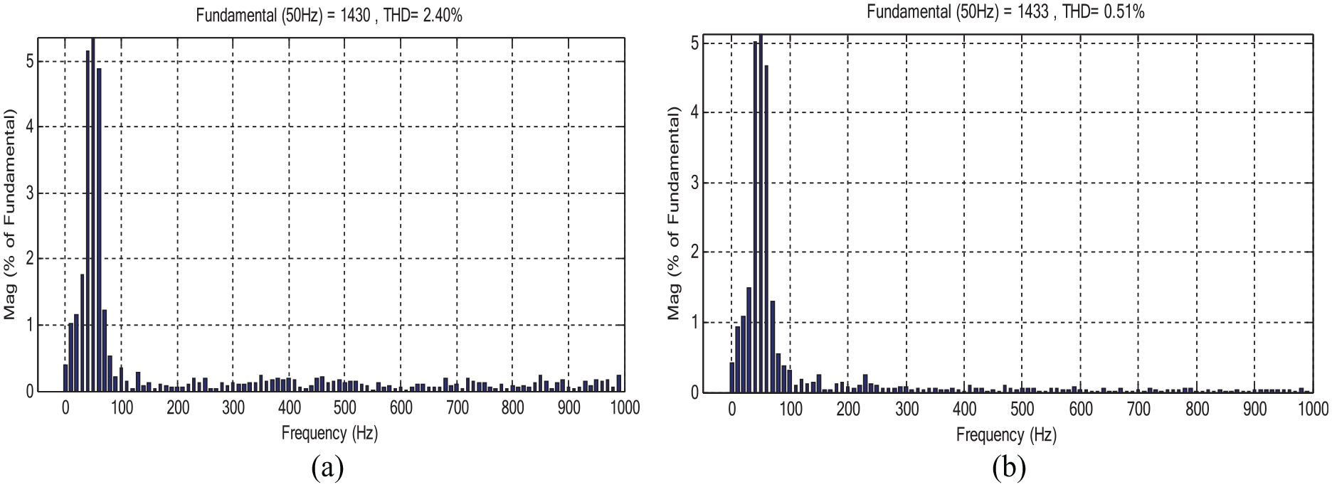
The THD value of the current: (a) DPC and (b) FONC.
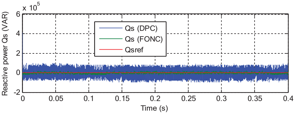
Qs.
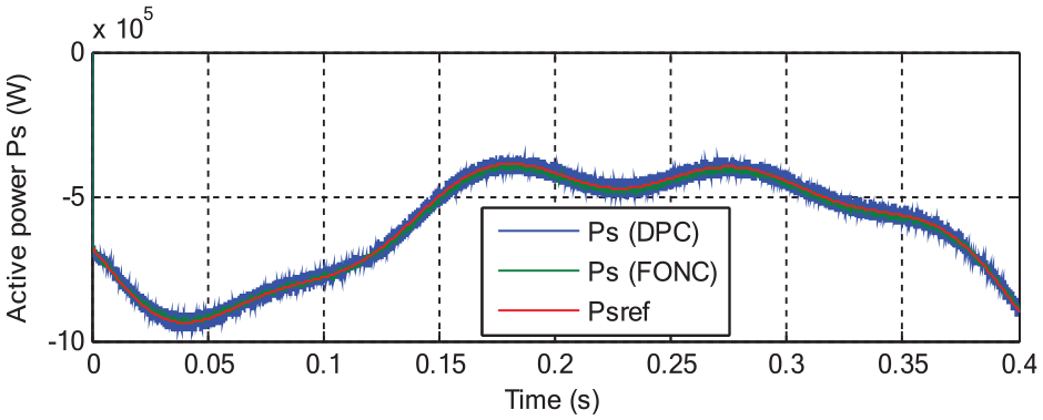
Ps.
In addition, the Ps and Qs follow the references well despite the change in the system parameters, with larger ripples in the case of the DPC compared to FONC (Figures 13 and 14). The form of the change of the Ps takes the change of the WS, and this is despite the change in the parameters of the machine, as the higher the wind speed, the higher the value of the Ps produced, and this is a good thing as a result of using the MPPT to calculate the reference value of the Ps. However, the Qs is not affected by the WS change and remains constant at the value of 0 VAR throughout the simulation period for the two controllers. Accordingly, changing the parameters does not affect the Ps and Qs ability to track the references, but it is noted that the effect is in increasing the value of each of the ripples, SSE, and overshoot as shown in Table 4. Table 4 presents the values and reduction ratios of energy ripples, overshoot, SSE, and response time for the controls used in this paper. Through this table, the suggested FONC control is to reduce the values of overshoot, SSE, and power ripples by 97.91%, 77.27%, and 64.28%, respectively, of the Ps. In terms of Qs, the reduction percentages were 84%, 80%, and 86.11% for overshoot, SSE, and power ripples. These high percentages indicate the efficiency of the proposed control compared to the DPC command on improving the characteristics of the system proposed for the study.
The proposed FONC strategy has a negative representation in providing an unsatisfactory time for the Ps and Qs compared to the DPC. So the classical control minimized the response time of the Ps and Qs by rates estimated at 39.88% and 11.29%, respectively, compared to the DPC. So, this negativity in the proposed control can be overcome by using other strategies based on artificial intelligence, such as the use of genetic algorithms in order to calculate the proposed control parameters, or the gray wolf optimization strategy can be used for this purpose. Also, the combination of neural networks and the PSO algorithm can be used as a suitable solution to increase the efficiency and performance of the FONC strategy.
Finally, the paper ends with a comparative study between the proposed FONC and some published works in terms of THD value and response time for Qs and Ps of the DFIG.
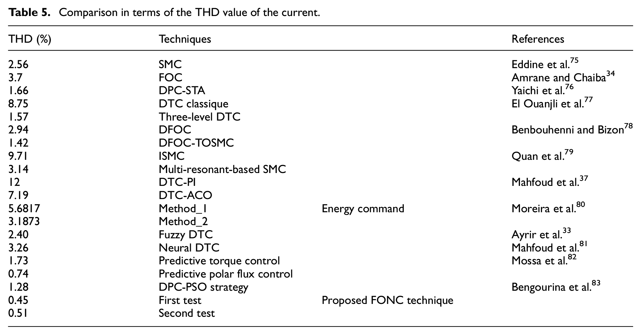
Table 5 represents a comparative study between the proposed control and some existing controls in terms of the THD value of the current. Through this table, it is noted that the proposed strategy gave a better value for THD, and this indicates the efficiency and effectiveness of the designed control in improving the quality of the current.
Comparison in terms of the THD value of the current.
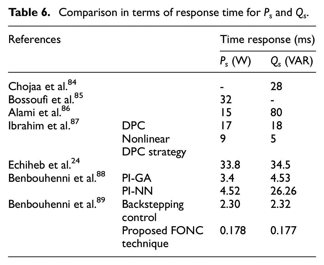
The designed control is compared with some published commands in terms of response time, where the results are recorded in Table 6. Through this table, the designed strategy gave a much better response time than several scientific works, which indicates the efficiency of the designed control in improving the characteristics of DFIG and this is it is desirable and reliable to use this control as a solution for controlling electrical machines.
Comparison in terms of response time for Ps and Qs.
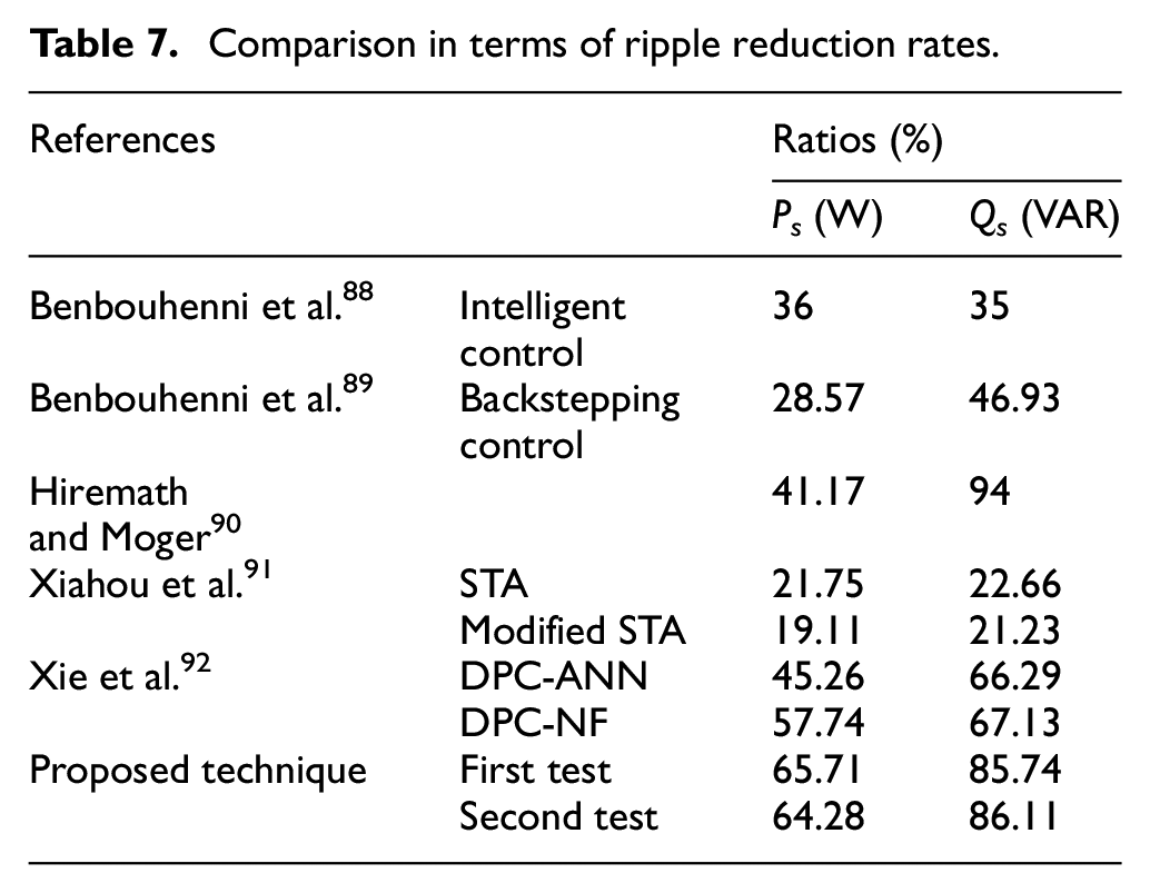
In Table 7, the work performed has been compared with some other works in terms of the percentages of Ps and Qs ripple reduction. These ratios recorded in the table show that the suggested control provided better ratios than these actions, which indicates the effectiveness of the suggested control and its ability to reduce Ps and Qs ripples of the DFIG-based MRWT system.
Comparison in terms of ripple reduction rates.
Conclusion
In this article, we presented the fractional-order neural control of the stator power of the DFIG supplied by two-level PWM strategy.
This study presents a comparison between the proposed control strategy and traditional DPC for a DFIG-based dual-rotor wind turbine system. The simulation results show that the suggested control with PWM is an excellent solution for a DFIG-based dual-rotor wind turbine. Simulation results (related to tracking tests and robustness tests) clearly show good performances in power ripples, overshoot, and SSE compared to classical techniques, where the proposed strategy works to minimize the ripples of the active and reactive power by rates estimated at 65.71% and 85.74%, respectively, in the first test, and in the second test, the rates were estimated at 64.28% and 86.11% for each of the active and reactive power, respectively. Also, the proposed control reduced the THD value of the current by good percentages estimated at 68.96% and 78.75% in both the first and second tests, respectively. The results of the analysis show that the proposed control improved the overshoot value of the active power compared to the traditional control in good percentages, as the percentages of reduction were 71.33% and 97.71% in each of the first and second tests, respectively. Regarding the reflexive capacity, the percentages of reduction were 91.72% and 84% for each of the first and second tests, respectively, compared to the traditional control. The current research work is restricted and limited given that the results are from simulations only. Besides, examine the designed strategy in case of high voltage dipping. Accordingly, enhancing the robustness of the system proposed in this work in light of previous concerns will be implemented in future papers. The disadvantages of the proposed control will be overcome by the interactions of this new strategy with various smart strategies, such as gray wolf optimization, fuzzy logic controller type 2, and Anty colony optimization.
As a future work, the suggested control will be accomplished and implemented experimentally, and compared with other proposed controls for wind energy generation systems.
Footnotes
Appendix A
where, Te is the torque of DFIG, Tr is the load torque, J is the inertia, f is the viscous friction coefficient, and Ω is the mechanical rotor speed.
where, Qs is the reactive power and Ps is the active power.
Equations (A4) and (A5) represent the flux and voltage in the rotor.
where, Lr is the rotor inductance, Vdr and Vqr are the direct and quadrature stator voltages, Rr is the rotor resistance, Idr and Iqr are the direct and quadrature rotor currents, ψdr and ψqr are the direct and quadrature rotor voltages.
Equations (A6) and (A7) represent the flux and voltage in the stator.
where, Ls is the stator inductance, Vds and Vqs are the direct and quadrature stator voltages, Rs is the stator resistance, Iqs and Ids are the direct and quadrature stator currents, ψds and ψqs are the direct and quadrature stator voltages.
Appendix B
DRWT is a type of turbine that appeared in recent years as a solution to increase the value of power gained from wind and increase the stability of the generation system.10,25 This type of turbine depends on the use of two turbines rotating in the same direction and located on the same axis, where the resulting torque is the sum of the torque of the two turbines. This type of turbine has been discussed in several scientific works.25–29 In Benbouhenni, 32 DRWT offers 23%–30% more power than conventional turbines. Equation (A8) represents the total torque of the DRWT.
where, T1 and T2 are the torque of the first and second turbines and TDRWT is the total torque of the turbine.
Equation (A9) and (A10) represent each of the torques of the two turbines used to implement DRWT,27,28 where the value of the torque of each turbine is related to wind speed (w), coefficient of power (Cp), and tip speed ratio (λ).
Where, R1 and R2 are the blade radius of the first and second turbines, ρ is the air density, λ1 and λ2 are the tip speed ration of the first and second turbines
Equation (A11) and (A12) represent each of the λ of the two turbines, where the WS is large, the λ is small, which makes the torque value large, and this is a good thing. But in the case of a lower WS, the λ is large, which makes the torque small, and this is not desirable.
where, V1 and V2 are the speed of the first and second turbines. w1 and w2 the mechanical speed of the first and second turbines.
Equation (A13) represents the WS used to calculate the torque in the second turbine. As it is known, the WS in the second turbine is different from the WS in the first turbine. The WS in the second turbine is related to the distance between the two turbines (x) and the WS before the first turbine (V1) and with a constant coefficient (CT) that takes the value of 0.9. In this work, the distance between the two turbines is 15 m.10,32
In DRWT, the torque of the two turbines is greatly affected by the value of Cp and this parameter has a great relationship with the change in the value of each of the λ and pitch angle (β). Equation (A14) represents the expression Cp used for torque calculation.
Declaration of conflicting interests
The author(s) declared no potential conflicts of interest with respect to the research, authorship, and/or publication of this article.
Funding
The author(s) disclosed receipt of the following financial support for the research, authorship, and/or publication of this article: This project was supported by the Scientific Research Center at Buraydah Private Colleges under the research project# BPC-SRC/2022-012.