
Abstract
Wind energy is known as one of the most efficient clean renewable energy sources and has attracted extensive research interests in both academic and industry fields. In this study, the effects of turbulent wind and voltage disturbance on a wind turbine drivetrain are analyzed, and a wind turbine drivetrain dynamic model combined with the electric model of a doubly fed induction generator is established. The proposed model is able to account for the dynamic interaction between turbulent wind, voltage disturbance, and mechanical system. Also, the effects of time-varying meshing stiffness, transmission error, and bearing stiffness are included in the mechanical part of the coupled dynamic model. From the resultant model, system modes are computed. In addition, by considering the actual control strategies in the simulation process, the effects of turbulent wind and voltage disturbance on the geared rotor system are analyzed. The computational results show that the turbulent wind and voltage disturbance can cause adverse effects on the wind turbine drivetrain, especially the gearbox. A series of parametric studies are also performed to understand the influences of generator and gearbox parameters on the drivetrain system dynamics. Finally, the appropriate generator parameters having a positive effect on the gearbox in alleviating the extreme loads and the modeling approach for investigating the transient performance of generator are discussed.
Introduction
Today, with the rapid development of wind power generation technology, in order to guarantee a reliable and robust wind turbine generation system design, research on the interaction of different parts of a wind turbine in the presence of turbulent wind and voltage disturbance is warranted. In a wind turbine system, mechanical transmission is normally used to connect the electrical machine and the wind load in a low-speed, high-torque application. Hence, the transmission is the most important component that can directly affect the safety and stability of the wind turbine. This geared rotor system is usually working under the coupled excitations of wind and electric loads as well as the internal excitation due to the gear transmission error and shaft dynamics. Therefore, to ensure the reliability of the wind turbine design, a dynamic model of the wind turbine drivetrain is proposed.
In the past few years, the dynamic problems of the wind turbine drivetrain have been studied extensively. For example, by building the planetary gear train models and considering the internal excitation caused by time-varying meshing stiffness, Kahraman1,2 and Parker et al. 3 analyzed the vibratory responses of the planetary gear train. In 2007, a research group from National Renewable Energy Laboratory used different methods to explore approaches to improve the reliability of a wind turbine gearbox. 4 Helsen et al.5,6 conducted numerical simulations of the dynamic responses of a wind turbine gearbox by employing different modeling methods, and the effects of the different supporting types on the gearbox were studied. Todorov et al. 7 acquired the natural frequencies, mode shapes, and amplitude–frequency characteristics of a wind turbine drivetrain by building a torsional model that consists of 10 rigid bodies and 8 degrees of freedom (DOFs). Li et al. 8 analyzed the transient stability of a grid-connected wind turbine with induction generator by building a detailed squirrel cage induction generator (SCIG) model and considering flexible blades. Qin et al.9,10 applied mechanical system dynamics methods to investigate vibrations and load situations of the gears and bearings in the gearbox and made a great contribution to the optimization problems about gear transmission systems.
The above studies provided valuable guidance for the optimum design of wind turbine drivetrain systems and the assessment of their reliability. However, a coupled model that considers the effects of the dynamic interactions between electrical and mechanical components and wind load is rarely mentioned in the previous publications. In this work, a dynamic model that combines all electrical, mechanical, and aerodynamic effects of a 1-MW wind turbine drivetrain is developed. Applying this model, first, the modes of the drivetrain are calculated, and second, the interaction between turbulent wind, voltage disturbance, and drivetrain is analyzed. In addition, the effect of variation in generator parameters on the gearbox and the effect of different degrees of freedom of the gearbox on the transient performance of the generator are investigated.
Mathematic modeling
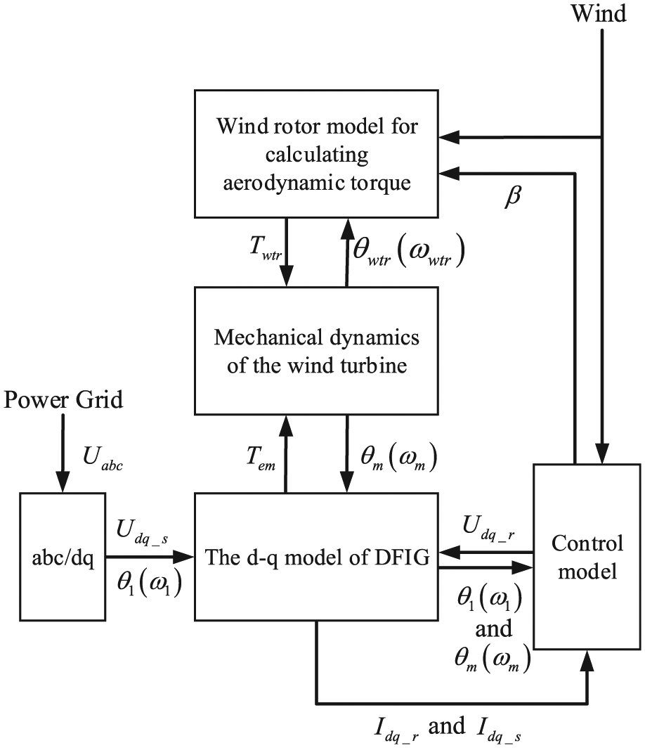
The 1-MW wind turbine drivetrain mainly consists of a wind rotor, a low shaft, a gearbox, a high shaft, and a generator system as shown in Figure 1. The generator stator is directly connected to the power grid, and the generator rotor excitation current is controlled by two bidirectional pulse-width modulation (PWM) converters. The electrical power can be transmitted into the power grid by the stator and the rotor.
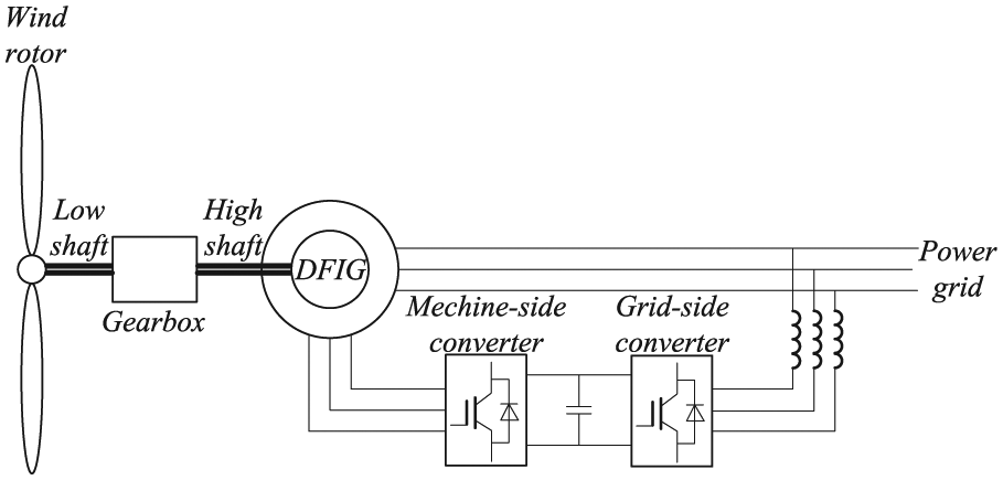
Brief model of a grid-connected wind turbine with DFIG.
Wind rotor model
The wind rotor model is formulated in this section. The aerodynamic power

where
The tip speed ratio
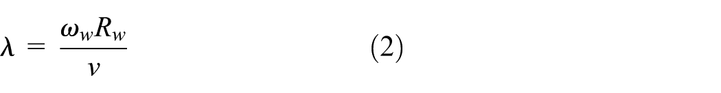
where
The power coefficient
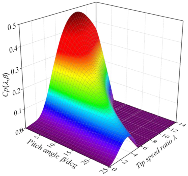
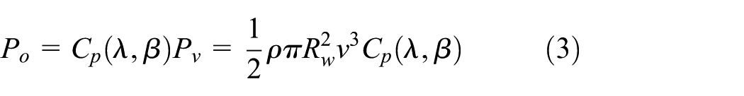
The output power
Furthermore, the aerodynamic torque
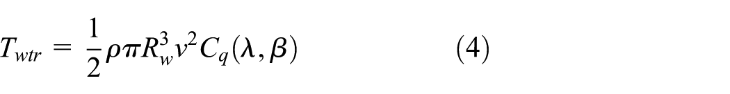
where
Mechanical model
The wind turbine mechanical model consists of a wind rotor, a drivetrain, and a generator rotor. The drivetrain has a gearbox with three stages, which includes a low-speed planetary gear stage (three identical planets with spur teeth, sun and fixed ring wheel) and two high-speed parallel gear stages (spur gear pairs). Applying lumped parameter modeling, the dynamic model can be realized as shown in Figure 3. The model consists of blades, a hub, a planet carrier, gears, a generator rotor, and elastic shafts. It considers the effects of the bending flexibility of the blades, meshing stiffness, meshing error, supporting stiffness, and shaft torsional stiffness. The blade break point where the spring is assumed to be placed is the end of blade. All the rotational coordinates associated with the drivetrain components are included, but only the radial translations of planet carrier and gears are considered. Thus, the model has 12 rigid bodies and 30 DOFs.

Dynamic model of transmission system with 30 degrees of freedom.
As shown in Figure 3,
The rotational directions of the components are shown in Figure 3. The planet gears adopt the
where
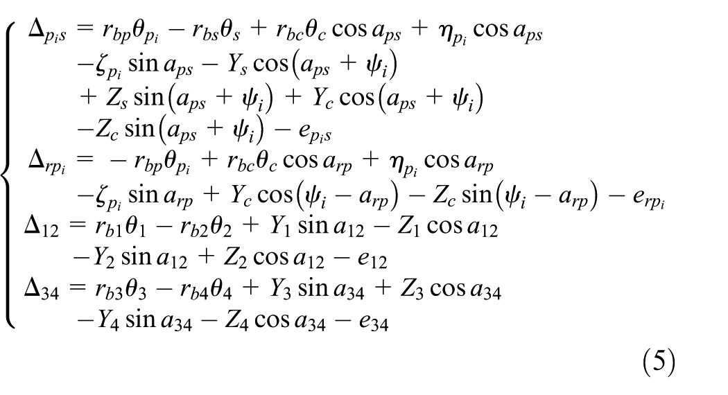
The dynamic meshing forces

In this formulation, the supporting stiffness and damping for the planet carrier and every gear are also considered. As shown in Figure 4,

Model of bearing supporting stiffness and damping.
It is assumed that the ring is fixed. According to Newton’s second law of motion, the wind turbine dynamic system equations are described as:
1. Wind rotor and low-speed shaft equations

2. Gearbox and high-speed shaft equations

3. Generator rotor dynamic equations

The wind turbine system dynamic equations can also be written as

where
Bearing supporting stiffness and damping
In this analysis, an empirical formula is adopted to calculate the bearing stiffness. The supporting stiffness

where
The supporting damping

where
Mesh stiffness and damping
In the meshing process of spur gear, there are a couple of meshing conditions that are single and double tooth meshing situations. Therefore, it causes meshing stiffness

where
The values of the meshing damping of the gear pairs
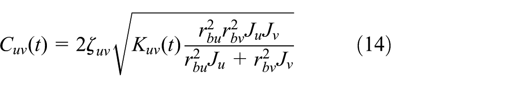
where
Static transmission error
The transmission error of the gear pairs

where
Torsional stiffness and damping of shafts
In this analysis, elastic deformation of shaft only considers torsional deformation. The torsional stiffness
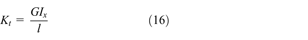
where G is the shear modulus of the shaft,
The torsional damping

where
Doubly fed induction generator model
In this derivation, the effects of magnetic saturation and iron losses are neglected in the synchronous rotating reference frame (

where

where

where p is the number of pole pairs. Finally, the stator active power

Control strategy of the wind turbine
Pitch control
Above the rated wind speed, due to the limitation of the mechanical loads and the capacity of electrical devices, the output power of the wind rotor should be limited. As mentioned in section “Wind rotor model,” the aerodynamic power is related to wind speed and power coefficient
In this analysis, in order to simplify the pitch control strategy, a proportional–integral–derivative (PID) controller is implemented for controlling the pitch angle. The angle command is limited to the range of
As shown in Figure 5,

Control structure of pitch control.

Desired generator mechanical rotor speed curve.
At point A, wind speed is 3 m/s, which is the cut-in wind speed at which the doubly fed induction generator begins to output electrical power to grid. At point B, wind speed is 12 m/s, which is the rated wind speed at which the DFIG arrives at the rated power.
Stator flux–oriented control
The DFIG is controlled in the synchronous rotating
The stator flux equations are rewritten as vector equations

where
Attaching the


where
Thus, the stator current equations are expressed as
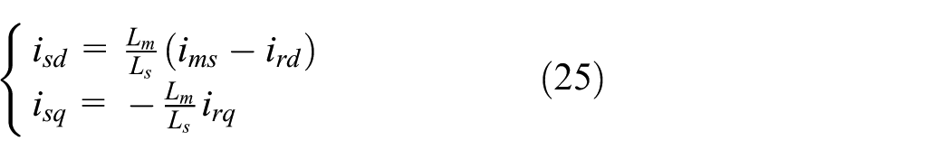
Neglecting the stator resistance, the

where

Based on equation (27), using the stator flux–oriented control strategy, the stator active power is controlled by the
The rotor flux equations are rewritten as

where
So, the rotor voltage equations are rewritten as

In this derivation, the control of active and reactive power is based on equation (27), while the rotor current controller is designed based on equation (29). Hence, the overall wind turbine model is built, as shown in Figure 7.
Simulation of the wind turbine by MATLAB/Simulink.
Numerical simulations
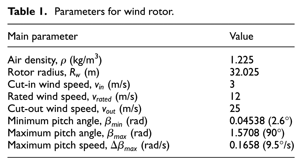
In this section, numerical simulations are conducted. The main parameters of the wind turbine are shown in Table 1, the main parameters of the drivetrain are shown in Table 2, and the main parameters of the generator are shown in Table 3.
Parameters for wind rotor.
Parameters for driven train.

Parameters for DFIG.

Modal analysis
Neglecting the system damping and meshing error, the meshing stiffness and the bearing supporting stiffness are the average value. Thus, the system un-damped free vibration differential equation is defined as

It is assumed that the mode shape matrix is

where

The un-damped natural frequencies are shown in Table 4. The mode shapes are shown in Figure 8.
Categorized natural frequencies for the wind turbine.

DOF: degree of freedom.
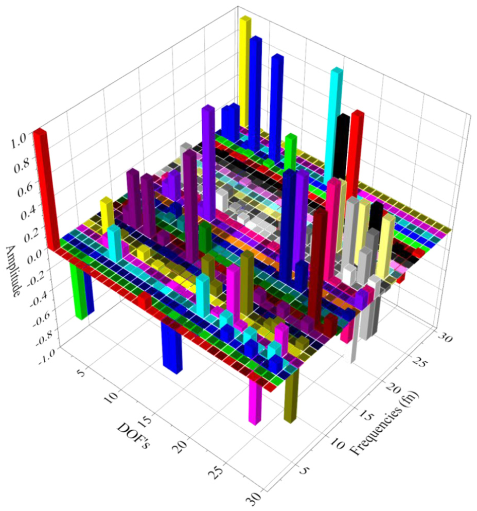
Mode shapes of the wind turbine drivetrain.
As shown in Figure 8 and Table 4, the mode shapes of the wind turbine drivetrain consist of rotational modes, translational modes, and rotational–translational modes. The amplitude of rotational vibration is greater than translational vibration, so the main pattern of the system vibration is represented as rotational vibration. Hence, on the condition of the external exciting torques such as the aerodynamic torque and the electrical torque, the rotational vibration amplitude of the system may increase, especially when resonance occurs. Besides, the severe rotational vibration can influence the fatigue life of shafts and gears.
Dynamic response
In the condition of the three-phase ideal voltage, two kinds of wind speed models are considered as the external excitation of the wind turbine system, especially gearbox. The wind models include a steady state (12 m/s) and turbulent one (average wind speed is 12 m/s and turbulent intensity is 20%), as shown in Figure 9. The turbulent one is based on the linear auto-regressive wind speed model considering the variety of field conditions, the wind spectrum characters, and the traits of buildings, which is regarded as more representative than others.

Wind time series.
According to equations from sections “Mathematic modeling” and “Control strategy of the wind turbine,” under the conditions of the two kinds of wind models, the response of the model, as shown in Figure 7, is computed. Figure 10 illustrates that by comparing with the steady wind condition, the turbulent wind will cause more disturbances on pitch angle, generator mechanical angular velocity, generator power, and electrical torque. Besides, the calculation results show that under the condition of turbulent wind, the components in the gearbox will vibrate more intensively, such as the planet carrier shown in Figure 11. The dynamic meshing force and amplitudes counting are shown in Figure 12. Because of the limitation of space, only the meshing force between gear 3 and gear 4 is given. The meshing force has significant time variation. The wind speed fluctuation will aggravate the trait. In the turbulent wind case, the range of meshing force of a gear pair rise by 60% over the force in the steady wind case so that it has a negative influence on the fatigue life of gears. The statistic results will make a contribution to provide a theoretical basis for the gear parameter optimization and reliability assessment.

Pitch angle and generator parameters curve: (a) pitch angle, (b) generator mechanical angular velocity, (c) generator stator active power, (d) generator rotor active power, (e) generator stator reactive power, and (f) generator electromagnetic torque.

Vibration angular acceleration of planet carrier.

Meshing force between gear 3 and gear 4 and amplitude counting results: (a) dynamic meshing force of gear 3 and gear 4 and (b) meshing force amplitude counting.
Finally, under the turbulent wind condition, the effects of voltage sag on the dynamic responses of the drivetrain are also studied. The power grid voltage sags to 20% at
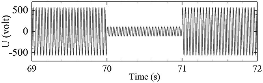
Voltage sag.
As shown in Figure 14, the voltage will cause severe fluctuation of generator electromagnetic torque which directly acts on the gearbox through a coupling. So, the fluctuation may damage gear tooth and influence the gearbox life.

Electromagnetic torque and meshing force: (a) generator electromagnetic torque and (b) dynamic meshing force of gear 3 and gear 4.
Parametric studies
First, the effects of rotor and stator resistance variation on the gearbox during voltage sag are discussed. Because of the limitation of space, only effects on meshing force between gear 3 and gear 4 are given.
As shown in Figure 15, under the condition of voltage sag shown in Figure 13 and steady wind shown in Figure 9, different values of resistance have significant effects on the maximum meshing force between gear 3 and gear 4. With the increase in resistance, the maximum meshing force will reduce. Therefore, in the process of generator design, not only can electric capacity be considered but also the interaction between gearbox and generator should be contained.

Effects of generator parameters on gearbox during voltage sag: (a) the relationship between maximum meshing force and stator resistance and (b) the relationship between maximum meshing force and rotor resistance.
And then, the effects of different freedom models of the gearbox on the transit performance of the generator system are also investigated. In the section, a simplified gearbox model is proposed. Based on the detail gearbox model, the simplified model only considers the rotational freedom of components of gearbox, so its dynamic equation can be expressed as

where
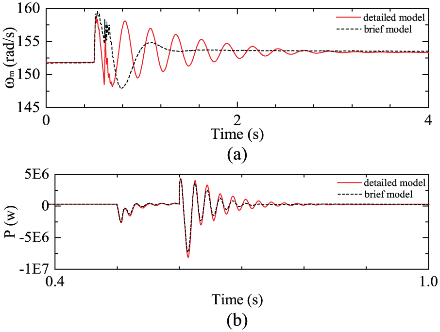
Under the conditions of wind speed 12 m/s, the power grid voltage sags to 80% at
Under the conditions of wind speed 12 m/s, the power grid voltage sags to 10% at
Under the conditions of wind speed 7 m/s, the power grid voltage sags to 10% at
Under the conditions of wind speed 12 m/s, the power grid voltage respectively sags to 10% at

Transient response of the generator system: (a) the transient response of angular velocity of generator rotor and (b) the transient response of active power of generator.

Transient response of the generator system: (a) the transient response of angular velocity of generator rotor and (b) the transient response of active power of generator.
Transient response of the generator system: (a) the transient response of angular velocity of generator rotor and (b) the transient response of active power of generator.

Transient response of the generator system: (a) the transient response of angular velocity of generator rotor and (b) the transient response of active power of generator.
It can be seen in these figures that the fault of power grid both for brief and detailed model can lead to large oscillation of active power and rotational speed of generator rotor. Furthermore, the results clearly show a few differences in the transient responses with different freedom models of gearbox. In the high wind speed and extreme fault of power grid, the effects of freedom of gearbox on transient responses of the generator system are significant and cannot be neglected. The freedom of gearbox plays a dominant role in transient responses of generator system; therefore, in order to deeply research the transient stability of a wind power generation system, a detailed model of gearbox should be carefully considered.
Conclusion
In this study, in order to accurately analyze the effects of turbulent wind and voltage sag on the 1-MW wind turbine gearbox, a detailed wind turbine drivetrain model which has 12 rigid bodies and 30 DOFs has been proposed by considering the bending flexibility of the blades, meshing stiffness and damping, meshing error, bearing stiffness and damping, and torsional flexibility of the drivetrain shaft.
First, modal analysis is computed, and the results show that the main pattern of the system vibration is represented as rotational vibration. Under the influence of external exciting torques, the system has the potential possibility for resonance. Second, by incorporating the aerodynamic torque calculation model, the electromagnetic transient models of DFIG, and control strategies, the dynamic behaviors of the gearbox system can be analyzed. The results show that the disturbance produced by turbulent wind will increase the vibration level of components inside and also expand the variation range of meshing force. This potentially can cause premature fatigue of the gearbox system. Third, under the condition of turbulent wind, the effect of voltage sag is analyzed. The results show that the electromagnetic torque fluctuation produced by voltage sag will cause severe impact on the gears. Finally, the effects of generator parameter variation on the gearbox and effects of different freedom models of the gearbox on transient responses of the generator system are researched. The results show that parameters of the generator play an important role in decreasing gearbox loads in extreme situation and the importance of the dynamics of gearbox system. This analysis also demonstrated the salient features of the proposed wind turbine drivetrain model coupled incorporating aerodynamic and electrical effects and its usefulness in predicting design reliability.
Footnotes
Academic Editor: José Tenreiro Machado
Declaration of conflicting interests
The author(s) declared no potential conflicts of interest with respect to the research, authorship, and/or publication of this article.
Funding
The author(s) received no financial support for the research, authorship, and/or publication of this article.