
Abstract
In order to solve the dynamic analysis and chaotic motion control problems of the current-mode-controlled Boost converter system, a state equation model in the continuous current mode is established. The evolutionary path of the periodic motion of the system through the doubling bifurcation to the chaotic motion is analyzed by the bifurcation diagram, Poincaré sections and phase portraits. Then, according to the fundamental principle of the resonant parametric perturbation (RPP) method, a controller is designed based on the model-free adaptive control (MFAC) method to output the perturbation amplitude, and the disturbance quantity is calculated according to the perturbation amplitude. By adding a small amplitude disturbance to the controllable parameter of the controlled system, the chaotic motion of the system is guided to expected periodic orbit. The advantage of this method is that no precise mathematical model (PMM) of the system is required. At the same time, the design of the controller is simple and easy to implement.
Introduction
Since the meteorologist Lorenz proposed chaos theory, researchers have discovered chaos in many engineering fields. 1 As the core part of switching power supply, DC-DC converter is widely used in instruments, electric vehicles, green energy and other systems.2–4 In practical operation, DC-DC converter will produce complex and abundant nonlinear physical phenomena (such as bifurcation, chaos, etc.),5,6 which will not only greatly affect the stability of the converter, but also cause the converter system failure. 7
In order to suppress the chaotic motion of DC-DC converter system, researchers have made active exploration. Ito et al. 8 adopted the strategy of perturbation pulse-frequency modulation to realize chaotic motion control of Buck converter. Jia 9 researched the bifurcation and chaotic motion generated by the voltage-mode-controlled Buck converter with the change of input voltage. She proposed a self-feedback chaos control method, which successfully stabilized the chaotic motion of Buck converter to period-1 orbit. In view of bifurcations and chaos in Buck converter system, Luo et al. 10 adopted the periodic pulse control method to adjust the output pulse width of the comparison amplifier and controlled the system to the desired periodic motion. Zhang et al. 11 adopted sinusoidal voltage compensation strategy based on the monodromy matrix theory to reduce the duty cycle of the system. The chaos control of V 2 controlled Buck converter system was realized. El Aroudi et al. 12 extracted control signals from the errors between the inductive current and the constant parameters of the converter system, proposed a new self-compensation technique, and realized the chaotic motion control of the DC-DC converter system. Morcillo et al. 13 analyzed the evolutionary path of the DC-DC converter system leading to chaos through period-doubling bifurcation with the change of circuit parameters. An adaptive ramp control strategy with self-tuning offset and amplitude was proposed to realize the chaotic motion control of the system within a wide range of circuit parameters. Fu et al. 14 used Integral Absolute Error (IAE) as the control performance indicator, and introduced Particle Swarm Optimization (PSO) and Genetic Algorithm (GA) respectively to find the optimal value of PID controller parameters, and the optimized PID controller was applied to realize chaos control of the voltage-mode-controlled Buck converter system. Wu et al. 15 explored the bifurcation behavior and chaotic motion of the Buck-Boost converter system. Based on the exponential delayed feedback control method, the feedback adjustment function in the parameter feedback control law was subtracted from the reference current. The feedback intensity was adjusted by setting the adjustment coefficient in the feedback adjustment function. The improved control strategy was used to control the system to stable periodic orbit. Deivasundari et al. 16 uncovered the chaotic phenomena of a master-slave controlled parallel Buck converter system. The system was controlled to regular periodic orbit successfully by adding an optimal phase-shifted sinusoidal disturbance to the reference voltage. Bao et al. 17 controlled the chaotic motion of the system to a stable periodic motion by introducing a suitable ramp compensation current into the current-mode-controlled Boost circuit. Luo et al. 18 studied the voltage-mode-controlled Buck converter system and used OGY method to suppress the chaotic motion of the system. Lu et al. 19 adopted the time-delay feedback chaos control method to realize the chaos control of the current-mode-controlled Boost converter system. Yang et al. 20 studied the dynamics and chaotic motion of the switched-inductor Buck-Boost converter system with the memristive load, and realized chaos control by adopting resonant parametric perturbation (RPP) method. The principle of RPP chaos control method is to change the chaotic motion state of the system into regular motion state by applying a specific frequency of micro-perturbation to the circuit parameters. 21
Over the years, researchers have made some achievements in the study of chaos control of DC-DC converter systems through continuous efforts. However, most of the existing studies rely on the precise mathematical model (PMM) of the controlled system to design the controller, which will not be applicable or cannot obtain satisfactory control effect when the system is difficult to accurately model. For this reason, researchers have explored the control methods that do not depend on the precise model of the controlled system. For voltage-mode-controlled Buck converter system, Huang 22 used Radial Basis Function Neural Network (RBFNN) to learn dynamic characteristics of chaotic system of Buck converter, and adopted the trained RBFNN model to realize chaos control. Ling 23 took current-mode-controlled Buck-Boost converter system as the research object, and introduced GA to optimize the parameters of Back Propagation Neural Network (BPNN) controller, and used the optimized BPNN controller to output the perturbation amplitude to realize chaos control. Although researchers have actively explored the chaos control of DC-DC converter systems without the need for PMM of the system, the current research results are still few and need to be further explored and deepened.
Model-free adaptive control (MFAC) method can effectively solve control problems that are difficult to be modeled accurately because of its advantages of not relying on the mathematical model information of the controlled system and requiring only the input/output (I/O) data of the controlled system. 24 Therefore, it is widely used in various fields such as urban road traffic network control, 25 network communication delay compensation, 26 robot motion control,27,28 electric vehicle and motor control,29,30 etc. However, the study of introducing MFAC method into chaos control of DC-DC converter system has not been reported publicly.
Therefore, aiming at the chaos control problem of DC-DC converter system, this paper proposes a model-free adaptive chaos control (MFACC) method which does not depend on the PMM of the system. Based on the idea of combining RPP method and MFAC method, a model-free adaptive chaos controller is designed only using the I/O observation data of the system, so as to output the perturbation amplitude to be determined in the disturbance term. By substituting the perturbation amplitude into the calculation formula of the disturbance term, the disturbance quantity can be calculated. The chaotic motion generated in the system can be guided to a stable periodic orbit by perturbing the controllable circuit parameter. By using MATLAB simulation software and taking the Boost converter system as an example, the results show that the chaos control method proposed in this paper is feasible and effective.
Chaotic motion analysis of the system
In this paper, the chaotic motion control problem of the current-mode-controlled Boost converter is studied. The circuit diagram of the system is shown in Figure 1. In Figure 1, the main circuit of the Boost converter is composed of the input voltage Vin, an inductor L, a MOSFET switch S, a diode D, a capacitor C, a resistor load R and other electronic components. To facilitate the analysis of the working principle of the circuit, assume that all the components in the circuit system shown in Figure 1 are ideal.
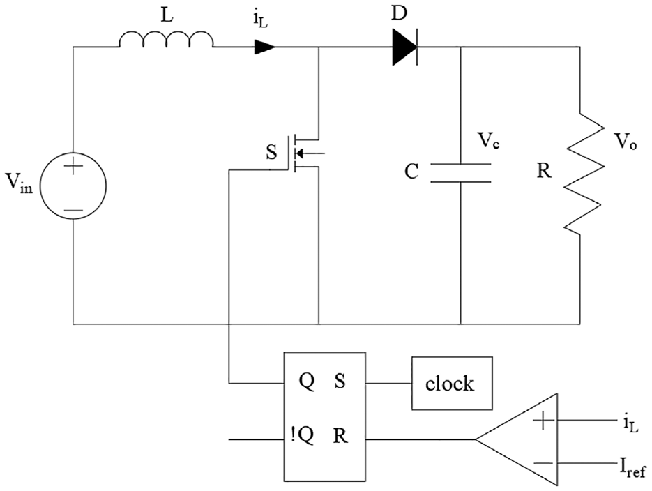
Schematic diagram of the current-mode-controlled Boost converter.
According to the circuit schematic diagram of the system shown in Figure 1, and combined with the theoretical knowledge of related circuit, the working principle is analyzed.
31
Using the laws of KCL and KVL, the inductive current iL and the capacitive voltage vc are determined as the state variables of the system, that is
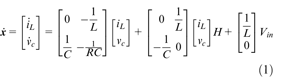
where H is the signal values of switch S on and off, 1 corresponds to on and 0 corresponds to off.
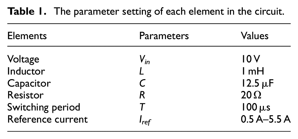
When some circuit parameters of the current-mode-controlled Boost converter system change, the system may exhibit rich and complex dynamic behaviors. According to the stroboscopic mapping sampling method, the state variables (vc and iL) of the system are sampled respectively at the time t = nT (where T is the switching period, n = 1,2,3,…). And take Poincaré cross sections at the time t = nT. The Boost circuit parameters are selected as shown in Table 1. Iref is used as the bifurcation parameter to conduct numerical simulation of the system dynamics. The bifurcation diagram of the system inductive current iL changing with Iref is shown in Figure 2.
The parameter setting of each element in the circuit.
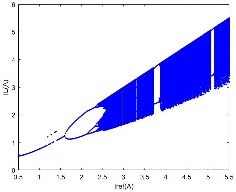
The bifurcation diagram of iL with Iref as the bifurcation parameter.
In Figure 2, when the reference current Iref changes within a specific range, the system shown in Figure 1 has stable period-1 motion, but with the increase of Iref, bifurcation will occur and the system will eventually evolve into chaotic motion. There are some periodic windows after the system has gone into chaos, and this is one of the typical characteristics of chaotic motion of nonlinear system.
Figure 3 shows the Poincaré section and phase portrait of period-1 motion of the system. It can be seen from Figure 3 that when Iref = 0.7 A, a point is shown on the Poincaré section. The phase portrait is a closed curve. The Poincaré section and phase portrait of period-2 motion of the system are shown in Figure 4(a) and (b) respectively. In Figure 4, when Iref = 1.8 A, there are two points on the Poincaré section, and the phase portrait is partially dented compared with the orbit of period-1. Figure 5 is the Poincaré section and phase portrait of the chaotic motion of the system. Furthermore, from Figure 5, when Iref = 2.75 A, the Poincaré section presents a point set with fractal structure. The phase portrait has infinitely nested self-similar structures.
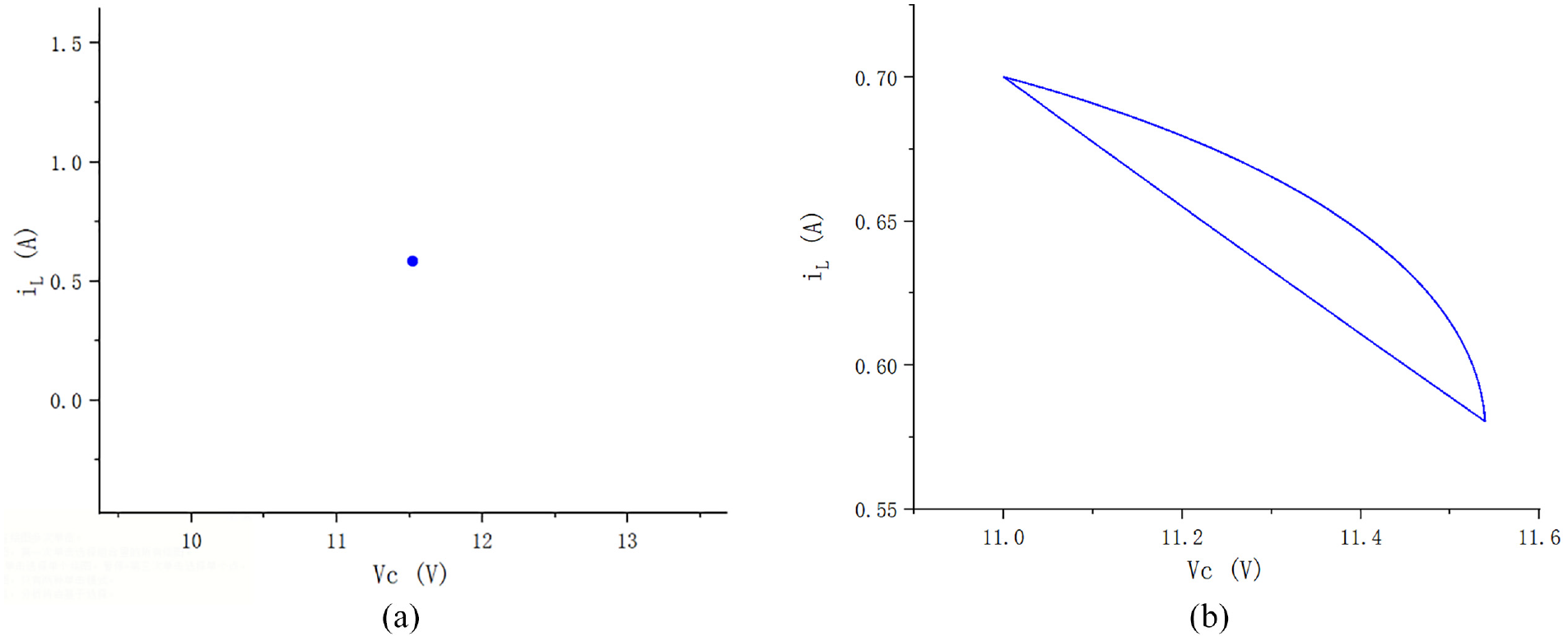
Period-1 motion generated in the system (Iref = 0.7 A): (a) the Poincaré section and (b) the phase portrait.
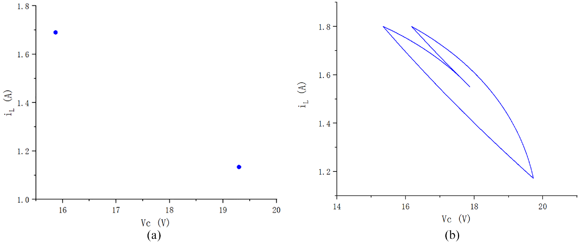
Period-2 motion generated in the system (Iref = 1.8 A): (a) the Poincaré section and (b) the phase portrait.
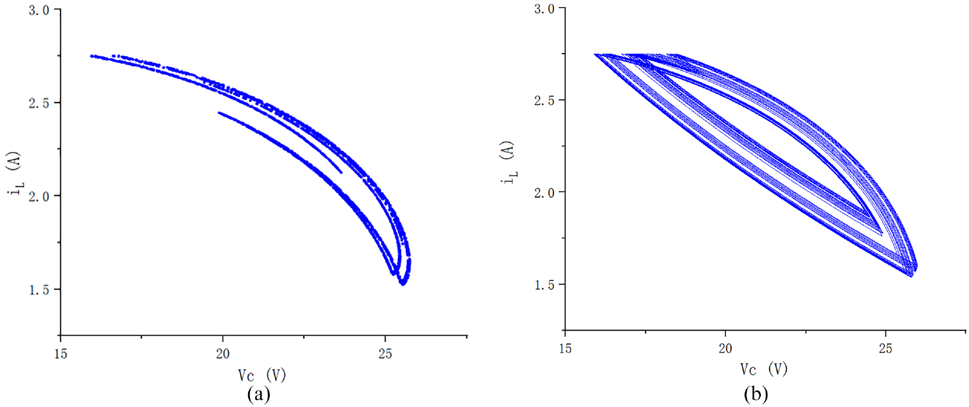
The chaotic motion generated in the system (Iref = 2.75 A): (a) the Poincaré section and (b) the phase portrait.
MFAC of the chaotic motion
Control strategy
According to the analysis in Section 2, when Iref changes within a certain range, the system evolves into chaotic motion through period-doubling bifurcation (when Iref = 2.75 A, the system is chaotic). It can be seen that if the value of Iref is changed reasonably, the survival conditions of the chaotic motion can be eliminated, so as to achieve the purpose of suppressing the chaotic motion.
Based on this, according to the principle of RPP method, a MFAC strategy is proposed for the chaotic motion of the Boost converter. Firstly, a circuit parameter Q which has a great influence on the system and is easy to change is selected, so that the survival conditions of the chaotic motion can be changed by perturbation of Q, and the system can be guided to expected periodic orbit. Secondly, based on the idea of MFAC, the equivalent dynamic linearization of the Boost converter system is carried out. That is to say, the pseudo partial derivative (PPD) is estimated online by the I/O data of the system to build the dynamic linearized data model of the system. After obtaining the model, the controller is further designed. By constantly extracting the effective information in the I/O data of the system, the controller can accurately learn the nonlinear characteristics of the controlled system, so as to determine the reasonable perturbation amplitude applied to Q.
The structure diagram of the control system designed according to the above control strategy is shown in Figure 6.
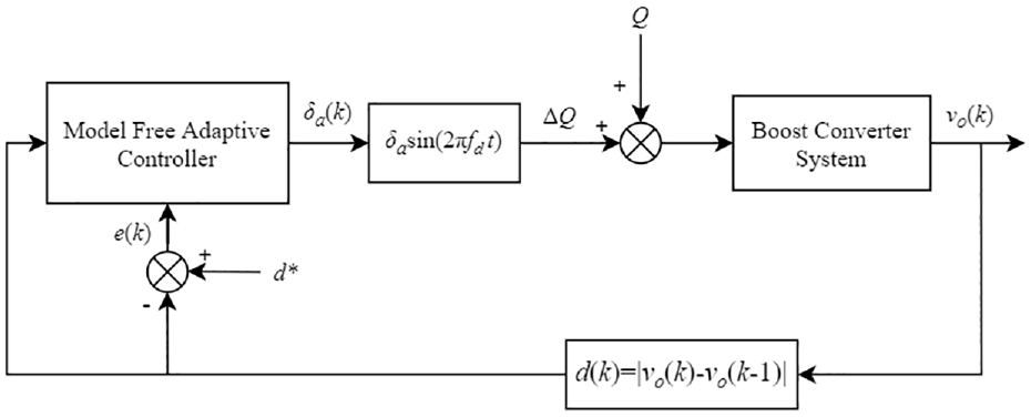
The structure diagram of the control system.
In Figure 6, Q is the circuit parameter that has a great influence on the system and is easy to change; δasin(2πfdt) is the disturbance term (i.e. △Q), δa is the perturbation amplitude (i.e. the output of the model-free adaptive controller), fd is the disturbance frequency (fd is equal to the switching frequency). vo is the output voltage of the system; d is the difference between the output voltages of the system after two adjacent iterations, that is, d(k) = |vo(k)−vo(k−1)|; d* is the expected value of the difference between the output voltages of the system after two adjacent iterations; e(k) is the error between the expected difference and the actual difference between the output voltages of the system after two adjacent iterations, that is, e(k) = d*−d(k).
Controller design
Given the I/O data (discrete time I/O data) of the controlled Boost converter, we can described the system as follows
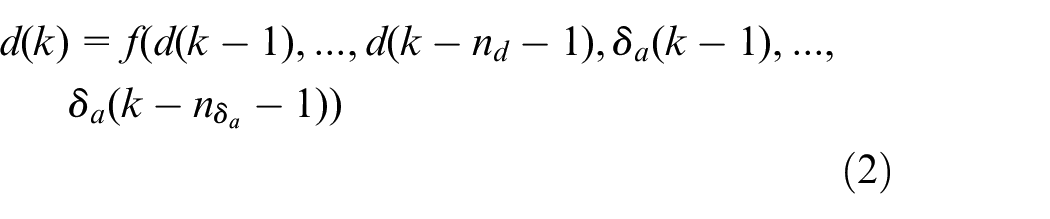
where d(k) is the output of the Boost converter at time k, d(k) = |vo(k)−vo(k−1)|; δa(k) is the input of the Boost converter at time k (i.e. the output of the controller at time k); nd and nδa represent the unknown order of the system respectively; f (·) is an unknown nonlinear function.
The Boost converter system shown in equation (2) satisfies three assumptions: the I/O data of the system is measurable and controllable; the partial derivative of f (·) with respect to the control input signal δa(k) of the system exists and is continuous; The system is generalized Lipschitz, that is to say, for any value of k and Δδa(k) = δa(k)−δa(k−1) ≠ 0, there is

where d(k) represents the distance between two adjacent points on the Poincaré section, which can reflect the trend of the system approaching stable periodic motion (i.e. the difference between the output voltages vo of the system after two adjacent iterations, d(k) = |vo(k)−vo(k−1)|), where vo(k) is the value of the output voltage vo of the system at time k;
Based on equation (3), we consider the control input criterion function as follows
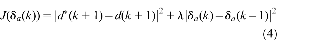
where d* (k + 1) is the expected output (i.e. the expected value of the distance between two adjacent points on the Poincaré section, i.e. the expected difference between the output voltages vo of the system after two adjacent iterations); λ is the weight factor.
By substituting equation (3) into equation (4), the chaotic motion control algorithm of Boost converter can be obtained as follows according to
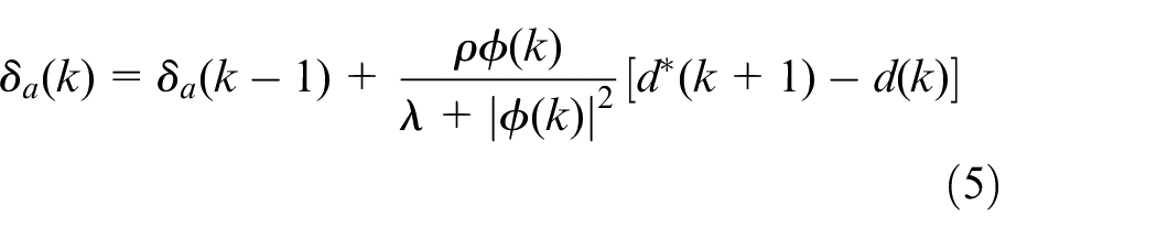
where ρ is the step sequence.
Since
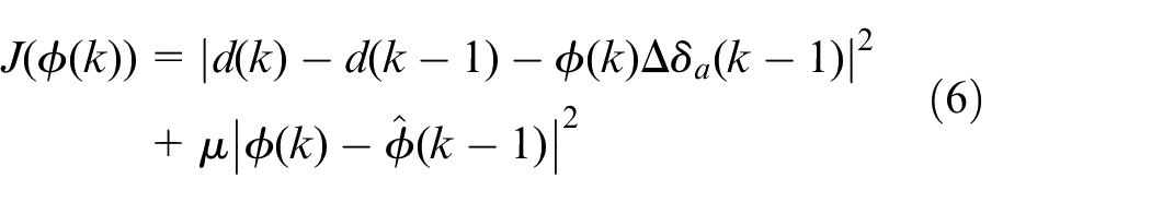
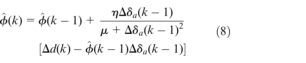
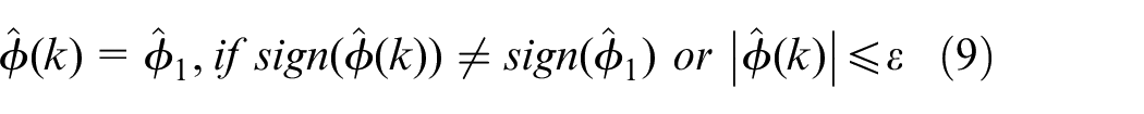
In equation (8), η is the step sequence; μ is the weight coefficient, μ > 0. In equation (9),
In summary, the model-free adaptive chaos controller of the current-mode-controlled Boost converter system can be written as
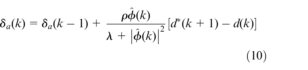
As can be seen from equation (10), the design of the model-free adaptive chaos controller does not depend on the model information and structural information of the system, but is only related to the I/O data of the controlled system. In the control process, only one one-dimensional parameter value (i.e. the estimated value of the PPD) waits to be adjusted online.
In summary, the proposed MFACC method of the Boost converter system only uses the I/O data of the controlled system to design the controller. The perturbation amplitude δa(k) output by the model-free adaptive controller is used to calculate the disturbance quantity (i.e. δasin (2πfdt)). Then the disturbance quantity is applied to the controllable circuit parameter Q to realize the chaotic motion control of Boost converter. The proposed method is not only simple to calculate but also easy to implement.
Simulation research and analysis
Control effects of the chaotic motion
By means of simulation, the proposed MFACC method is used to control the chaotic motion generated in the Boost converter.
It is found that the chaotic motion can be caused by the changes of the input voltage, the inductance, the capacitance, the resistor, the reference current and other parameters in the circuit system. Therefore, a reasonable controller is designed to output a tiny perturbation quantity imposed on one of the above circuit parameters, so that the survival conditions of the chaotic motion change, so that chaos control can be realized. Due to space limitation, this paper considers that the reference current in circuit parameters has a great influence on the system and is easy to change, so only the reference current is selected as the excitation parameter, and Iref is replaced by Iref + δ a sin(2πfd t). Therefore, this paper only shows the effect of the chaos control when the perturbation quantity output by the controller is imposed on the reference current of the system.
In order to compare the effects before and after controlling chaotic motion, the controller starts to exert control on the chaotic motion at the 200th iteration of the system. The input of the system (i.e. the output of the controller) δa = 0 before the control is applied.
Figure 7 richly shows the control effect after adopting MFACC method. During the simulation, according to a large number of tests, the six initial parameters of the controller are set as follows:
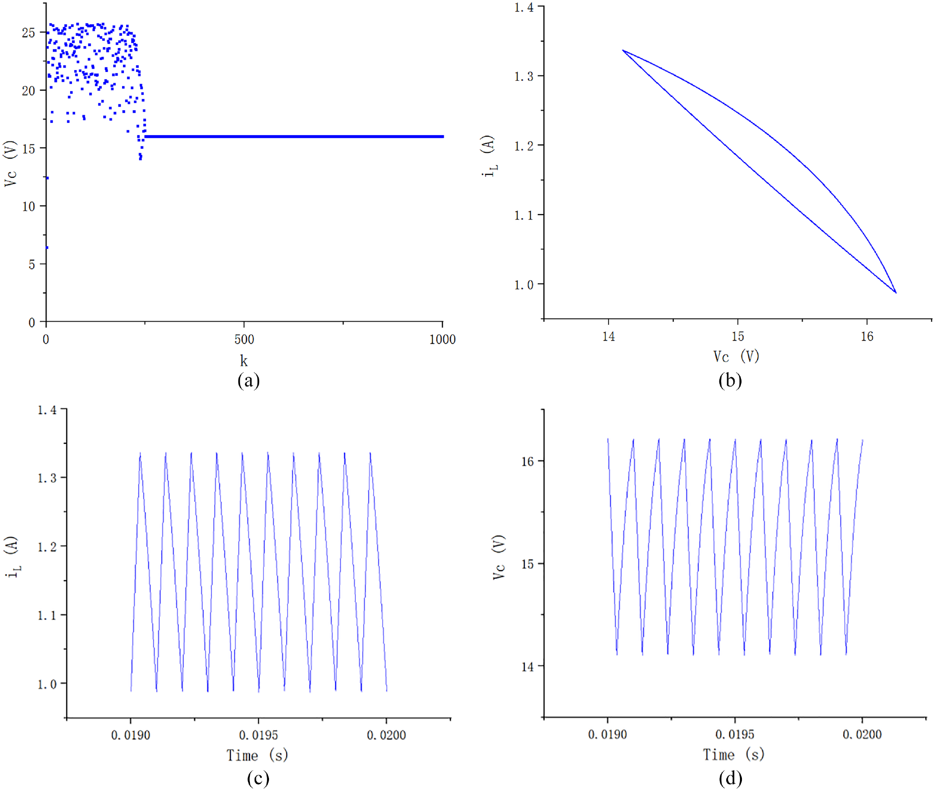
The effect of chaotic motion control of the system (Iref = 1.3369 A). (a) The period-1 orbit of the system after control, (b) the phase portrait of vc−iL, (c) the waveform of iL, and (d) the waveform of vc.
In Figure 7, the chaotic motion can be stabilized quickly (at k = 250) to the orbit of period-1. At this time, the phase portrait is a closed curve. The waveforms of the inductive current and the capacitive voltage both indicate that the system is moving at period-1.
Figure 8 shows the simulation results of chaos control when the corresponding parameters of the controller are set as:
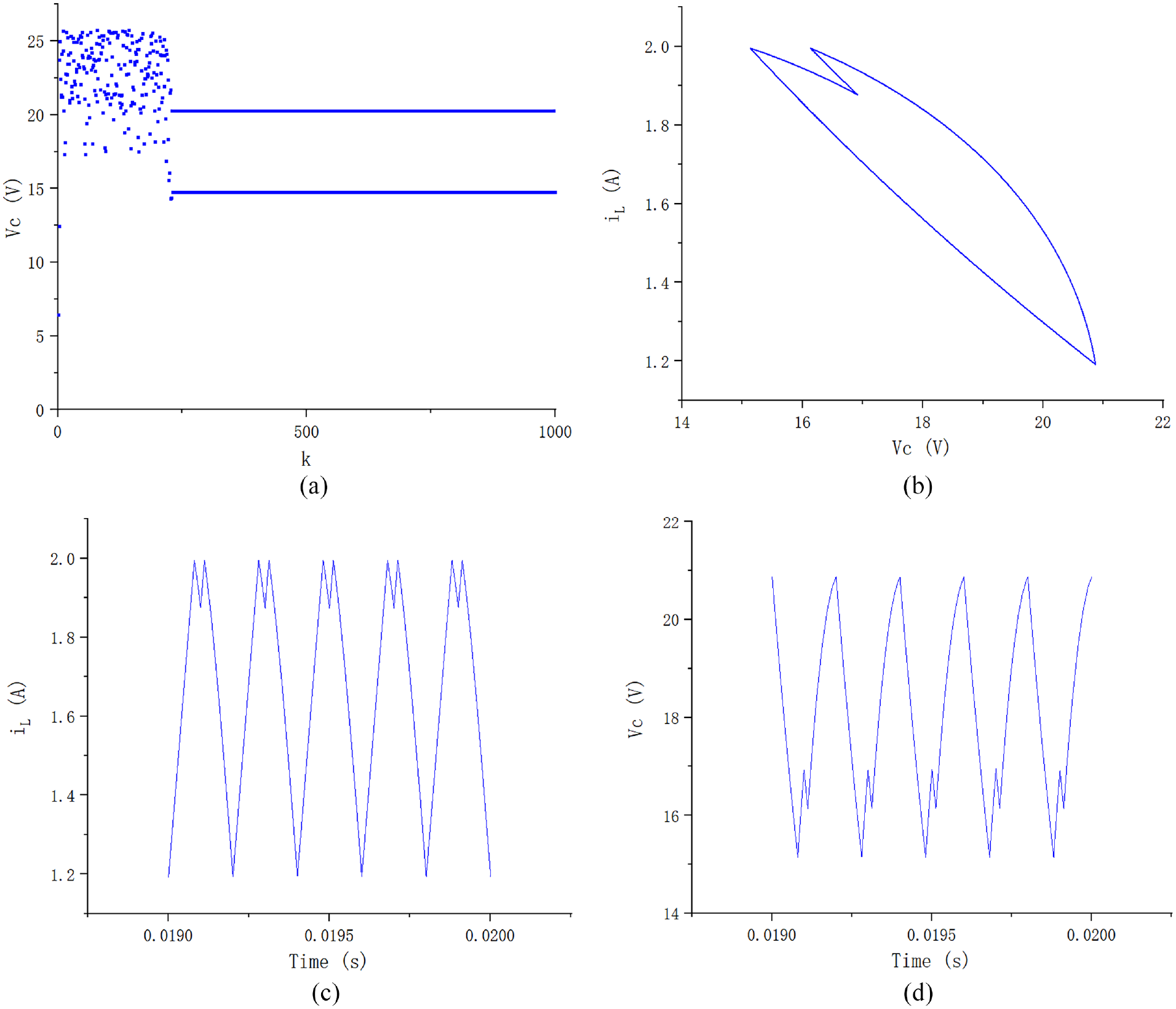
The effect of chaotic motion control of the system (Iref = 1.9954 A). (a) The period-2 orbit of the system after control, (b) the phase portrait of vc−iL, (c) the waveform of iL, and (d) the waveform of vc.
In Figure 8, the chaotic motion can be stabilized quickly (at k = 229) to the orbit of period-2. At this time, the phase portrait has a partial depression compared to the orbit of period-1. The waveforms of the inductive current and the capacitive voltage both indicate that the system is in the period-2 motion.
Through simulation studies, it can be found that the expected targets can also be set as other orbits of period-n when applying the method in this paper to the chaotic motion of the system shown in Figure 1 under the condition that the controller parameters are selected appropriately. However, due to the consideration of space, only the control renderings of orbits of period-1 and period-2 are given here. The control effects of the remaining periodic orbits are not discussed.
It can be seen from the above results that the proposed MFACC method is effective and the control effect is ideal for the chaotic motion control of the current-mode-controlled Boost converter system.
The influence analysis of controller parameters on chaos control effect
The simulation study found that the values of the controller parameters can have an impact on the chaos control effect. In the following, the relationship between different values of controller parameters and the effect of chaos control is analyzed and compared for the case where the expected control target is period-1 motion. The case where the control target is the period-2 motion is similar to the case where the control target is moving in period-1. For the sake of space, it will not be described in this section.
Analysis of influence of single parameter value of controller on chaos control effect
The chaos control of Boost converter is simulated by changing the value of one of the parameters
The influence of single parameter value of controller on chaos control effect.
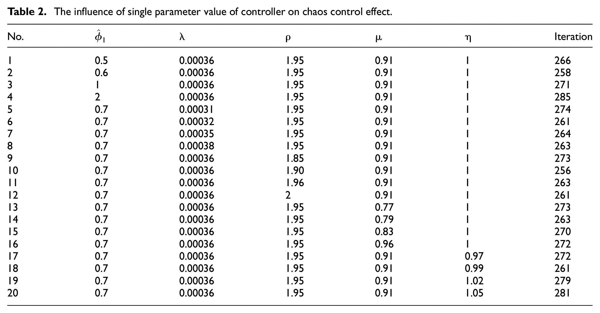
It can be seen from Table 2 that although chaotic motion of Boost converter can be guided to the desired period-1 orbit under each set of parameters, the control effect is different from that in Section 4.1: for example, when
To better evaluate the influence of single parameter value of the controller on the chaos control effect, this section selects part of the simulation experiment results from Table 2 to draw the effect diagram of chaotic motion control of the system. In order to make the figure more clear and intuitive, the selected outcomes are the simulation experiment results with the minimum iteration times of each parameter of the controller (i.e. the fastest control speeds). Five parameters are five simulation experiment results in total. The simulation result in Section 4.1 is added for comparative analysis, and the chaos control effect diagram as shown in Figure 9 is drawn.
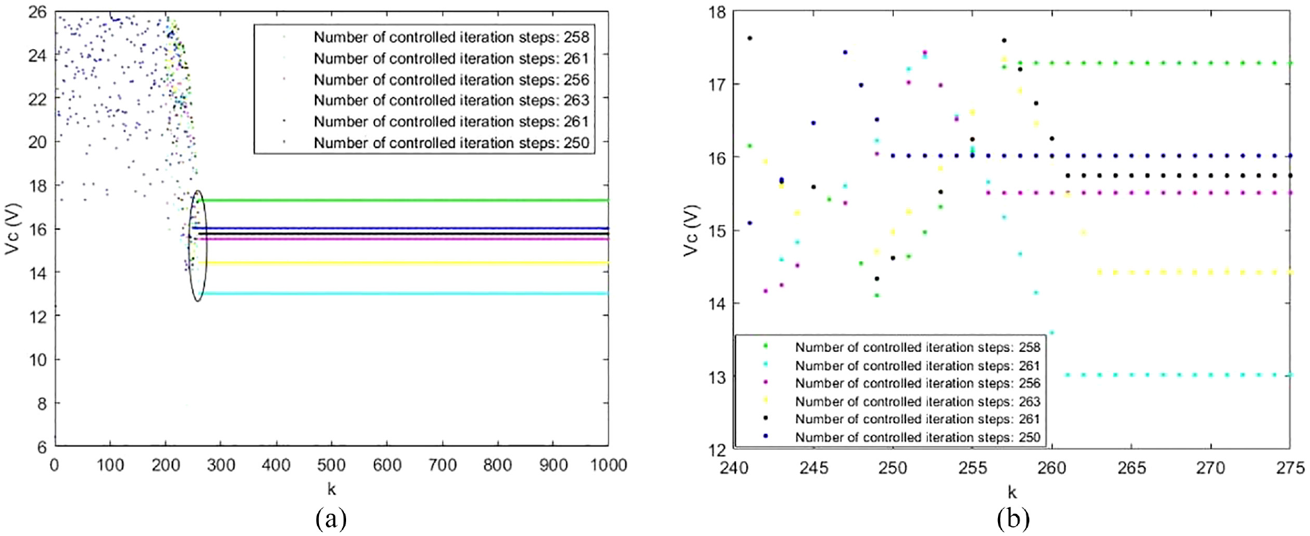
Chaos control effect diagram of single parameter value of the controller: (a) global control effect (range of system iteration: 0–1000) and (b) local control effect (range of system iteration: 240–275).
Figure 9(a) is a global rendering of the control applied to chaotic motion when the system iterates 200 times (the system iterates 1000 times in total). In order to compare and analyze the influence of controller parameters on the speed of chaos control more clearly, the region range of system iteration times from 240 to 275 is marked with an elliptical circle on Figure 9(a), and the local chaos control effect diagram as shown in Figure 9(b) is obtained after enlarging the region. It can be clearly observed from Figure 9 that: when
Evidently, the value of each parameter of the controller will have an impact on the chaos control effect. To obtain a relatively satisfactory control effect, the relatively optimal controller parameter must be selected.
Analysis of the influence of different parameter combinations of the controller on the chaos control effect
Simultaneously changing the values of any three parameters/four parameters/all parameters of the controller (5 simulation experiment results for each case, 15 simulation outcomes in total), the chaotic control effect obtained is analyzed and compared, and the results are shown in Table 3. In Table 3, No.1 to No.5 are the simulation results when three parameters are varied simultaneously; No.6 to No.10 are the simulation results when four parameters are changed at the same time; No.11 to No.15 are the results when all parameters are changed in the meantime. Table 3 shows that different combinations of controller parameters will have corresponding effects on the chaotic control effect of the system. According to the simulation outcomes in Section 4.1, it can be found that only the relatively optimal combination of controller parameters can obtain the relatively optimal control effect.
The influence of different combinations of parameters of the controller on the effect of chaotic control.
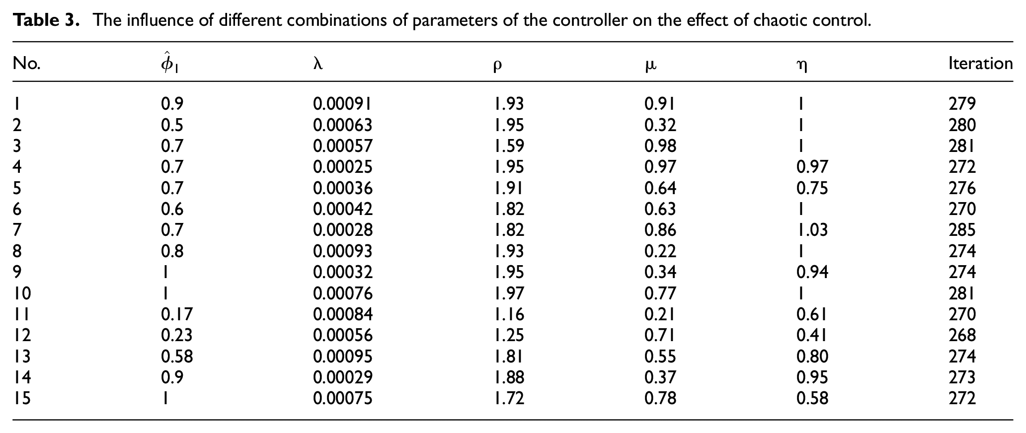
To better evaluate the influence of different parameter combinations of the controller on the control effect and let readers read more clearly, this section selects three groups of parameters corresponding to the fastest chaos control speeds No.4, No.6, and No.12 from No.1 to No.5, No.6 to No.10, No.11 to No.15 in Table 3 respectively. In addition, the parameters in Section 4.1 are added for comparison, and the effect diagram of the chaotic motion control of the system as shown in Figure 10 is drawn. In Figure 10, green, cyan and magenta are respectively used to show the chaos control effect under the corresponding parameters of No.4, No.6, and No.12. Draw the control effect under the parameters in Section 4.1 in blue. The comparative analysis process is similar to that in Section 4.2.1. Due to limited space, it will not be repeated in this section.
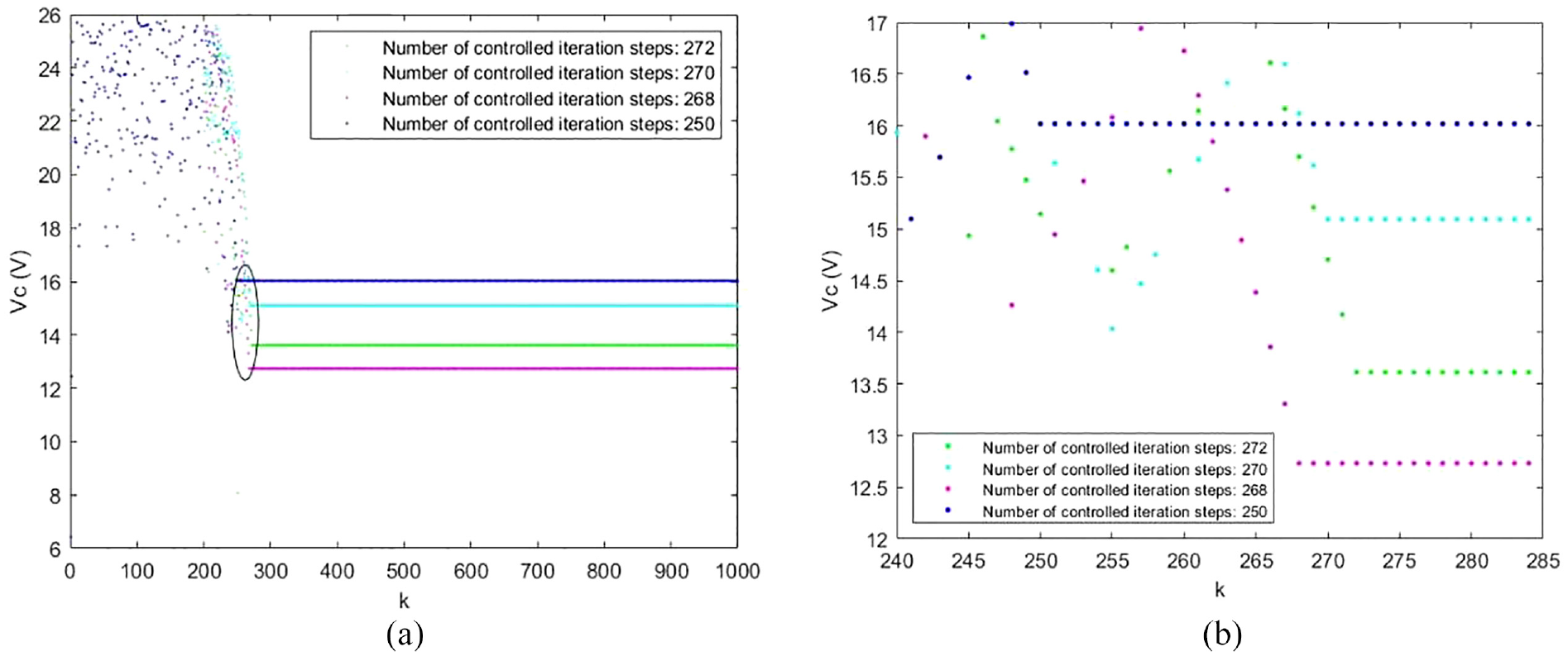
Chaos control effect diagram of different parameter combinations of the controller: (a) global control effect (range of system iteration: 0–1000) and (b) local control effect (range of system iteration: 240–285).
To sum up, not only the change of a certain parameter in the controller will affect the chaos control effect, but also the simultaneous change of multiple parameter values of the controller will affect the chaos control effect. Only by selecting the relatively optimal combination of controller parameters can the relatively optimal control effect be obtained. It can be seen that the chaotic motion of Boost converter can be effectively controlled by using the proposed method as long as the controller parameters are properly selected.
Conclusions
In this paper, a MFACC method of the Boost converter system is proposed by taking advantage of the advantages that the MFAC method does not depend on the PMM of the system and only uses the I/O data of the system to design the controller. The method achieves the purpose of guiding the chaotic motion of the system to periodic orbit. The simulation results show that the controller designed in this paper can meet the control requirements well. The controller quickly makes the system search automatically and finally stabilizes it in the expected periodic orbit. In addition, reasonable selection of the controller parameters is the guarantee of good control quality. The research results of this paper provide a new idea and method to solve the control problems of chaotic motion of Boost converter in engineering practice.
In the future, in order to further improve the design efficiency of the controller, the next step is to carry out the corresponding research on chaos control of DC-DC converter system by combining intelligent optimization algorithm and MFAC, expecting to obtain the corresponding research results in the construction of control performance index function and optimization algorithm configuration.
Footnotes
Declaration of conflicting interests
The author(s) declared no potential conflicts of interest with respect to the research, authorship, and/or publication of this article.
Funding
The author(s) disclosed receipt of the following financial support for the research, authorship, and/or publication of this article: This work is supported by National Natural Science Foundation of China (Grant No. 51665027), Youth Science and Technology Fund program of Gansu Province (Grant No. 21JR7RA328), Introduction of talents research launch project of Shanghai Institute of Technology (Grant No. YJ2021-18 and YJ2021-19). Collaborative Innovation Fund Project of Shanghai Institute of Technology (XTCX2023-20).