
Abstract
According to the unstable and nonlinear performances of the servo valve-controlled hydraulic motor, classical control methods based on linear theory are gradually unable to meet the high-performance requirements of the system. Using the servo valve-controlled hydraulic motor based on the third-order active disturbance rejection control (ADRC) to improve the dynamic performance of the system is feasible. The mathematical model and the simulation model of the third-order ADRC for the servo valve-controlled hydraulic motor system are established respectively. For the phase lag caused by the third-order ADRC controller, the control performance of the ADRC controller is significantly improved using the advance forecast. The simulation experiment results show that the designed ADRC controller has good tracking performance and stronger robustness of the system than the traditional PID controller.
Introduction
The electro-hydraulic servo system has outstanding characteristics such as large output torque, high power-to-weight ratio, fast response and strong anti-load capability, making it widely employed in numerous significant fields, 1 such as excavators, 2 hydraulic load simulators,3,4 and industrial robots. 5 As one of the commonly used hydraulic power mechanisms, the servo valve-controlled hydraulic motor has the characteristics of large torque, wide-range stepless speed regulation, and good safety. It is mainly used in construction machinery, metallurgical machinery, and marine machinery. When the servo valve-controlled hydraulic motor develops in the direction of high precision, high frequency response, and strong anti-disturbance ability, the classical control method based on linear theory gradually cannot meet the high performance requirements of the system. Therefore, more advanced nonlinear control methods must be studied for the electro-hydraulic system of servo valve-controlled motors. 6 In response to the above problems, Han and Wang pointed out a series of shortcomings of traditional PID control and carried forward and enriched the essence of PID control thought (“Eliminate errors based on errors”). Arrange the “transition process” to extract the “differential” reasonably, propose a nonlinear tracking differentiator (TD), 7 and give the discrete form of the TD. 8 The linear error feedback rate 9 is combined into a novel Active Disturbance Rejection Control (ADRC). 10 Due to the large number of adjustable parameters of ADRC controller, which limits its application in practical control engineering, 11 Han obtained a linear extended state observer parameter sequence closely related to the Fibonacci sequence through a large number of simulations. Gao introduced the concept of bandwidth and proposed a linear ADRC controller, 12 which brought great convenience to the parameter tuning of the linear ADRC controller. At present, ADRC controller has been successfully used in a large number of engineering control practices, and has been initially commercialized, 13 such as ADRC controller is used for flight attitude control, 14 rock drilling robot combined with hydraulic drive control, 15 Antenna anti-wind interference servo system, 16 and so on. Zhang and Cao took the pump-motor system as the research object and proposed a fuzzy linear ADRC controller. 17 Hu and Li 18 proposed an improved linear ADRC controller for valve-controlled hydraulic motors, which reduced chattering. Carpio-Alemán et al., 19 realized linear PID speed and position control with adaptive coefficients, allowing valve-controlled hydraulic motors to reconfigure PID parameters when the working point changes. Zheng et al. 20 proposed a synovial variable structure controller for a variable displacement hydraulic motor system on a constant pressure network, which has a faster response speed and is insensitive to parameter changes or external disturbances. However, some of the above research works have gradually failed to meet the requirements of high-performance electro-hydraulic servo systems under the previous linear control strategies. In order to reduce the influence of model uncertainty and nonlinear characteristics in electro-hydraulic servo systems, other nonlinear control schemes are proposed, such as disturbance observer,21–24 state observer,25–27 and adaptive control.28,29
This paper presents a mathematical model for the servo valve-controlled hydraulic motor and establishes an active disturbance rejection controller for it. The paper analyzes the phase lag phenomenon caused by the controller and introduces an advanced forecasting link to improve its performance. Simulation experiments demonstrate that the tracking performance of the ADRC controller with the advanced forecast link is superior to that of the general form of the ADRC controller. In addition, this study compares the anti-disturbance abilities of ADRC and PID controllers using input disturbances such as white noise and sinusoidal disturbance. The results show that ADRC exhibits good tracking performance and strong robustness. In conclusion, this study highlights the potential of ADRC in enhancing the performance of servo valve-controlled hydraulic motors.
The mathematic model of servo valve-controlled hydraulic motor system
The schematic diagram of servo valve-controlled hydraulic motor system is shown in Figure 1.
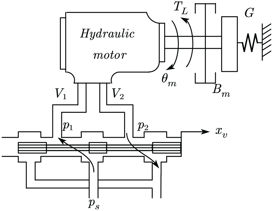
Servo valve-controlled hydraulic motor system.
The flow-pressure characteristic equation of the servo valve is:

Where
The hydraulic motor flow continuity equation is:
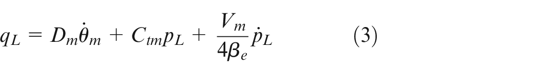
Where
The hydraulic motor load torque balance equation is:

Where
The bandwidth of the electro-hydraulic servo valve is much larger than that of the valve-controlled hydraulic motor system. Therefore, the control voltage of the electro-hydraulic servo valve and the displacement of the servo valve can be assumed to have a proportional relationship, which can be expressed as follows:

The external load of the servo valve-controlled hydraulic motor system is mostly inertial load.
30
This means that the torsional rigidity of springs
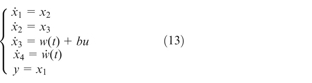
Write the nonlinear equation of the system as the state equation, and select the angular displacement, angular velocity and angular acceleration as the system state vector, then the state vector can be written as:

The entire system, (1)–(6), can be obtained in the state equation form as:
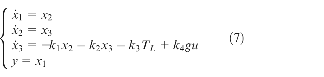
Where
Design of the ADRC controller
For a class of high-order uncertain nonlinear systems, the conventional ADRC scheme involves a tracking differentiator (TD), an extended state observer (ESO), and nonlinear state error feedback law. The third-order controller of ADRC is shown in Figure 2.
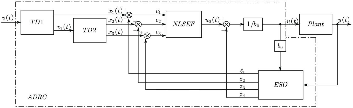
Third-order ADRC controller.
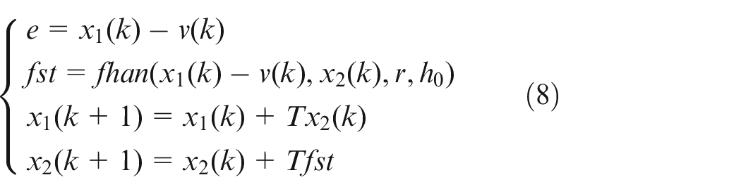
Tracking differentiator (TD)
According to the literature,7,8 its nonlinear TD is designed as:
Where the time-optimal comprehensive function
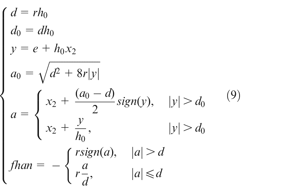
Where parameter
The TD can process the measurement signal to any order of tracking in theory. But the second-order TD is generally used to process the tracking of the noisy signal and the first-order differential extraction in practice. So the

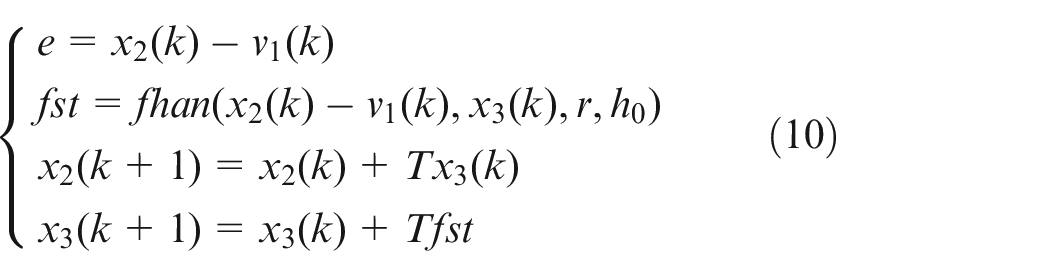
Where
So far, the three required signals
Extended state observer(ESO)
The ESO is the core part of the ADRC controller. Its core idea is to account for uncertain factors which include unmodeled dynamics within the system, external disturbances, and complex nonlinear factors that are not easily managed by traditional control methods. These factors are collectively referred to as the “total disturbance” of the system. By constructing an ESO using the input and output of the system, the “total disturbance” can be estimated online and compensated for in the feedback control link.
The design of state observers in linear system theory often assumes that the internal dynamics of the system be known. But this is not in line with engineering practice. However, this assumption does not align with engineering practice, it is a strong assumption that the parameters are completely known. 6 Considering the unmodeled state except u and its internal disturbance in equation (7), the external disturbance is defined as a nonlinear function:

Expand the real-time action of

Then system (7) expands into a new control system:
According to Han, 31 an ESO is established for this expanded system, and its discretization algorithm is:
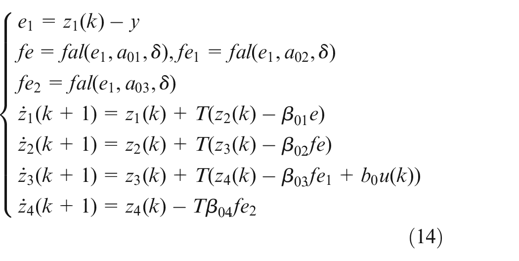
Where
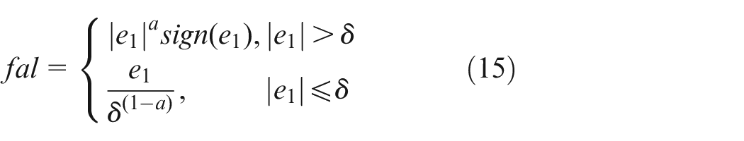
Different from the classical PID’s “large error, large gain; small error, small gain,” when
Where the parameter
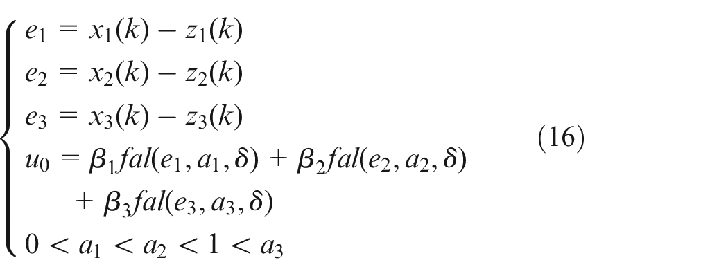
Nonlinear State Error Feedback Law (NLSEF)
After completing the TD and the ESO, we can utilize the error and its differential to carry out nonlinear combination, and form a NLSEF with the compensation amount for the total disturbance in the ESO 5 :
According to the literature,
30
where
The final control law of the system is designed as:
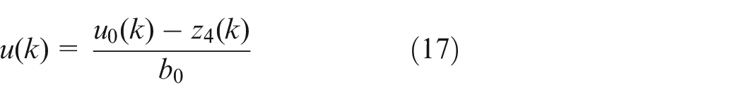
At this point, the ADRC controller has been established. Its schematic diagram based on the third-order active disturbance rejection control system is shown in Figure 3.
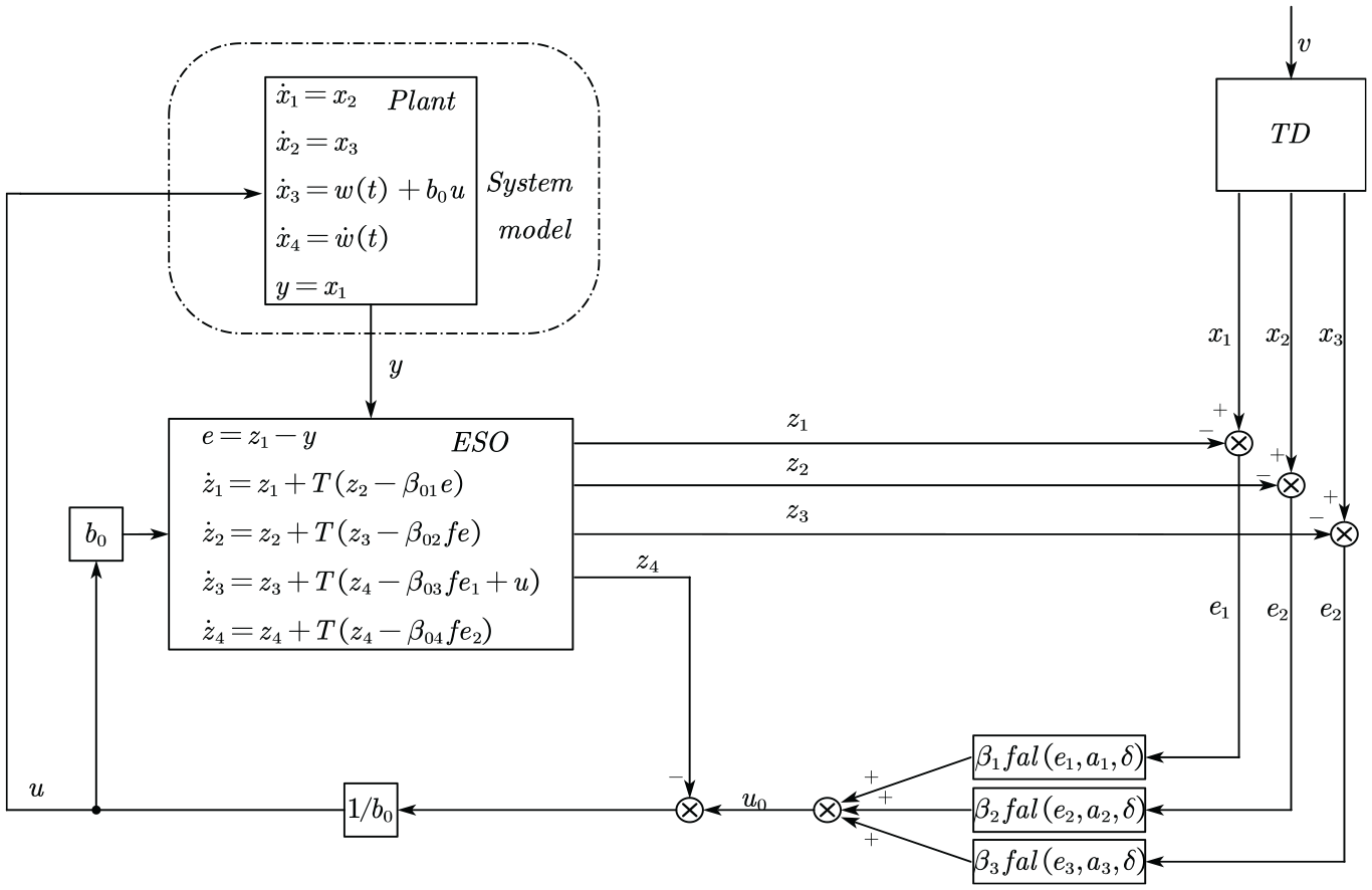
Control system based on the third-order ADRC.
Advance forecast
When using the TD to reasonably extract the differential signal or extract the differential signal polluted by noise, it is equivalent to performing a filtering process. However the filtered signal will produce a certain phase lag. To compensate for this phase loss, using the differential signal given by the TD to carry out appropriate forecast correction can lead to favorable outcomes. 32
In the paper, the authors employ the “differentiation first, prediction later” method to mitigate phase loss. The algorithm is as follows:
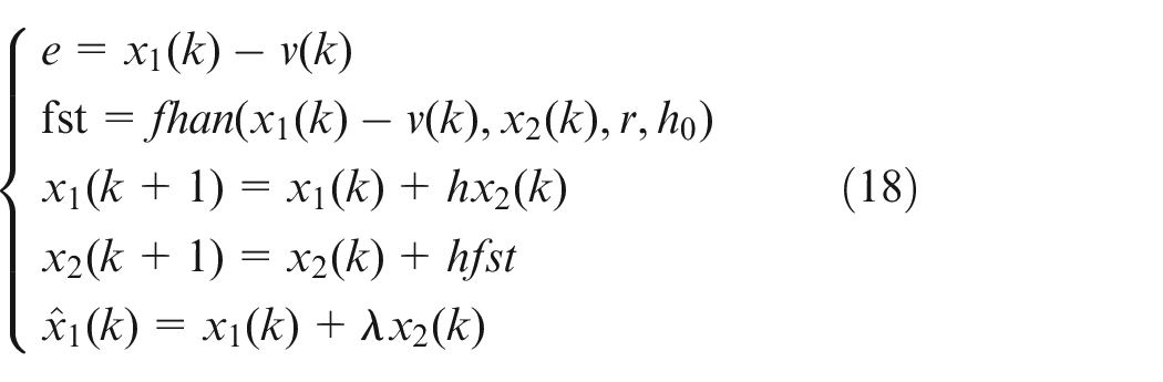
Where
The improved TD diagram is shown in Figure 4. Two TDs are needed in this paper, and the same way can also be used for advance prediction.
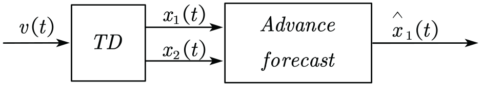
Advance forecast tracking differentiator.
Simulation experiment analysis
Simulation model
In order to verify the effectiveness of the ADRC algorithm, In this study, we used MATLAB/Simulink software for simulation, employing the ode45 algorithm with a step size of
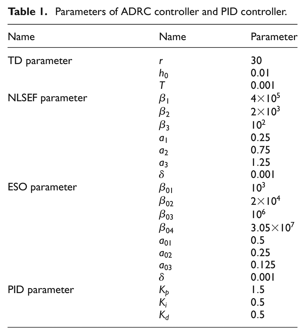
Parameters of ADRC controller and PID controller.
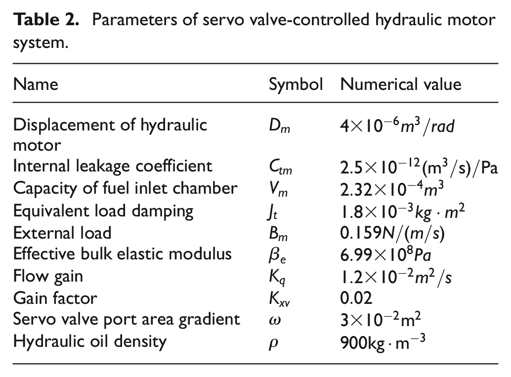
Parameters of servo valve-controlled hydraulic motor system.
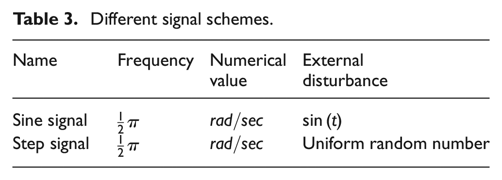
Different signal schemes.
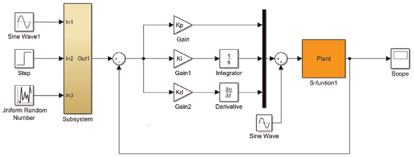
Simulation model of PID.
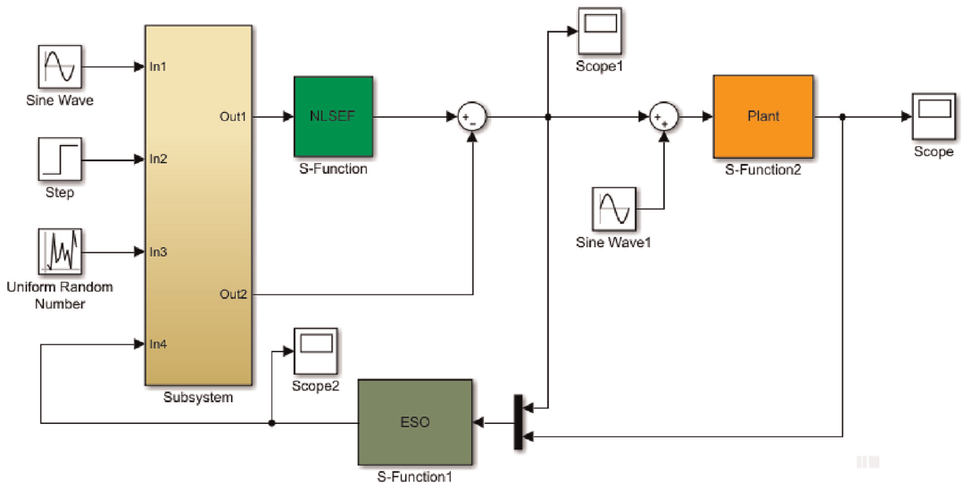
Simulation model of ADRC.
Basic performance comparison
Figures 7 and 8 illustrate the angular displacement tracking performance and tracking error of the ADRC controller and the ADRC controller with advance prediction, respectively, when applied to the servo valve-controlled hydraulic motor under a sinusoidal signal response. The results show that the ADRC controller with advanced prediction reduces oscillation from 0 to 0.3 s, which leads to a faster time to reach a stable state compared to the ADRC controller without advanced prediction.
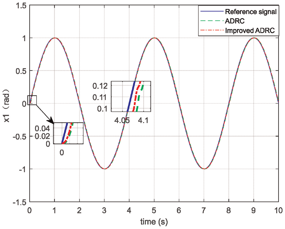
Angular displacement tracking performance.
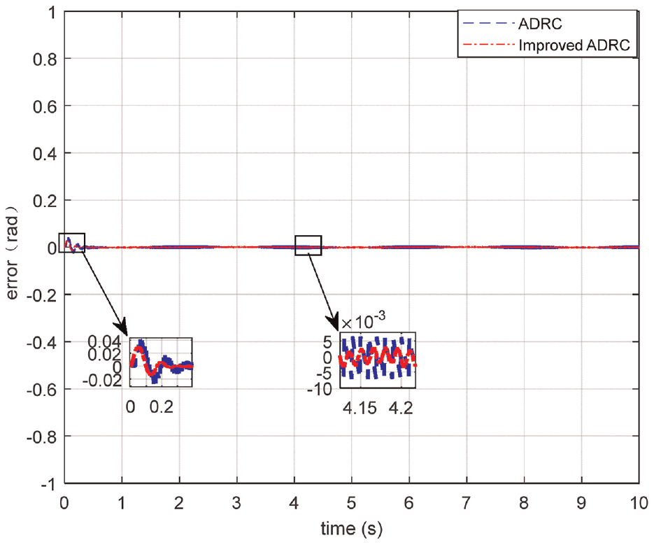
Angular displacement tracking error.
The author uses the average tracking error as a metric to assess the effectiveness of the two controllers, where the average tracking error is defined as follows:
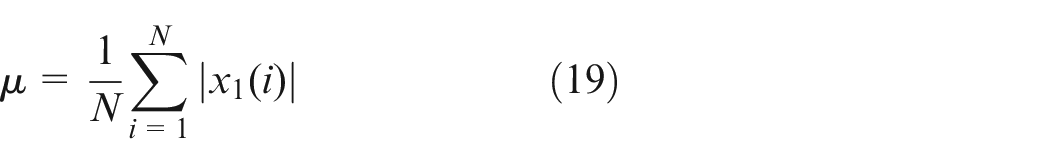
The average tracking error of the general ADRC controller, calculated by formula (19), is
Figures 9 and 10 show the uncompensated and disturbance-compensated control laws, respectively, when subjected to sinusoidal signals. The control laws employ the extended state observer to estimate and counteract real-time disturbances, thereby linearizing the original system. After the disturbance compensation, the closed-loop system transforms into an integral series type. The figures demonstrate that the control law has significantly improved after compensation.
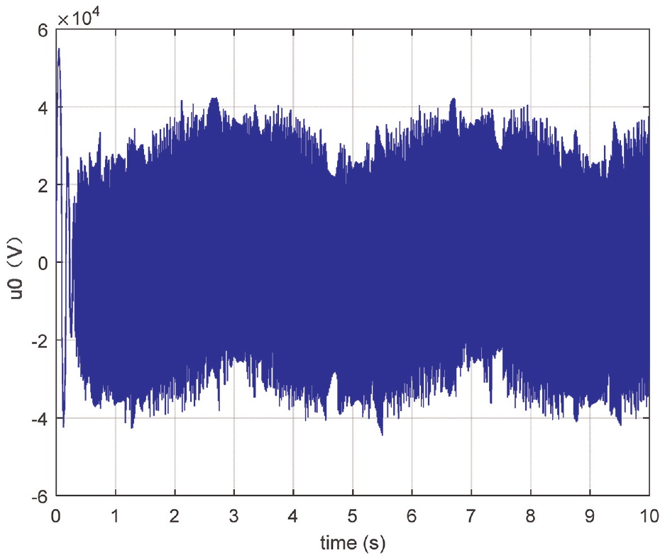
Uncompensated control law using improved ADRC.
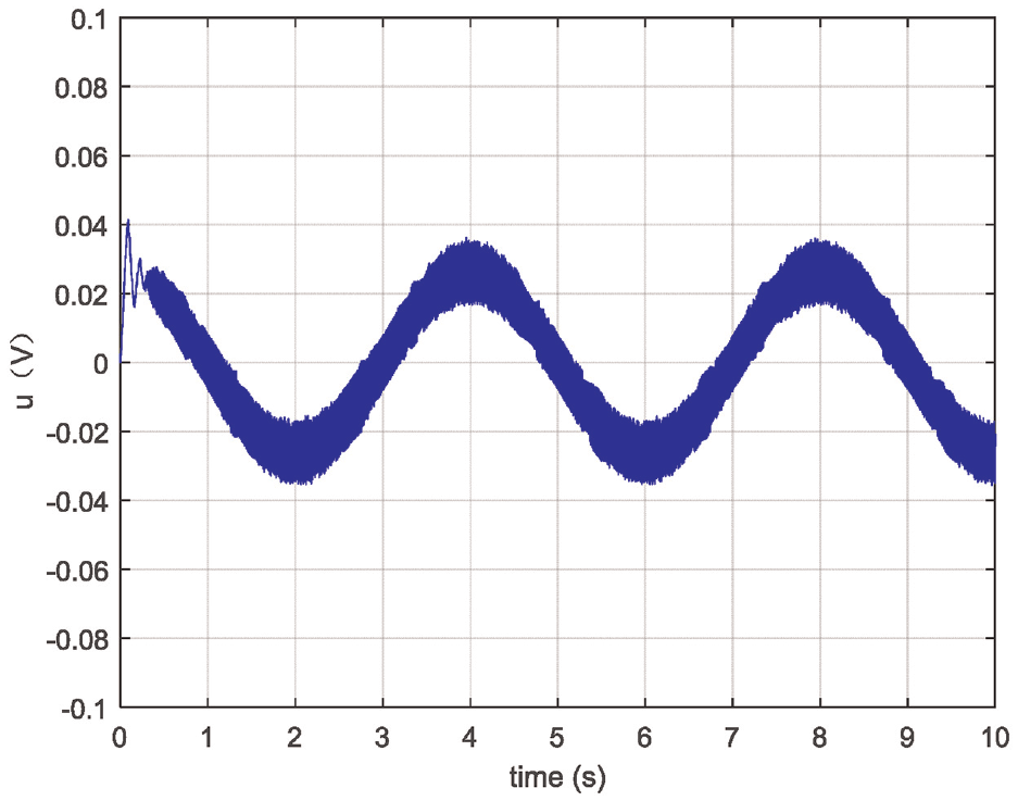
Compensated control law using improved ADRC.
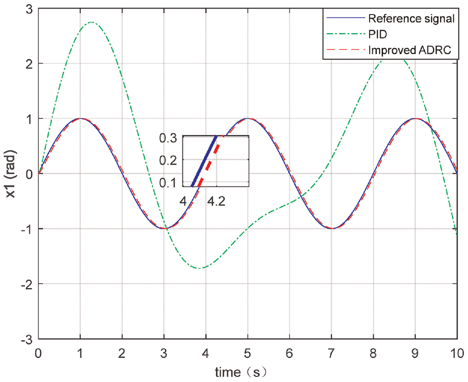
Under the sinusoidal signal, Figures 11 and 12 demonstrate the angular displacement tracking performance and error for both the traditional PID controller and the ADRC controller with advance prediction. The figures clearly demonstrate that the improved ADRC controller has a better control effect than the traditional PID controller, and enters a stable state faster. It can be seen from the simulation experiment that the improved ADRC controller has excellent control effect, which enables the system to track the target signal more quickly and smoothly without overshoot.
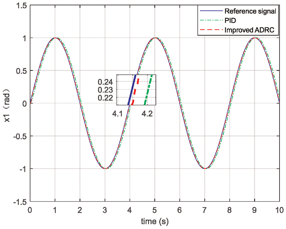
Angular displacement tracking performance.
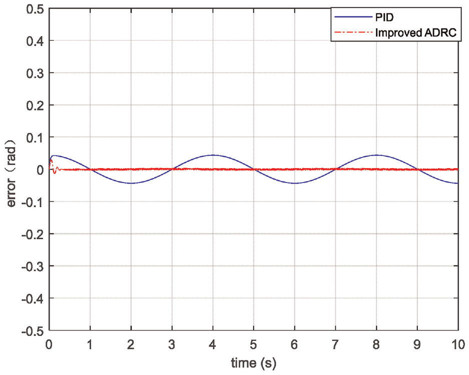
Angular displacement tracking error.
Based on formula (19), the average tracking error for PID control is
Keep controller parameters unchanged, and input sinusoidal disturbance with amplitude of 1.
The results presented in Figures 13 and 14 indicate a notable decrease in the effectiveness of PID in tracking the desired signal under sinusoidal disturbance, whereas ADRC demonstrates accurate tracking performance even under such conditions. Moreover, Figure 14 illustrates that z4 represents the estimated disturbance value obtained by ESO, while fx represents the actual disturbance output by the controlled object. This figure emphasizes that ADRC can perform online real-time disturbance estimation and compensation, showcasing its robustness.
Angular displacement tracking error with sinusoidal disturbance.
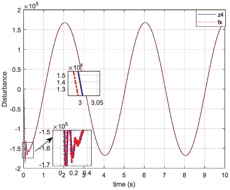
Disturbance.
Anti-disturbance ability comparison
Input step signal to the system accompanied by white noise with an average amplitude of [−0.2, 0.2].
Figure 15 demonstrates that the phase lag of ADRC has been moderately improved through advanced prediction techniques. Figures 15 to 18 are the angular displacement tracking performance and angular displacement tracking error of the ADRC controller with advance prediction and the traditional PID controller under the step response accompanied by white noise, respectively. The figure illustrates that the improved ADRC controller has excellent anti- disturbance ability. The system can achieve stable tracking of signals polluted by noise without overshoot, and can ensure that the steady-state error is less than 0.005, while the control effect of the PID controller introducing noise signals is greatly reduced.
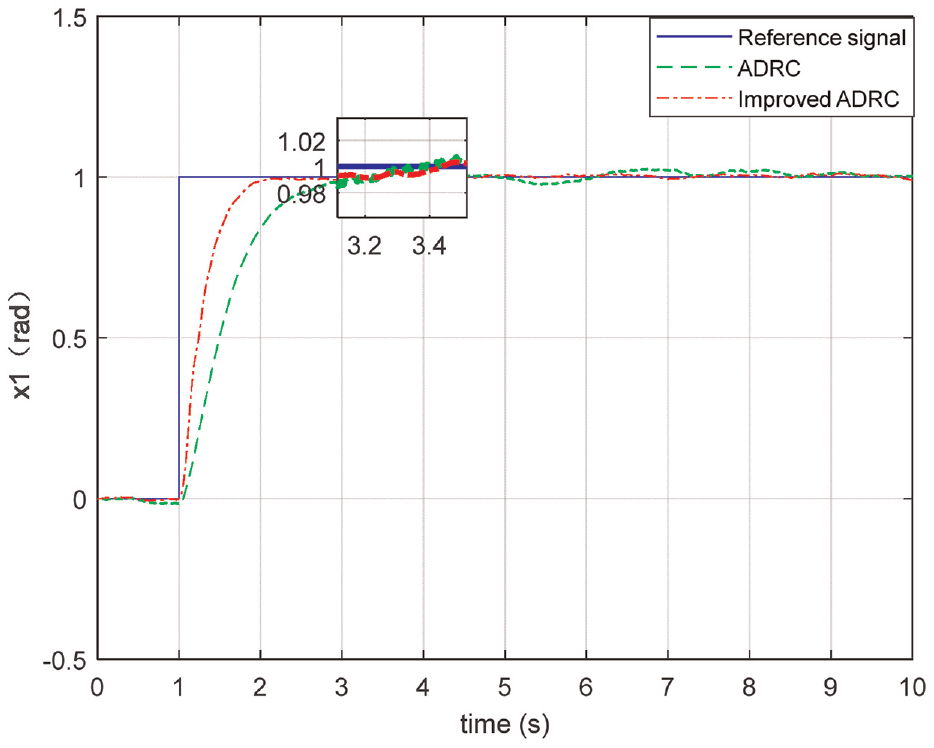
Angular displacement tracking performance.
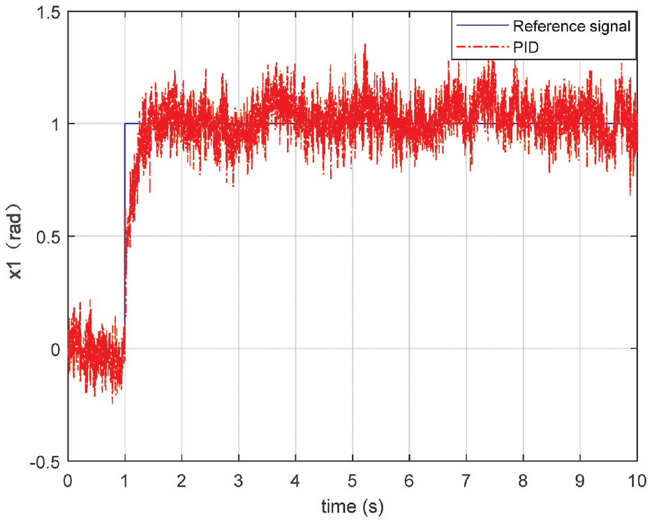
Angular displacement tracking performance using PID.
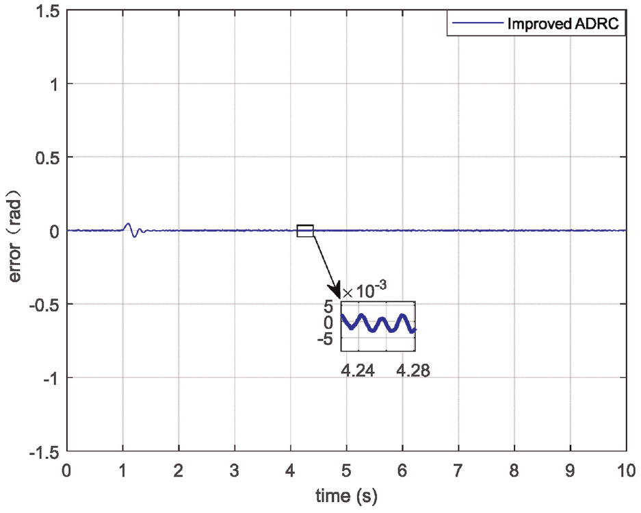
Angular displacement tracking error using improved ADRC.
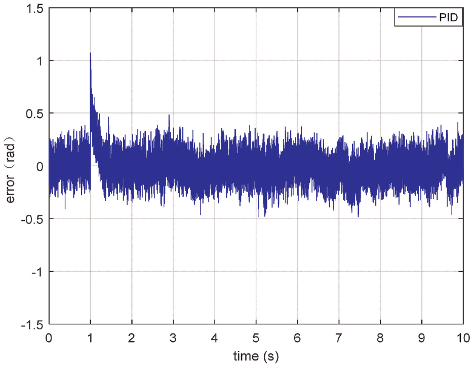
Angular displacement tracking error using PID.
From formula (19), the average tracking error for PID control is
Under the step signal, Figures 19 and 20 depict a schematic diagram of the control variable before and after compensation. The principle is the same as Figures 7 and 8. Through this compensation, we can obtain a relatively good control variable without the influence of the integral term.
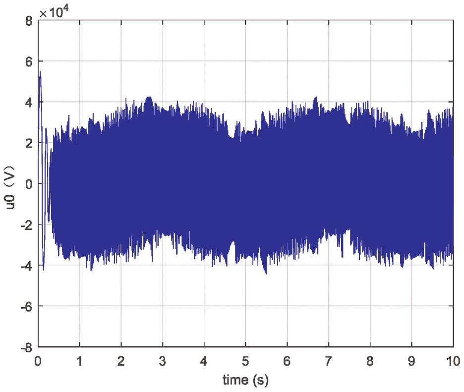
Uncompensated control law using improved ADRC.
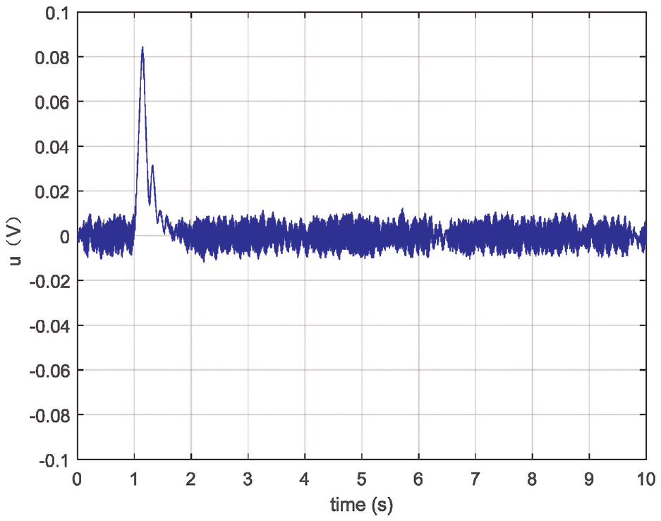
Compensated control law using improved ADRC.
However, the ADRC controller is slightly less rapid in its step, which is due to the phase lag caused by the TD and the ESO filter in the ADRC controller. The arrangement “transition process” emphasized in the TD is to extract the differential signal reasonably in the actual system, that is, to make a trade-off between the effect of the differential and the suppression of noise. The balance point is accepted that both phase lag and noise.
Figure 21 illustrates that z4 is the disturbance estimated by ESO, while fx represents the actual disturbance output by the controlled object. Despite the presence of noise, ESO is able to accurately estimate and compensate for the disturbance in real time, demonstrating its strong robustness.
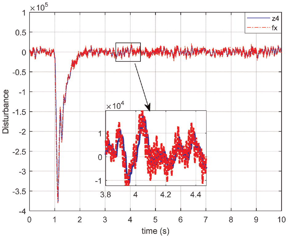
Disturbance.
Conclusions
In this study, a mathematical model for a hydraulic motor system controlled by a servo valve was presented, and the ADRC was proposed as a solution to estimate and compensate for uncertain factors in real-time. The introduction of advance forecasting was used to address the phase lag issue caused by ADRC. Simulation experiments were conducted to evaluate the performance of the ADRC controller with advance forecasting, and the results showed that it outperformed both the general form of ADRC and the traditional PID controller in terms of tracking performance. Additionally, the results demonstrated the effectiveness of ADRC in estimating and compensating for disturbances caused by white noise with an average amplitude of 0.2 and sinusoidal disturbance with an amplitude of 1. Overall, the study provides valuable insights into the application of ADRC in hydraulic motor systems and highlights the potential benefits of using advance forecasting to enhance its performance
Footnotes
Declaration of conflicting interests
The author(s) declared no potential conflicts of interest with respect to the research, authorship, and/or publication of this article.
Funding
The author(s) disclosed receipt of the following financial support for the research, authorship, and/or publication of this article: This work was supported by the Introduced Talents Foundation of Kunming University of Science and Technology (no. KKSY201901014).