
Abstract
Suspension chopper is a high-power electrical equipment which controls the suspension state of maglev train. Its performance directly determines the stability and safety of maglev train. However, the traditional suspension chopper has the problem of high voltage spikes of IGBT and load, which poses a threat to the safe operation of high-speed maglev train. In order to solve this problem, this paper designs a phase-shifted full-bridge suspension chopper, which only adds an auxiliary circuit and four parallel capacitors. The soft-switch is realized by using the phase-shifted control signals, so as to reduce the voltage spikes. Compared with other voltage spike suppression methods, the method has the advantages of good suppression of voltage spikes, simple circuit structure, less use of components, and insensitive to component parameters. The performance of the designed circuit is simulated by ANSYS Simplorer, and verified by experimental test platform. The simulation and experimental results show that the phase-shifted full-bridge suspension chopper can greatly reduce voltage spikes of the load and IGBT.
Introduction
Maglev train is a new rail transportation tool that uses electromagnetic force to realize the active suspension of the train, and gets rid of the adhesion limitation, noise vibration, and rail wear of the traditional wheel-rail train. It has the advantages of high speed, safety, reliability, low maintenance cost, and green environmental protection.1,2 Suspension chopper is a high-power electrical equipment for vehicle suspension control, and its performance is crucial to the stability, reliability, and comfort of maglev vehicles.
At present, the practical suspension chopper mostly adopts hard-switch mode and IGBT switch tubes, which has the problems of large energy loss, large electromagnetic radiation, and high voltage spikes of load and IGBT. In order to improve the performance of suspension chopper, Wang et al. 3 designed a three-level double magnet system, Xiangyu et al. 4 designed an asymmetric three-level suspension chopper, and concluded that the three-level method can reduce the static ripple of the load current and improve the control accuracy. Huang 5 and Shi 6 designed the synovial control strategy and auto disturbance rejection control strategy respectively, which improved the response speed of the load current and the anti-interference ability of the system. Li et al., 7 Xu et al., 8 and Chen et al. 9 studied the application of PWM soft-switch in suspension chopper. By adding the auxiliary switch tube and the resonant circuit, the soft-switch is realized, which reduces the switching loss and electromagnetic radiation. Long et al. 10 designed high temperature superconducting hybrid maglev system, and Wenlong 11 designed permanent magnet hybrid maglev system to replace the electromagnetic maglev system, greatly reducing the energy loss of the load electromagnet.
However, there are few studies on the problem of high voltage spikes of load and IGBT. Weifeng 12 pointed out that the zero-voltage PWM soft-switch technology can suppress the voltage spike problem to a certain extent. But the suppression effect of this circuit is not ideal, because the added auxiliary switch tube adopts the hard-switch mode and the added resonant circuit will increase the voltage oscillation. In the engineering practice of low-speed maglev train, the impact of voltage spikes are generally mitigated by absorbing resistance capacitance diode(RCD) circuit absorption or using redundant hardware devices. But the voltage spikes in high-speed maglev trains are large due to the high supply voltage, which makes the previous method unsatisfactory and the switching energy loss increases rapidly. So it is necessary to study new circuit topologies in order to find a method that can meet the control requirements and effectively suppress the voltage spikes.
The suspension chopper is a converter in essence, which has been researched a lot on the circuit structure, control mode and voltage spike suppression. Köse and Aydemir 13 described the performance of full-bridge push-pull series power converter. The experimental results show that it is superior to diode dropper method and floating boost charger in protecting load, and superior to two-switch buck-boost converter in efficiency and dynamic response. Darvish Falehi 14 and Salari and Darvish Falehi 15 designed an asymmetric multi-level structure, which can generate a high step sinusoidal voltage by using few components. This method improves the stability of power transmission and reduces the cost. Paul Raj and Meenakshi Sundaram 16 proposed a single-phase cascaded H-bridge five-level inverter, which uses sinusoidal pulse width modulation technology to eliminate harmonic distortion. The system has the advantages of high power, high voltage capacity, low harmonics and low switching loss. Liu et al. 17 proposed a voltage spike suppression scheme that optimizes the laminated busbar structure and the absorption capacitor. The experimental results show that the scheme can suppress the voltage spike at about 60% before optimization. Tingting et al. 18 proposed an improved Y-source inverter, which introduced an absorption loop to optimize the topology, effectively improved the input current characteristics and reduced the bus voltage spike. Hongqi et al. 19 proposed a method of incorporating an improved RCD clamping link into the bus of converter, which can effectively control the voltage peak without affecting the performance of system. However, applying the above research results to the suspension chopper will make the circuit structure complicated, which is not conducive to maintaining the requirements of simple and high reliability of the suspension chopper.
Since the phase-shifted full-bridge (PSFB) soft-switch converter was proposed, it has been rapidly developed and applied in occasions with high power, large output voltage and current changes because of its simple structure, convenient control and low power consumption. In this paper, combined with the working principle of the PSFB soft-switch converter and the characteristics of the suspension chopper, the PSFB suspension chopper is proposed. Aiming at the problems of narrow range of zero-voltage conditions and serious loss of duty cycle, an auxiliary circuit is designed to effectively suppress the voltage spikes, which provides a reference for improving the suspension chopper in engineering applications. Simulation and experimental results verify the ability of the circuit.
This paper has been organized as follows: After the introduction of the Section I and Section II analyzes the principle of PSFB suspension chopper in detail and the method of circuit parameters design. In Section III, the simulation and experimental verification of the designed circuit are carried out. The conclusion and final comments are shown in Section IV.
Design of PSFB suspension chopper
Principle of hard-switch suspension chopper
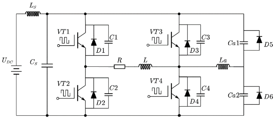
The load current of suspension chopper changes according to the control signals, thereby adjusting the electromagnetic force to stabilize the maglev train. The main circuit diagram of traditional suspension chopper is shown in Figure 1, where
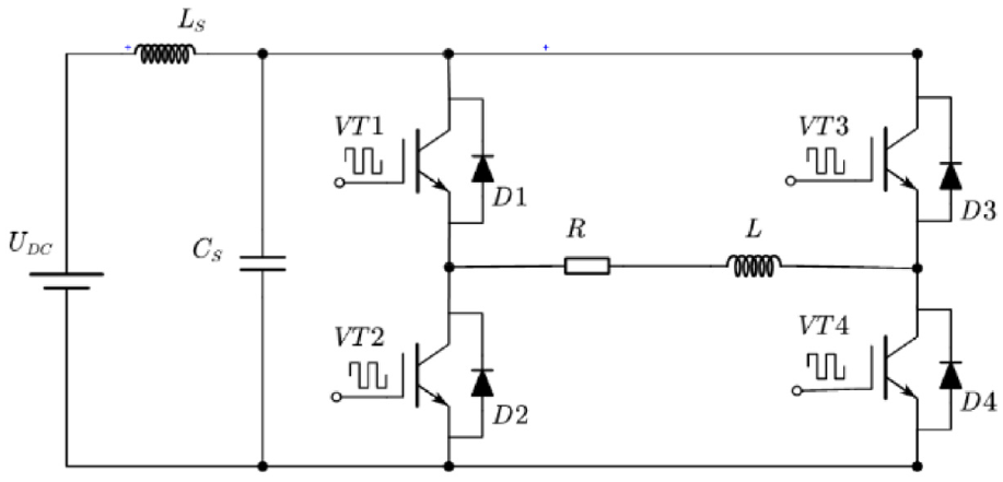
Circuit diagram of hard-switch suspension chopper.
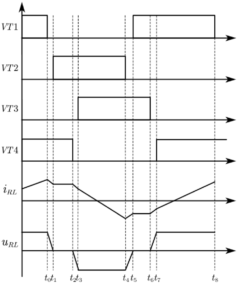
Taking the change of load current as an example, the waveform of hard-switch suspension chopper are analyzed as Figure 2, where PWM is the pulse control signal of the switch tubes,
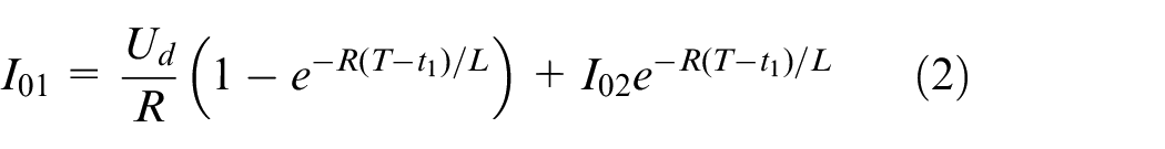
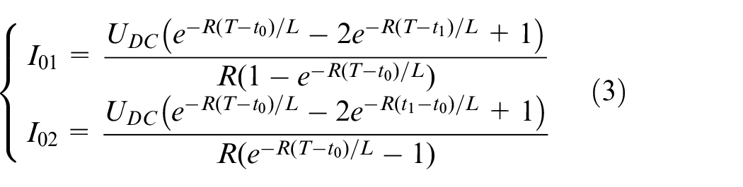
(1) In
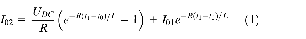
(2) In
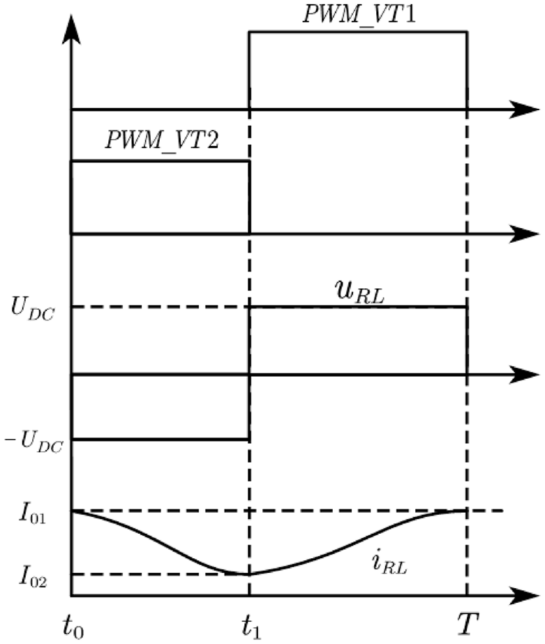
Waveform of hard-switch suspension chopper.
Simultaneous equations (1) and (2), the load current variation is shown as equation (3).
The traditional hard-switch suspension chopper has the advantages of simple structure and easy implementation, but there are also a series of problems such as large switching loss, inductive switching, diode reverse recovery, and electromagnetic radiation and noise. 5
Principle of PSFB suspension chopper
The principle of PSFB converter is to realize soft-switch by parallel capacitor of switch tube. When the switch tube is about to turn off, the voltage of it rises from 0 because the voltage of parallel capacitor is 0. When the switch tube will turn on, the freewheeling diode conduction makes the parallel capacitor voltage drop to 0, achieving zero-voltage switching. The key to realize soft-switch of PSFB converter is to ensure that the four switch tubes can meet the conditions of zero-voltage switching.
Since the zero-voltage condition of the lag arm of the PSFB converter is realized by the oscillation of the load inductance, there are problems such as the narrow range of the zero-voltage condition and the serious loss of the duty cycle.
20
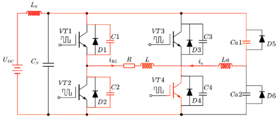
In this regard, the realization range of the soft-switch can be widened by adding an auxiliary circuit. The main circuit diagram of the PSFB suspension chopper is shown in Figure 3, where
Circuit diagram of PSFB suspension chopper.
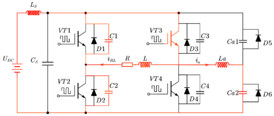
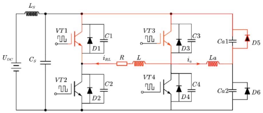
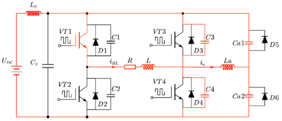
The control signals, load voltage, and current waveform of the PSFB suspension chopper are shown in Figure 4, and the current flow of modals are shown in Figures 5–12.
(1) Before time
(2) In
Waveform diagram of PSFB suspension chopper.
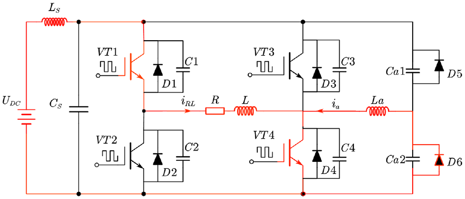
Modal 1.
Modal 2.
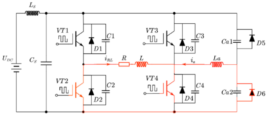
Modal 3.
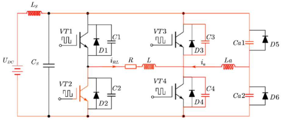
Modal 4.
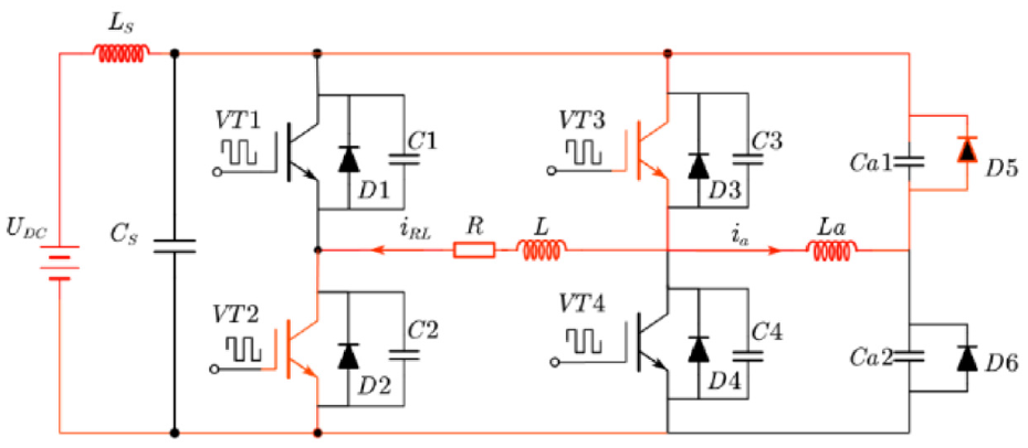
Modal 5.
Modal 6.
Modal 7.
Modal 8.
At
During this period, due to the large load inductance of magnetic levitation electromagnet, it can be considered that the load current is approximately constant, as shown in equation (5).

At this time, the collector-gate voltage changes of
(3) In
Since the angle corresponding to the
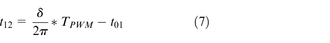
where,
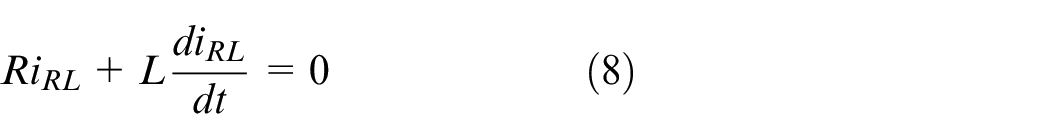
In this period, the current of auxiliary inductor decreases according to the change rate of
when

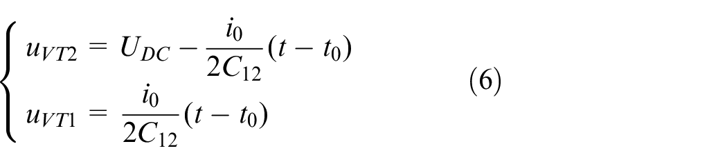
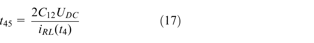
(4) In
At
During this period, the load works resonantly with
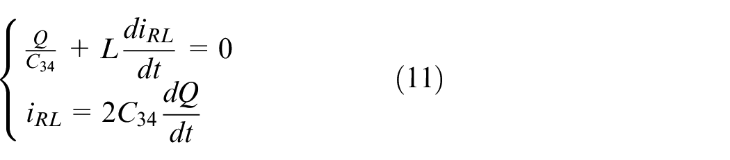
Bring the current value at time

The voltage of
where
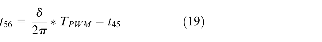
(5) In
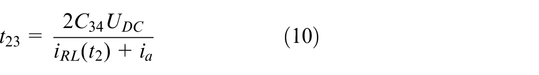
The conduction time of

During this period, the current of auxiliary inductor increases according to the change rate of
Bring the current value at time
(6) In
The current of auxiliary inductor decreases rapidly under supply voltage. The voltage of
During this period, it can be considered that the load current is approximately constant, as shown in equation (18).

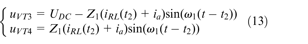
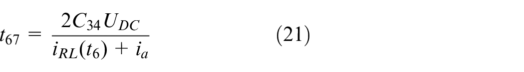
(7) In
Since the angle corresponding to the
During this period, the current of auxiliary inductor increases according to the change rate of

(8) In
At
In this period, the change law of load current is similar to that in

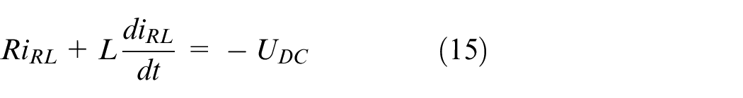
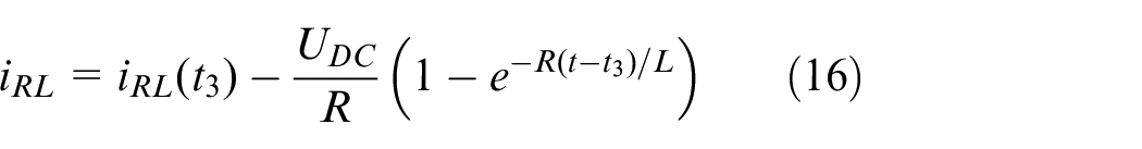
(9) In
The conduction time of

In this period, the power supply voltage acts on the load, and the load current rises according to the following rule.
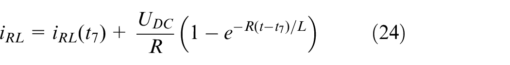
So far, the PSFB suspension chopper completes a full cycle of modal conversion, and enters the next cycle.
Design of circuit parameters
In order to realize the soft-switch of the PSFB suspension chopper, the dead time of the control signals and the parameters of the added components need to meet certain conditions.
Control signal
The dead time of signals has great influence on the performance of suspension chopper. The soft-switch cannot meet the implementation conditions if the dead time is too short. Conversely, it may cause waveform distortion, seriously reduce the output efficiency, and even adversely affect the stability of the chopper system if the dead time is too long. 21 The load of the suspension chopper is a large inductance element, and the dead time setting of the control signal can be determined by equation (25). 21
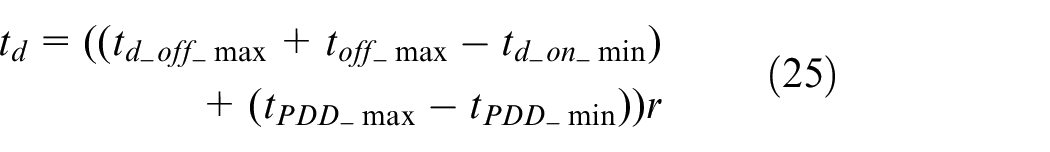
where,
Parallel capacitance
The selection of parallel capacitor parameters should meet the following conditions.
(i) In the dead time of IGBT, some modals should be completed in the dead time of IGBT, which prepares for the realization of IGBT zero-voltage turn on and turn off in the next modal.
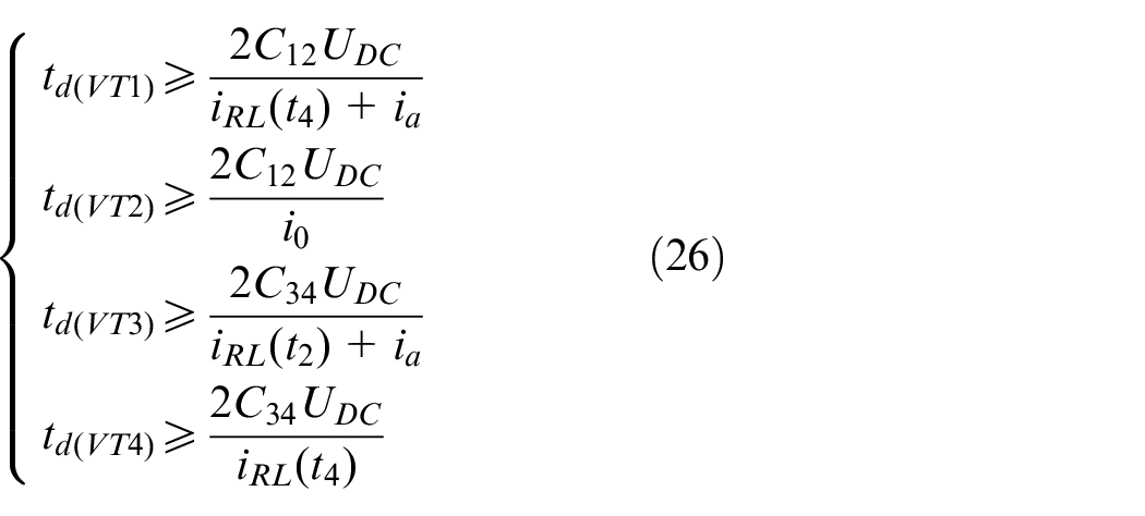
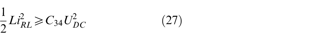
(ii) The parallel capacitor charging and discharging of the lagging arm is completed by the load inductance, so the load inductance needs enough energy, which needs to meet the following formula.
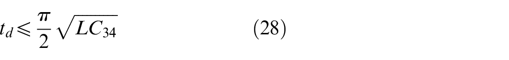
(iii) The inductor and parallel capacitor form an oscillation circuit. In order to eliminate the influence of the oscillation circuit, it is necessary to make the dead time less than one-fourth times of the oscillation period,22,23 namely to satisfy equation (28).
Auxiliary inductance
At steady state, the auxiliary capacitors
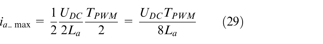
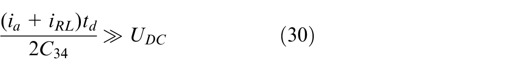
Under extremely light load conditions, the function of the auxiliary current is to complete the charging and discharging of the lag arm capacitance within the dead time, which needs to meet the following formula.
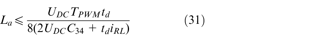
It can be obtained by simultaneous equations (29) and (30), and the auxiliary inductance needs to meet the following formula.
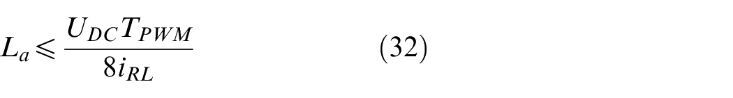
Ignoring the influence of the external capacitance on the auxiliary inductance, the upper formula can be simplified to the lower one.
Auxiliary capacitance
In the charging and discharging process of the lag arm, the auxiliary capacitors

where,
Result and discussion of PSFB suspension chopper
Simulation verification
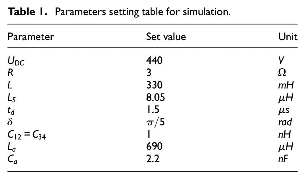
This paper used ANSYS Simplorer to simulate the circuit designed. According to the actual situation of the suspension chopper, FF300R12KT3 type IGBT is selected. Other parameters are set as Table 1.
Parameters setting table for simulation.
The simulation waveform of the load and
Load waveform of hard-switch chopper.
waveform of hard-switch chopper.
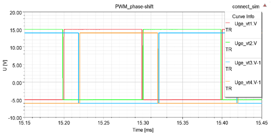
Control signals of PSFB chopper.
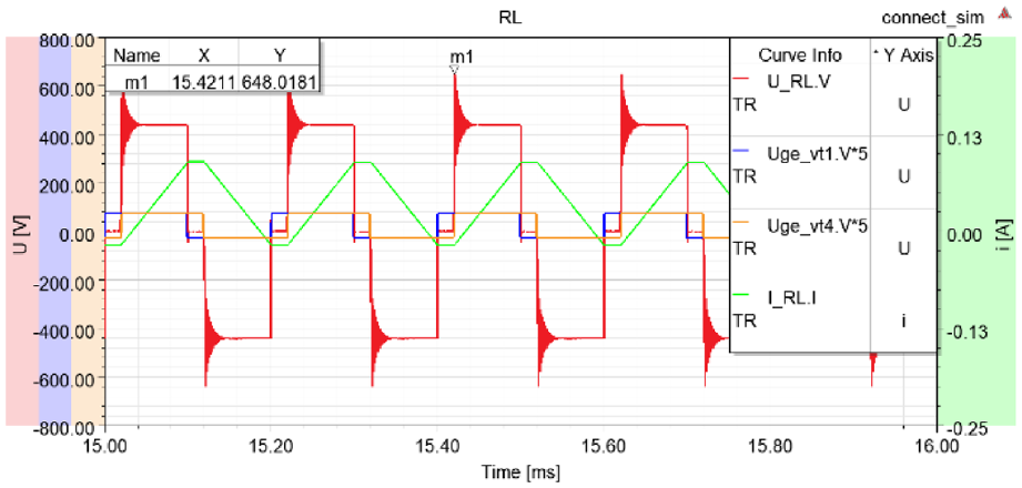
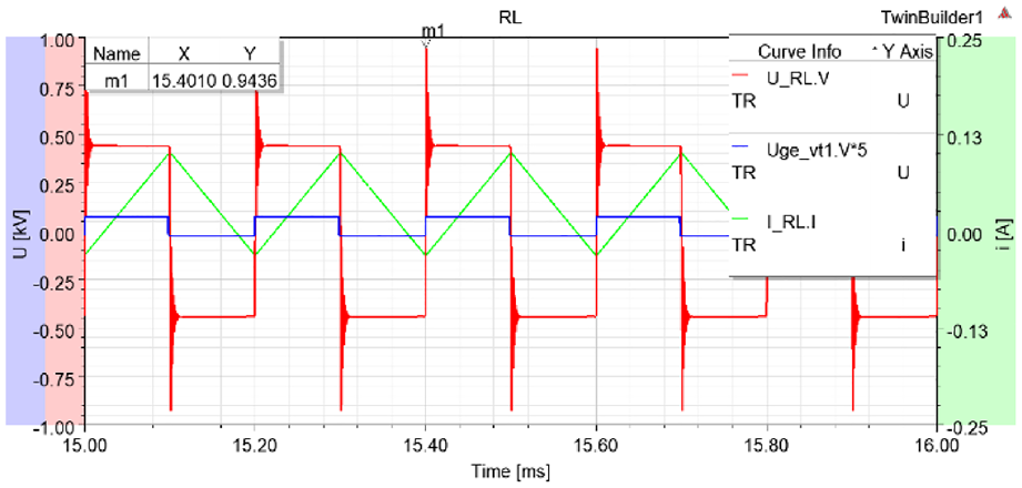
Load waveform of PSFB chopper.
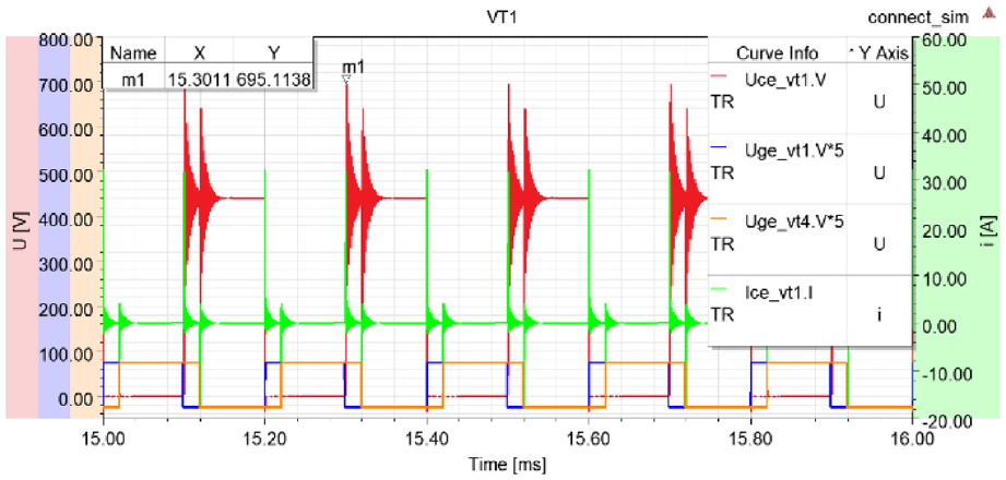
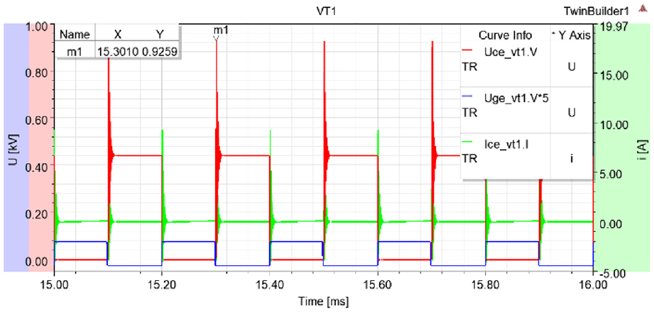
waveform of PSFB chopper.
It can be seen from Figure 13 that the current increases when
It can be seen from Figure 16 that the load current increases when
Figure 17 shows that due to the switching cross-talk of
Experimental verification
In order to test the suppression of voltage spikes by PSFB, a suspension chopper experimental verification platform is built, as shown in Figure 18.
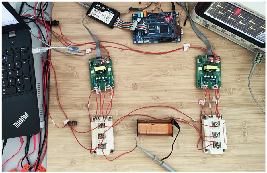
Experimental platform for suspension chopper.
Since the voltage spike and the supply voltage are approximately linear when the voltage spike does not exceed the short-circuit voltage of the switching tube, the power supply is set at a low potential level for experimental safety. Set the supply voltage
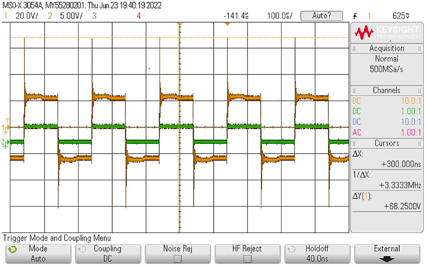
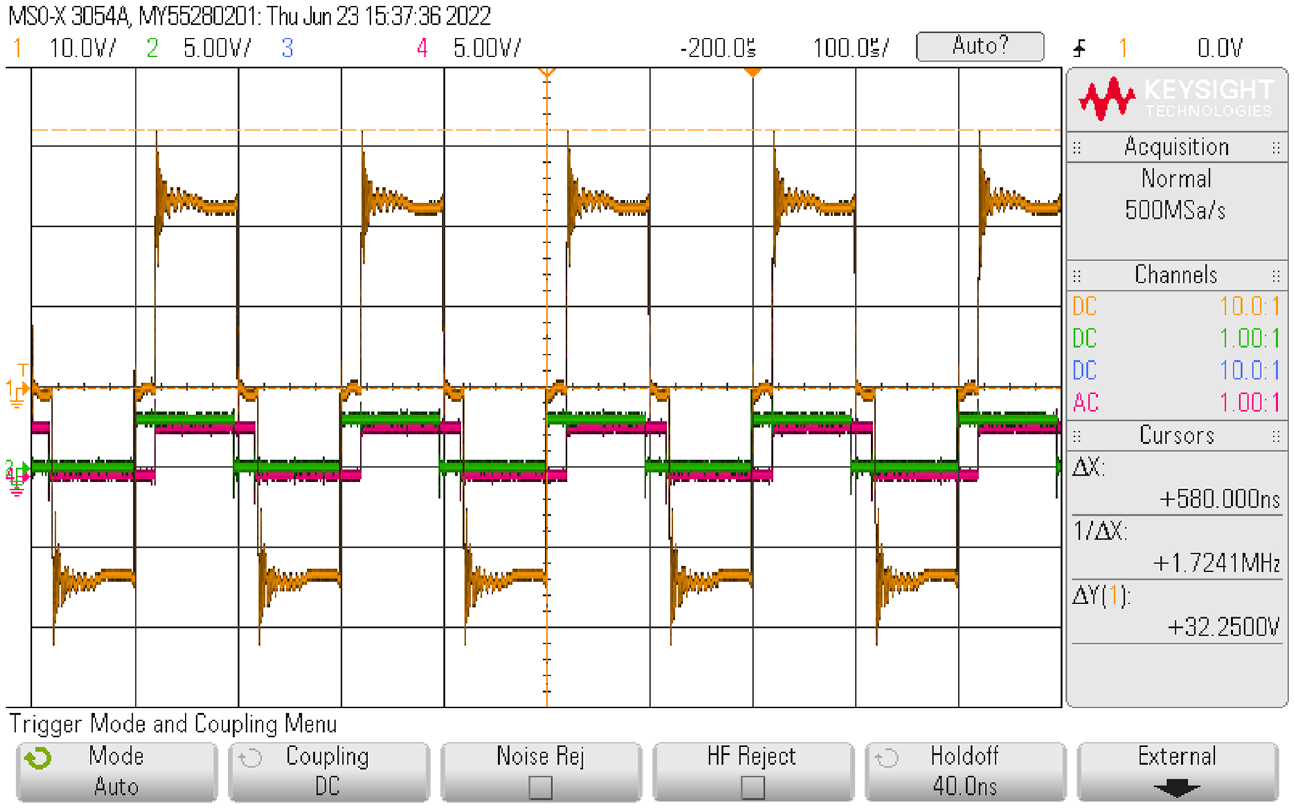
The experimental results of hard-switch suspension chopper are shown in Figures 19 and 20, and the experimental results of PSFB suspension chopper are shown in Figures 21 and 22. The yellow curve is the voltage of the load or
Load measured waveform of hard-switch chopper.
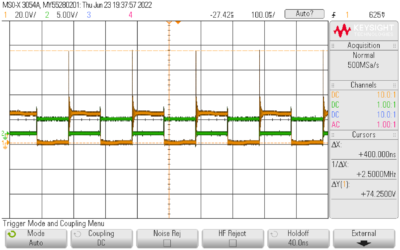
Load measured waveform of PSFB chopper.
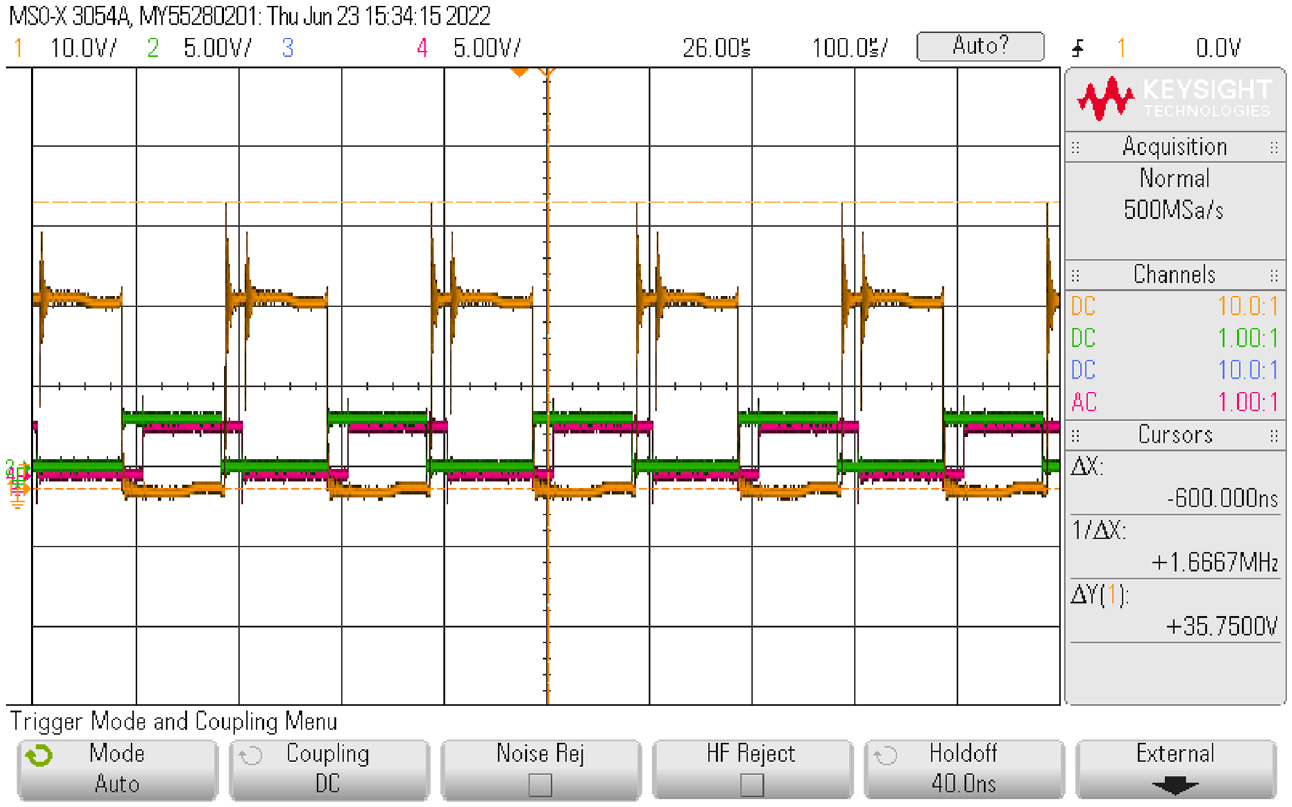
It can be seen from Figures 19 and 20 that when the supply voltage is set to 24
Figures 21 and 22 show that the peak load voltage of PSFB suspension chopper is 32.25
Based on the principle and experimental results of the designed circuit, it can be seen that compared with the suppression methods such as adding RCD circuit absorption or using clamp circuit, which are often used in engineering, the PSFB circuit has great advantages. First of all, and most importantly, the PSFB circuit can reduce the voltage spikes from about 200% to about 40%, and the suppression effect has been greatly improved. Secondly, the common methods need to add RCD absorption circuit or clamping circuit to each IGBT. In comparison, the PSFB circuit only needs one auxiliary circuit and several parallel capacitors, and fewer components are used. Finally, the main circuit switch still uses the hard-switch mode when the aforementioned methods are used, and its switching loss is very large. However, the main switch of the PSFB circuit is the soft-switch mode, which can effectively reduce the energy loss while suppressing the voltage spikes.
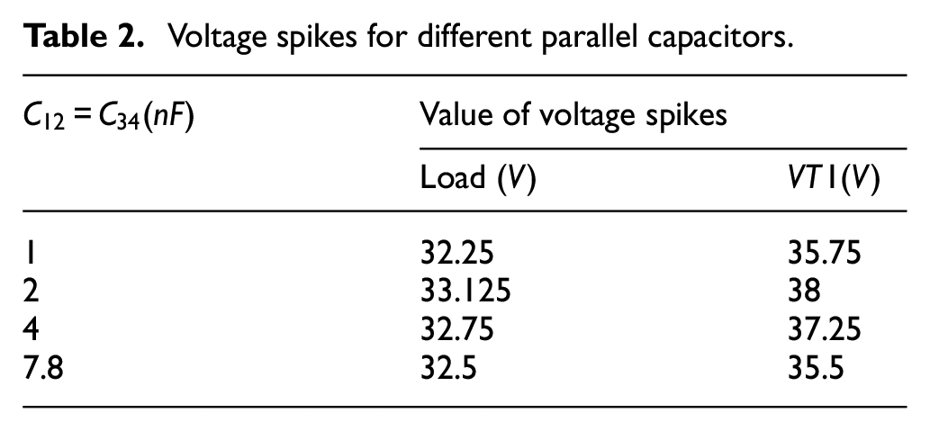
Furthermore, in order to test the influence of component parameters on the performance of the PSFB circuit, experiments were performed on different values of the parallel capacitance, auxiliary inductance and auxiliary capacitance of the suspension chopper. The results are shown in Tables 2–4.
Voltage spikes for different parallel capacitors.
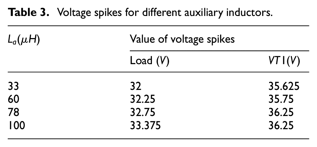
Voltage spikes for different auxiliary inductors.
Voltage spikes for different auxiliary capacitors.
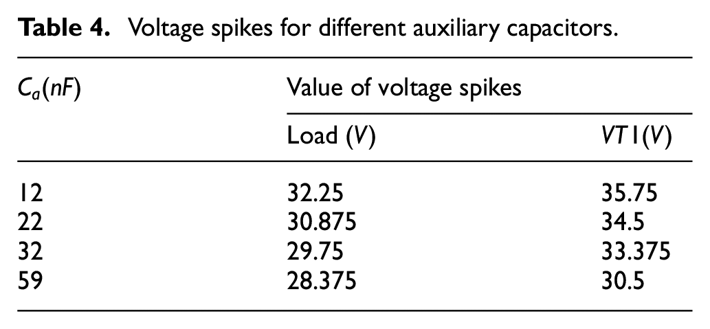
Table 2 shows that with the increase of parallel capacitance, the voltage of spikes load is almost constant, and the voltage spikes of
Table 3 shows that with the increase of the auxiliary inductance, the voltage spikes of the load and
Table 4 shows that the voltage spikes of load and
It can be seen from the above results that the PSFB circuit can always suppress the voltage spikes at lower positions as the component parameters change. That is to say, the effect of the PSFB circuit is not sensitive to the value of the added components, which is very conducive to the selection of circuit components, and also makes the circuit always have a good effect even when the parameters of the components change due to aging and different working conditions.
Conclusion
Aiming at the problem that the hard-switch suspension chopper in high-speed maglev train has large voltage spikes of load and IGBT, this paper proposes the PSFB suspension chopper. It only adds one auxiliary circuit and four parallel capacitors, using phase-shift control signals to make the four IGBT tubes achieve soft-switch sequential, which effectively reduces the voltage spikes.
Compared with the commonly used suppression methods such as adding RCD circuit to absorb or using clamping circuit, the PSFB circuit also has the advantages of using fewer components, effectively reducing energy loss and small influence of component parameters change on the suppression effect. The simulation and experimental results verify that the PSFB suspension chopper can reduce the voltage spikes of the load and IGBT to a lower value. Therefore, the PSFB circuit designed in this paper can provide a good reference for improving the suspension chopper system of high-speed maglev train.
Footnotes
Declaration of conflicting interests
The author(s) declared no potential conflicts of interest with respect to the research, authorship, and/or publication of this article.
Funding
The author(s) disclosed receipt of the following financial support for the research, authorship, and/or publication of this article: The work is supported by National Key R & D Program of China under grant 2016YFB1200602.