
Abstract
A novel any cell to any cell equalization circuit topology with small column, low weight, low cost, and high efficiency is proposed for serial-connected batteries, especially suitable for unmanned aerial vehicles, satellites, and other fields with strict requirements on size, weight, reliability, and safety. To solve the problems of high switching losses in equalization circuits and low reliability of complex control schemes. A half-bridge circuit to convert the DC voltage of the battery into AC voltage is employed, and the energy is exchanged autonomously via the bus. At the same time, LC resonant circuit is used to achieve zero-current switching of the MOSFET, thus reduces greatly the switching losses. The working principle is analyzed by theoretical derivation, and the parameters of the circuit are optimized through circuit simulation. Furthermore, experiments which support six cells equalization are carried out to verify the feasibility and advantage of this topology. This equalization uses a bus-type architecture to improve equalization efficiency and topological flexibility making it even more valuable in the industrial and aerospace fields.
Introduction
Lithium-ion batteries are widely used as energy storage elements in uninterruptible power supply, including unmanned aerial vehicles, satellite and aerospace fields. The harsh service environment of lithium batteries in the aerospace field can easily lead to unbalanced power between different cells in the battery pack, that is, the voltage values of different cells vary after a period of use. United operation will cause a small imbalance in respect of cells’ voltage among these cells due to inconformity individual cell properties. To improve effective capacity of a battery string and to prolong its lifetime, it is necessary to keep all cells’ voltages within a safety region and to minimize their voltage difference. Hence, cell-voltage equalization is an unavoidable issue for battery management systems (BMS).
Multiple voltage equalizers have been reported, roughly classified into the passive equalizer and the active equalizer. The passive equalizer is easy to implement, however, has low efficiency. The active equalizer enables the flow of electrical energy from a high voltage cell to a low voltage cell, so the energy consumption of equalization is reduced. According to the way the energy is transferred, the active equalization methods can be classified as single cell to single cell (C2C), single cell to string (C2S), multiple cells to multiple cells (MC2MC), and any single cell to any single cell (AC2AC).
The traditional C2C equalization topology avoids energy consumption of batteries and achieves the energy exchange between batteries to achieve balancing among them. However, it can only achieve energy balance between adjacent batteries. The equalization efficiency of the circuit decreases with the number of cells gradually increasing.1–5 The MC2MC equalization topology has a faster equalization speed than the traditional equalization topology and is more flexible as it can achieve equalization not only between any specific batteries but also between battery packs. However, the control scheme and circuit structure of this equalization topology are more complex and difficult to implement.6–10 Ahmad et al., 11 Zhou et al., 12 Lee et al., 13 utilized a C2S topology with an extremely high step-up or step-down conversion ratio when large battery strings are used, resulting in low energy conversion efficiency. The AC2AC topology was chosen, using capacitors as equalizers.14–19 Benefiting from their circuit structure, this class of balancing topology could exchange energy from a common energy bus, this type of equalization topology had a simple control scheme. Even if it did not decrease the equalization efficiency as the number of cells in series increases, it has yet not avoided the characteristics of weak antijamming ability and high switching losses. Liu et al. 20 utilized an inductor and capacitor to form a series circuit, which reduced the switching losses when the circuit operated at the resonant frequency, but this topology was used for energy transfer between cells. Liu et al. 21 allowed energy to be exchanged through a bus in the circuit to improve the equalization efficiency based on the previous paper. However, the number of cells for equalization in this topology should be even, thus leading to the limited practical application of this type of equalization circuit.
Compared to traditional balanced topologies, an equalization topology with a bus-based structure is proposed to enable the energy to be exchanged between any single cell and any single cell, which has the advantages of low cost, high efficiency, simple control scheme, and easy implementation. At the same time, the proposed equalization topology utilizes LC resonance to achieve zero-current switching of the MOSFET, reducing switching consumption to 2% and improving equalization efficiency to 96%, thus overcoming the common problem of switched-capacitor balanced topologies. Finally, the topology has no requirement for the number of equalization cells as long as the withstand voltage of the device is met, making it more advantageous in engineering applications.
Circuit principle
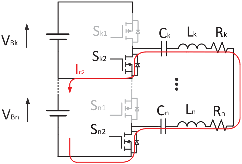
The topology of the equalization circuit proposed in this paper is shown in Figure 1(a), which supports the equalization of any cells in series (The schematic shows the balanced topology of n cells). In the equalization circuit, each cell is connected to a half-bridge circuit, consisting of a PMOS and an NMOS, the half-bridge circuit was chosen as the inverter circuit for this topology due to its light weight, simple control scheme, and high efficiency. The control signals shown in Figure 1(b). The half-bridge circuit is followed by a set of inductors, capacitors, and resistors resonating in series and connected to a bus for energy exchange between the cells.
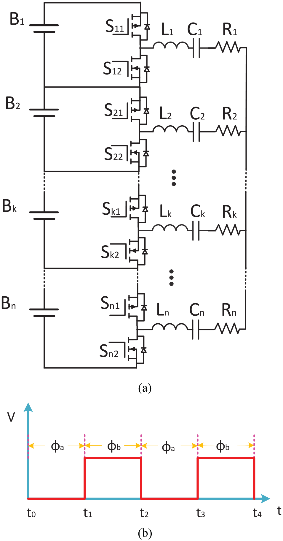
Control signal waveform and circuit topology: (a) bus-type equalization topology for zero-current switching and (b) control signals.
The parameters of the circuit are the same for the circuit connected to each cell. The control signal is a PWM wave with a duty cycle of 1:1. There are two operating phases when the bootstrap circuit reaches steady state: phase
Principle analysis of the circuit at the stage
At stage
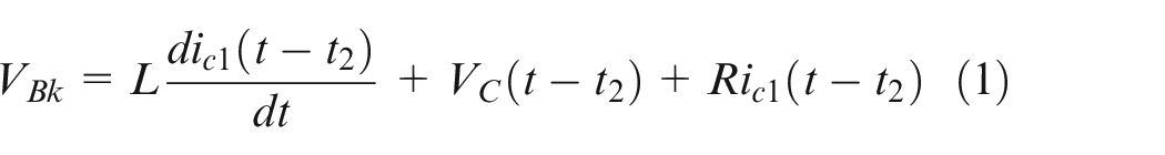
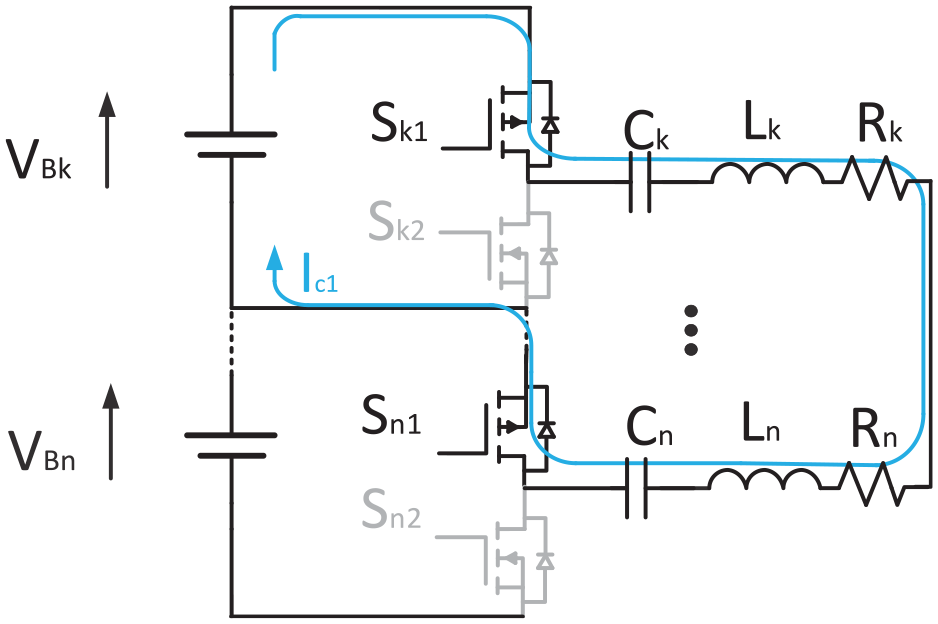
Phase
In the equation, L is the sum of the inductance values in the circuit, R is the total resistance, C is the value of the capacitance after the series connection, and the VC is total voltage after the capacitance storage.
A Laplace variation on equation (1), the equation (2) can be expressed as
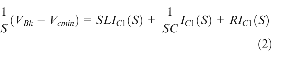
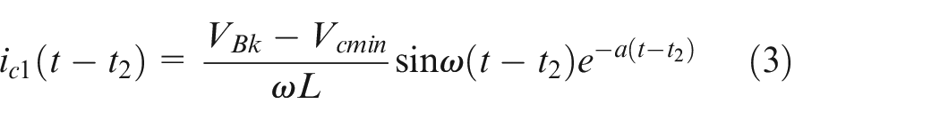
Thus equation (3) for the current can be expressed as
Resonant frequency in the above equation
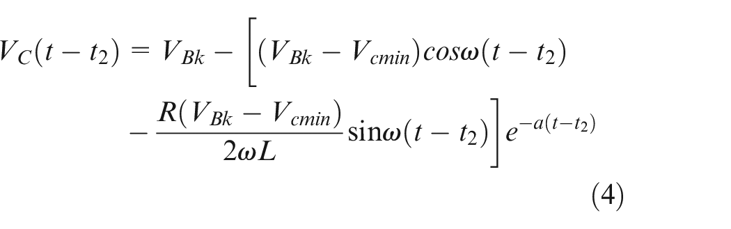
Equation (4) gives that at the moment the capacitor energy storage reaches its maximum value

Principle analysis of the circuit at the stage ϕb
At stage
Phase
The same solution as previously described yields the voltage expression for both the current
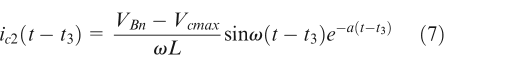
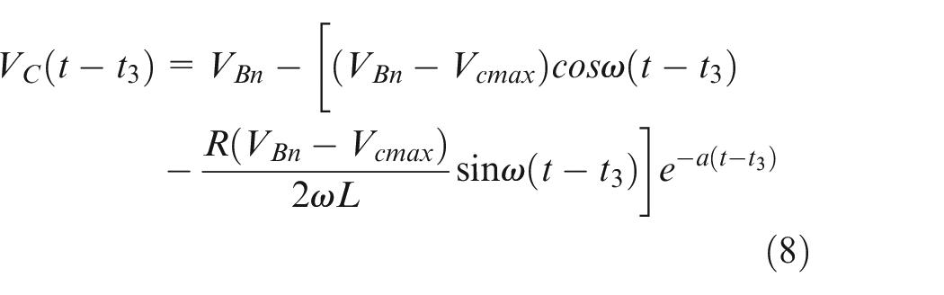
Through the equation (8), the minimum energy storage of the capacitor is reached at the moment

The difference between the voltage of the highest energy storage of the capacitor and the voltage of the lowest energy storage is obtained
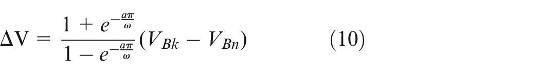
The average current is expressed in the following equation:

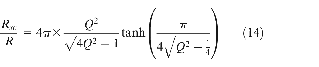
Combined with equation (11), the equivalent resistance
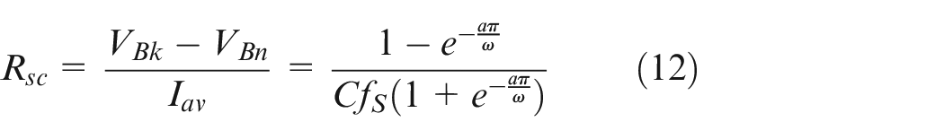
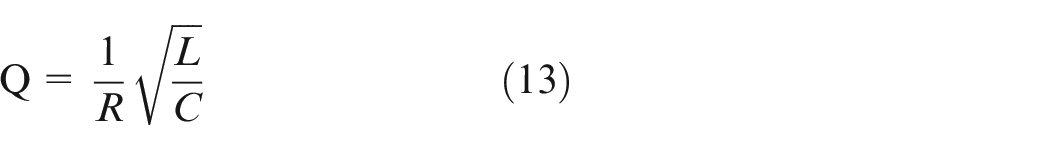
The quality factor Q can be expressed as:
At this point in the equation (12) is the value of capacitance C, inductance value L, resonant frequency
All the above occurs when the circuit is operating at the intrinsic frequency. If the circuit is operating at a frequency that deviates from the resonant frequency, then the zero-current switching condition will not be met resulting in higher switching losses.
Figure 4 illustrates the relationship between the values of
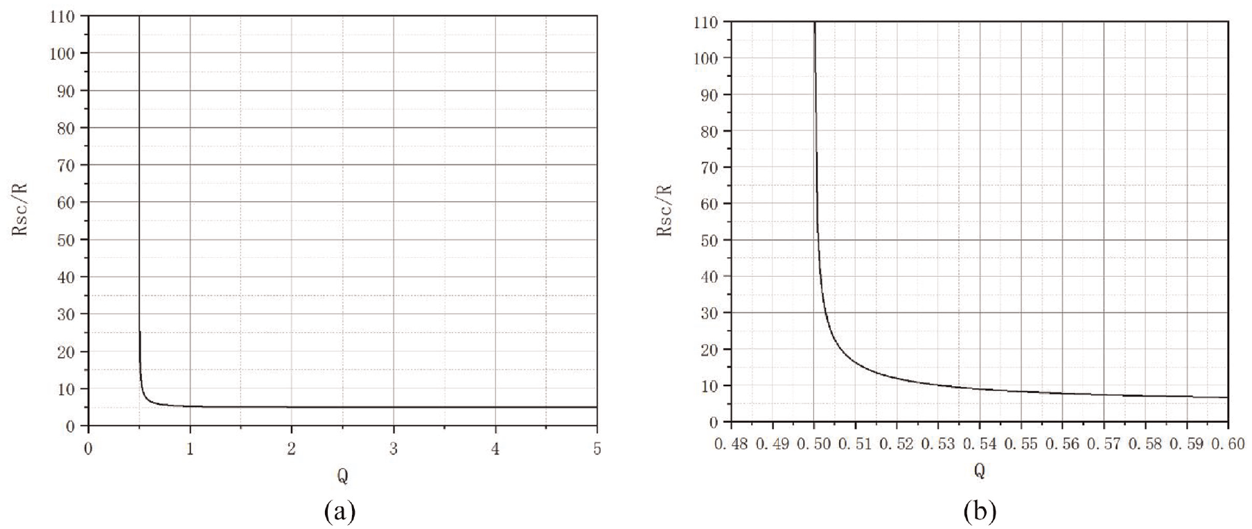
Relationship between equivalent resistance and Q-value: (a) complete change curve of Q-value and (b) equivalent resistance variation curve for Q-values between 0.48 and 0.6.
It can be seen from equation (14) that MOSFET zero current on and zero current off can be achieved on the basis that the control frequency is the inherent frequency of the circuit and the quality factor Q is greater than 0.5. It can be seen from Figure 4 that after the Q-value is above 2, there is no significant reduction in losses as the Q-value increases, and the value is stable at around 5 R.
According to the above discussion, RSC is the equivalent resistance between any two batteries. Based on the mathematical model given in Ye et al., 17 the following equivalent circuit model can be obtained, the equivalent circuit diagram is shown in Figure 5.
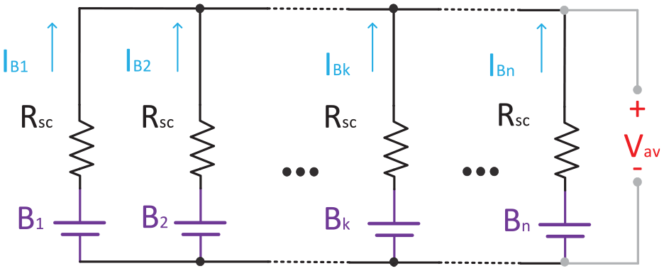
Equivalent model of the circuit.
Assuming that
Balancing efficiency analysis of circuits
The input power Pin and output power Pout of the circuit can be expressed as:
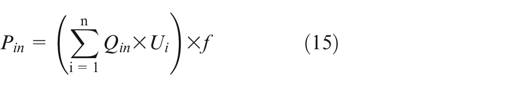
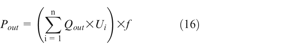
Q in in equation (15) is the charge flowing into the corresponding cell in one period and Qout in equation (16) is the charge flowing out of the cell in one period, f is the frequency.
The switching loss has two components, Pc is the conduction loss and Ps is the switching loss, where Pc and Ps are the corresponding conduction and switching losses for each MOSFET:

In equation (17)RDS is the on-resistance of the MOSFET and IDS is the current flowing between the drain and source of the MOSFET at this time.
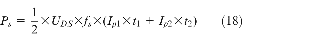
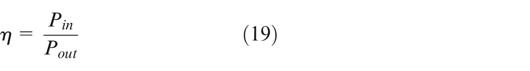
In equation (18)t1 is the time when the MOSFET is not fully on and the Ip1 current is the current flowing between the drain of the MOSFET and the source stage during this time, t2 is the time when the MOSFET is not fully off and the current Ip2 is the current flowing between the drain of the MOSFET and the source stage during this time, where the values of t1 and t2 can both be found in the datasheet of the MOSFET. The equilibrium efficiency η can be expressed as:
Circuit simulation and verification
The circuit schematic is drawn using Saber simulation to simulate the circuit topology of a four string LC resonant equalizer based circuit, the simulated circuit diagram is shown in Figure 6. The initial voltages of the four strings are 3.2, 3.4, 3.6, and 3.8 V. The four inductors are 10 μH, the four capacitors are 24.2 μF (22 μF in parallel with 2.2 μF) and the resistors are chosen to be 40 mΩ to simulate the line losses and MOSFET conduction losses in the actual circuit. The drive circuit makes use of capacitors for level isolation, and the control signal is a square wave with a duty cycle of 50%, a frequency of 10 kHz and a peak-to-peak value of 10 V (As long as the voltage signal here can drive the MOS tube). The Q-value of the equalization circuit is 15.7, which theoretically satisfies the conditions of zero-current on and zero-current off.
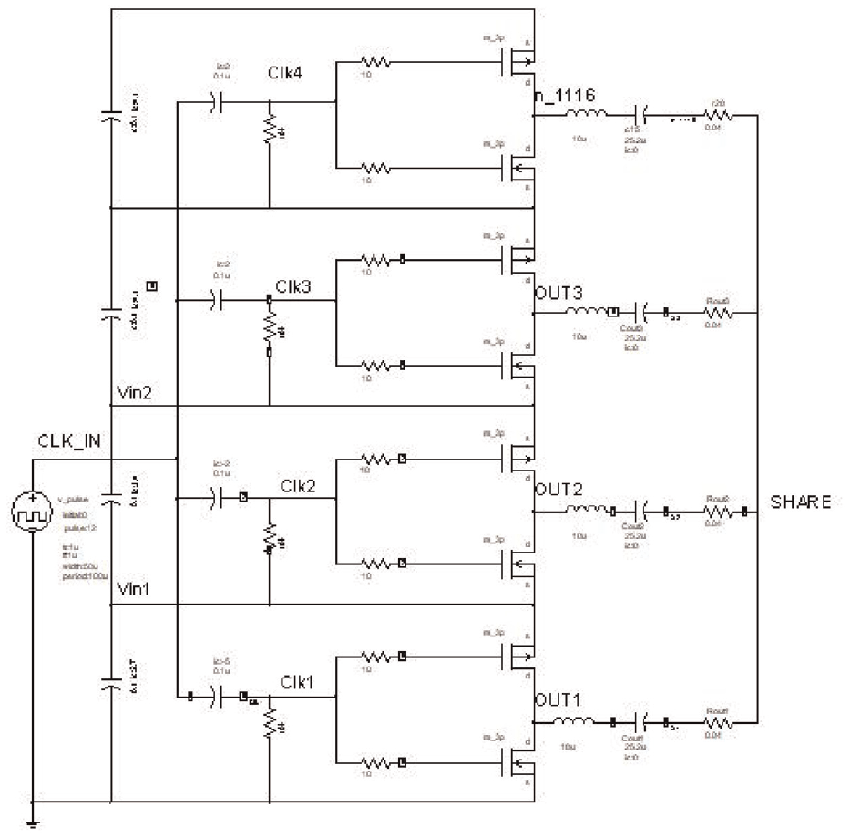
Simulation of a bus-type equalization circuit that enables zero-current switching.
Figure 7 shows the current flowing through the series LC resonant equalizer when the time is between 1 and 1.8 ms. As can be seen from the figure the circuit topology achieves zero current switching.
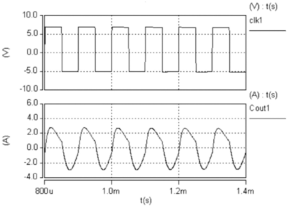
Current curve of the resonant equalizer.
Figure 8 shows the variation curve of the battery voltage during the equalization process. After 3 s the battery voltage reaches uniformity, proving the effectiveness of the equalization topology.
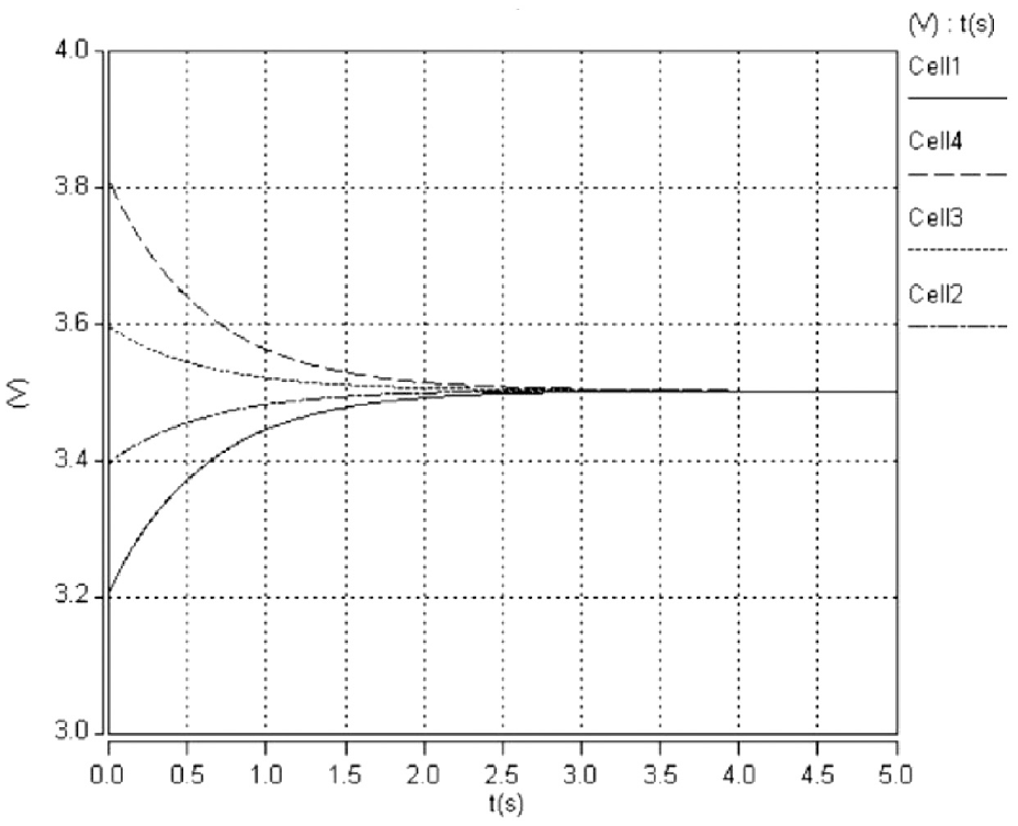
Variation curve of the battery voltage during equalization.
Circuit experiments and tests
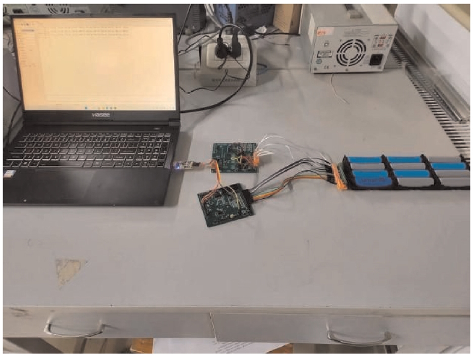
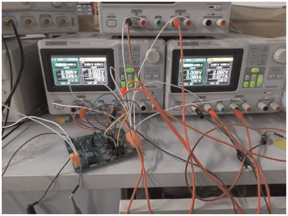
Figure 9 shows the actual board, which has a total mass of only 44.2 g.
Actual circuit diagram.
Figure 10 shows an experimental diagram of the actual circuit. Frequency of control signals and the passive components used in this circuit are shown in Table 1.
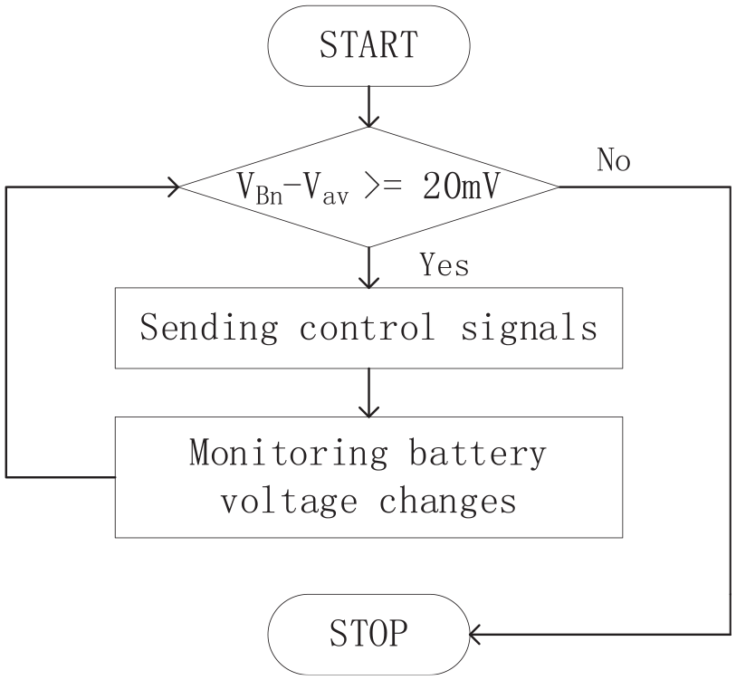
The software flowchart of the equalization circuit in this article.
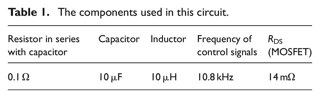
The components used in this circuit.
The software flow chart of the balancing topology for this time is shown in Figure 11. VBn is the voltage of each battery cell and Vav is the average value of all the battery cell voltages. Benefiting from the relatively simple control process, the reliability and feasibility of this balancing topology are relatively high.
Experimental diagram of the actual circuit.
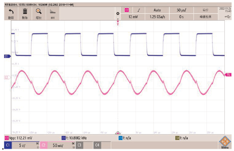
After calculations and experimental verification, the optimum frequency of 10.8 kHz was found for the circuit operation. Figure 12 shows the control signal at this frequency and the waveform of the equalization current, and the curve proves that the MOSFET is operating in a soft switching state.
Waveforms of control signal, equalization current.
Using a DC power supply with a resistor to simulate a battery, connect the six power supplies to the equalization circuit, changing the voltage of the third supply to 3.4 V and the others to 3 V. Observe the equalization current of the second circuit (the equalization current peaks at 112 mA) and the control signal waveform.
The resonant frequency in the simulated waveform is not exactly the same as the resonant frequency of the actual circuit due to the line consumption in the actual circuit and the difference between the inductor and capacitor values. The resonant frequency of the circuit is 10.8 kHz, as can be seen from the final current waveform.
After 180 min of accessing a battery pack with voltages of 3.64, 3.71, 3.79, 3.85, 3.83, 4.05, and 4.06 V, the battery completed equalization and the curve of voltage change during equalization is shown in Figure 13.
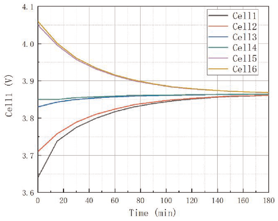
Voltage variation curve during battery equalization.
The experimental results in this paper are consistent with the simulated graphs, and the experimental current waveforms match the simulated waveforms, proving the correctness of the equalization topology theory. The experimental results are compared with other equalization topologies.
Figure 14 illustrates the experimental equalization results of the proposed equalization circuit in this paper for six series-connected Li-ion cells.
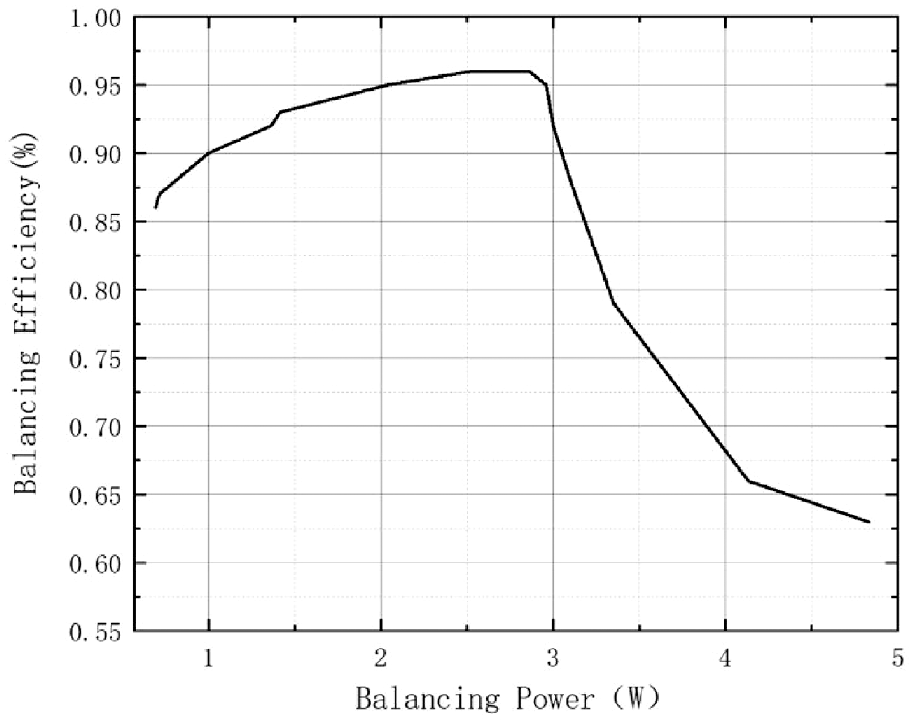
The balanced effect of the experiment.
The equalization efficiency of 96% was achieved at an equalization power of 2.86 W, a significant improvement caused by the zero-current switching proposed in this paper. However, the converters of this circuit cause energy loss, limiting the further increase of the balancing efficiency.
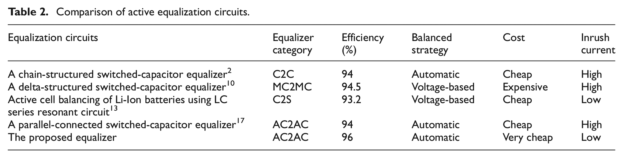
Table 2 shows the performance of the equalization topology in this paper compared to other types of equalization topologies, including equalization efficiency, board cost, equalization strategy, and inrush current. The superiority of the present equalization topology is shown.
Comparison of active equalization circuits.
Conclusion
The equalization topology proposed in this paper enables energy transfer between any single cell, and the equalization efficiency is independent of the number of cells. By means of LC resonance, zero-current switching is achieved to reduce switching losses. At the same time, the equalization topology has the advantages of light weight, high efficiency and low cost, making it ideal for UAV and aerospace applications. This topology allows the size and cost of the circuit to be further reduced by varying the control frequency and the value of the passive components, while the equalization efficiency is not reduced.
Footnotes
Declaration of conflicting interests
The author(s) declared no potential conflicts of interest with respect to the research, authorship, and/or publication of this article.
Funding
The author(s) received no financial support for the research, authorship, and/or publication of this article.