
Abstract
In recent years, since the unique advantages in automotive structures, the vehicle active suspension systems have received widespread attentions. A good active suspension system can reduce the vibration and improve the overall performance of the vehicle. Therefore, the design of the controller for the active suspension system to perform autonomous adjustment plays a vital role in vehicle comfort and safety. For the active suspension of the seven-DOF sport utility vehicle (SUV) model, this paper takes the vehicle body acceleration, tire dynamic load and suspension dynamic travel as the indicators to evaluate the performance, and the proportional-integral-derivative (PID) controller is designed to improve the performance of the vehicle active suspension system. Based on the software of MATLAB/Simulink and Carsim, a closed-loop co-simulation model diagram is established, which includes a PID controller module. Meanwhile, the random road input model and the whole vehicle model are constructed in Carsim. Finally, at the speeds of 70, 90, and 120 km/h, the active suspension system under the designed PID controller is simulated and compared with the passive suspension system. The simulation results show that the active suspension system based on PID controller can effectively improve the overall performance of the vehicle, and then the comfort and safety of the vehicle can be further enhanced.
Keywords
Introduction
With the increasing demand for automobiles in modern society, improving the comprehensive performance of automobiles has become one of the hotspots in current automotive research. As an important part of the vehicle chassis, the suspension systems, which can effectively improve the overall safety and stability of the vehicle, see Hrovata, 1 Rath et al., 2 and Lin and Lian. 3
In order to improve the performance of the suspension system, a series of results have been achieved in works.4–10 The authors Zhang et al. 4 proposed an adaptive neural network (NN) optimization control strategy for the seven degree of freedom active suspension system to improve the driving safety and riding comfort of the vehicle. The authors Cao et al. 5 presented a robust control strategy for an automotive active seat suspension system with sampled measurements. The authors Sun et al. 6 developed an adaptive robust control technique to design a controller and stabilize the driving attitude of the vehicle. The authors Gu et al. 7 presented a control strategy for a class of semi-active seat suspension systems with norm-bounded parameter uncertainty. The authors Wei et al. 8 proposed a control method for an active seat suspension system in the finite frequency domain to match the characteristics of the human body. The authors Bououden et al. 9 investigated robust model predictive control (RMPC) for active suspension systems with time-varying delays and input constraints. Subsequently, the authors Zhao et al. 10 studied the output-feedback control problem of the vehicle active seat suspension system and proposed a novel optimal design method of the output feedback controller.
As a traditional control strategy, PID has the advantages of convenient parameter adjustment, high stability and strong adaptability, which is widely used to improve the overall performance of automobiles, see Refs.11–14 The author Anh 11 designed a classical PID controller for an active suspension model in MATLAB/Simulink, and used the designed PID controller to optimize the vertical acceleration of the vehicle body, thereby improving the drivability of the vehicle. The authors Tian and Nguyen 12 developed a PID controller for the eight-degree-of-freedom active suspension system model in MATLAB/Simulink, which has obvious effects in damping vibration and restraining body shake. The authors Zhao et al. 13 proposed a control algorithm for generating every movement of the vehicle based on vehicle lateral dynamics and adaptive PID control. The authors Zhao et al. 13 proposed a control algorithm based on vehicle lateral dynamics and adaptive PID control, which is used to generate each movement of the vehicle. The authors Nie et al. 14 presented a new strategy called adaptive PID of radial basis function NN, which can improve the longitudinal velocity tracking accuracy of autonomous vehicles.
In this paper, the PID controller module is designed in MATLAB/Simulink programing software for the active suspension system of a seven degree of freedom SUV model, and the PID control parameters are adjusted online. In order to fully reflect the actual operation and vibration of the vehicle, a random road input model and a vehicle model are constructed in Carsim software. Then, a closed-loop joint control is formed through MATLAB/Simulink and Carsim. Finally, simulation comparisons are made with passive suspension systems under the same overall conditions. The co-simulation results show that the active suspension system based on the PID controller can effectively improve the overall performance of the vehicle, and has a significant effect on improving the driving safety and riding comfort of the vehicle.
Establishment of random road input model and vehicle model
The establishment of random road input model
In order to reflect the overall performance of real vehicles more accurately, a random rough road is selected as input. By forming an integrator and a filter, the random road input is generated from the Gaussian white noise. 15 The random rough road input satisfies:

where
According to the difference between the power spectral density of pavement and the roughness of domestic pavement, the random pavement is divided into eight levels. In order to approximate the actual operating conditions, the C-level random road surface is selected as the input, and the road surface roughness coefficient is
When the vehicle speed is 70 km/h, the input response curve on the C-level random road surface is shown in Figure 1.
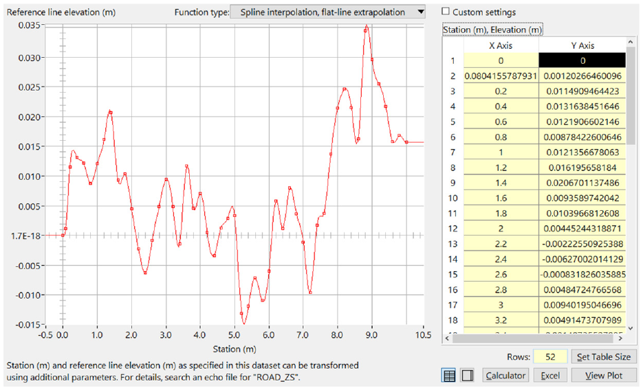
Random road input response curve at 70 km/h.
The establishment of vehicle model
In order to study the performance of the vehicle active suspension system, a vehicle model that can accurately reflect the vibration states of the active suspension system is required. The actual vehicle is described as a Seven-DOF vehicle model,16,17 which includes the vertical motions, pitch motions, roll motions of the vehicle, and the jumps of the vehicle’s front and rear tires. The active suspension model of the Seven-DOF vehicle is shown in Figure 2.
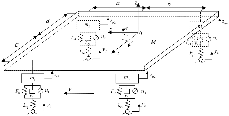
Seven-DOF active suspension model.
According to the second law of Newton’s mechanics, the dynamic differential equation of the Seven-DOF vehicle active suspension system can be expressed as:
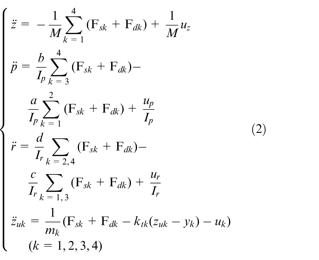
where
Through the analysis of the vehicle’s Seven-DOF active suspension system model, the vibration forces in the vertical direction, pitch direction and roll direction of the vehicle body are expressed as
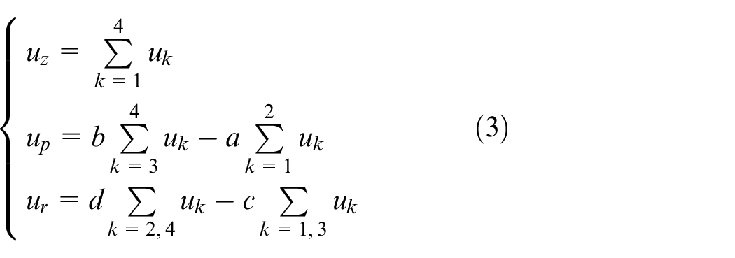
The SUV vehicle is selected as the research object. According to the pseudo-inverse operation in MATLAB, the relationship between the input control force of the four exciters and the vibration reduction force in the vertical direction, pitch direction, and roll direction of the vehicle body can be obtained as follows
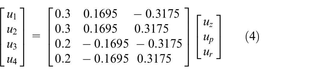
where
Carsim is a professional simulation software, which is applied to vehicle dynamics design. The vehicle model construction in Carsim software includes seven subsystems: vehicle body, steering system, braking system, suspension system, powertrain system, tires and aerodynamics. 18 In order to accurately reflect the overall performance of the actual SUV suspension system, Carsim is used to establish an E-type SUV vehicle model. The body module setup is shown in Figure 3.
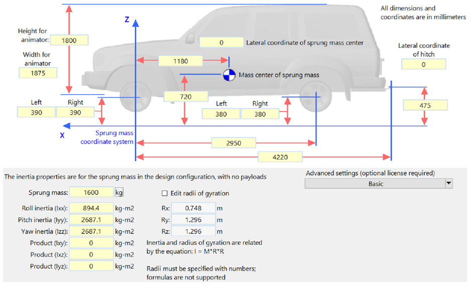
The vehicle body module settings.
In order to satisfy the dynamic differential equation of the vehicle active suspension system, the parameters of the body module are set to
In the process of modeling the vehicle, the independent suspension composed of springs and dampers is selected in the Carsim software. The kinematic characteristics (K characteristics) and the compliance characteristics (C characteristics) of the front and rear independent suspensions are set in Figure 4. The tire specification is 265/75R16, and the model parameters of the front and rear tires are shown in Figure 5.
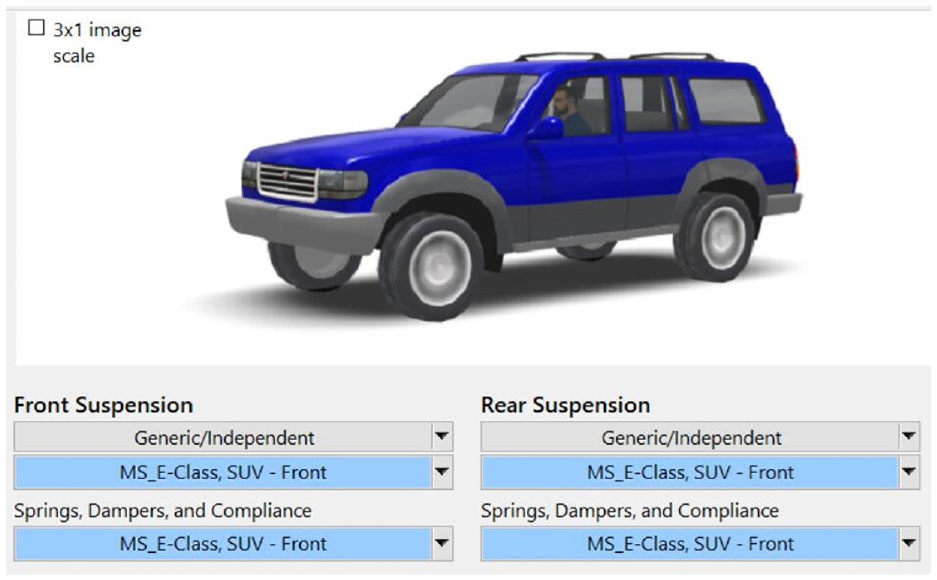
The front and rear independent suspension settings of vehicle.
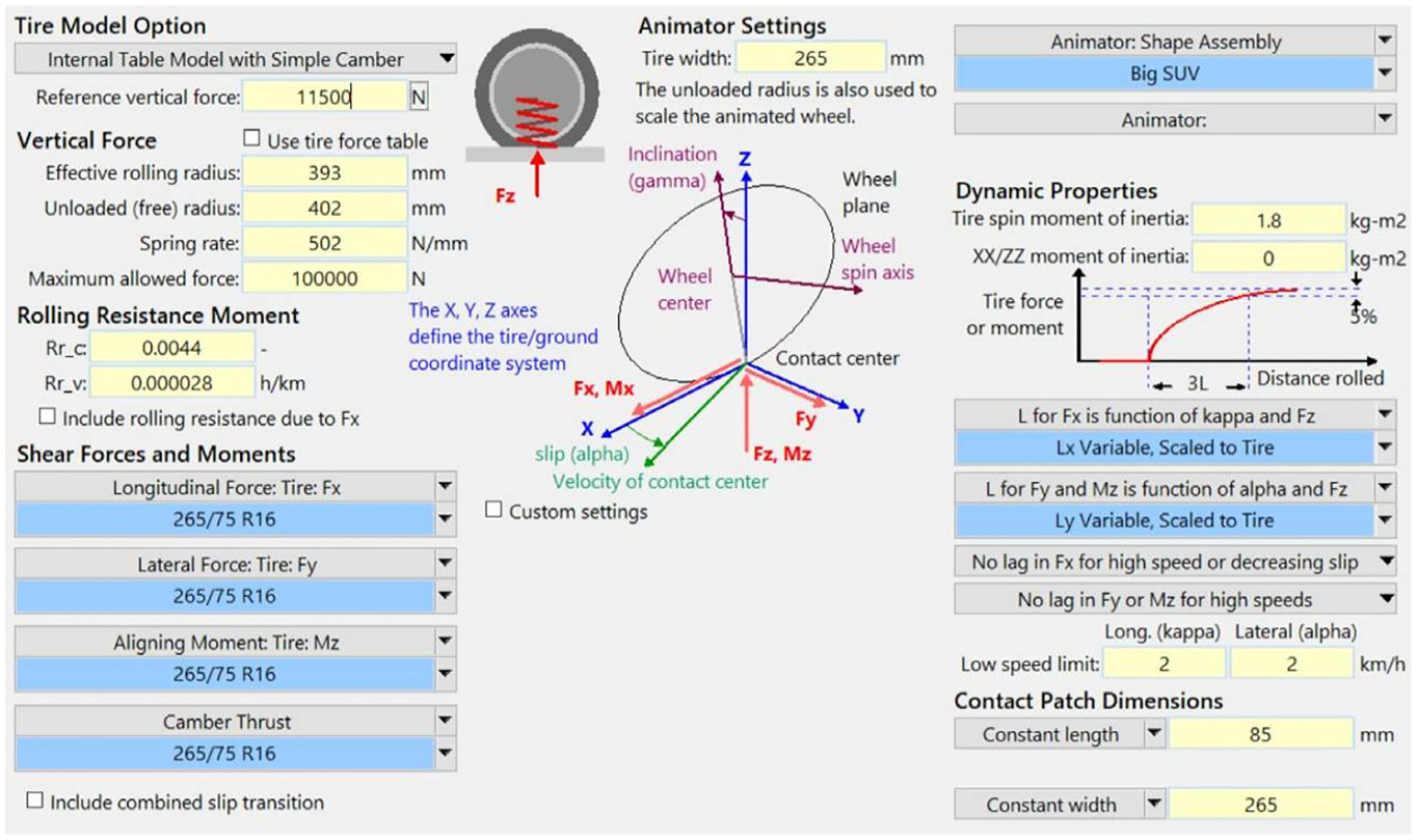
Settings for the tire model.
PID controller design
The PID controller is a traditional industrial control strategy that obtains the deviation signal by comparing the detected signal with the set value. New signal inputs can be calculated and processed by the offset values. Then, the system data can better track the preset values. The PID control system is mainly composed of PID controller and controlled object. The stability and accuracy of the system can be improved by adjusting the parameter values of the PID controller through empirical methods.19,20 The block diagram of the PID control system is shown in Figure 6.
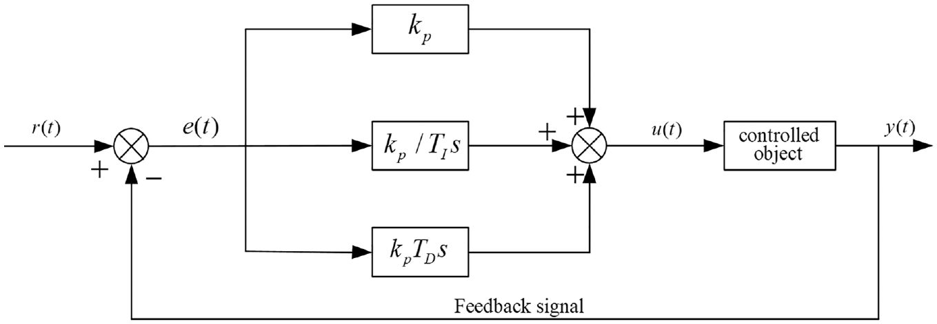
PID control system structure block diagram.
The relationship between the input deviation
where
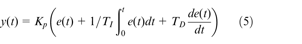
In the design process, the PID controller A in the vertical direction of the vehicle body is taken as an example. The simulation sub-module of PID controller A in the vertical direction of the vehicle body is constructed in MATLAB/Simulink software, as shown in Figure 7. The vertical acceleration of the vehicle body is used as the controlled object of the PID controller. The input deviation of the PID controller A is
The simulation sub-module of PID control system A.
Carsim and MATLAB/Simulink co-simulation research
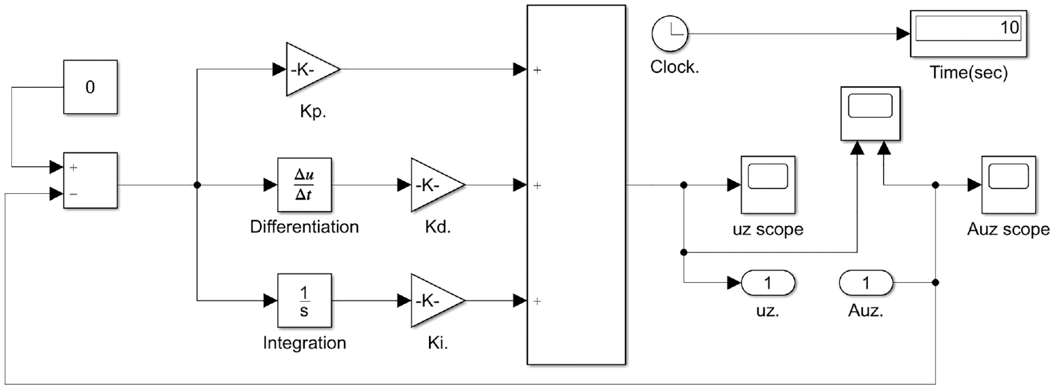
Based on the design of three PID controllers in the vertical direction, the pitch direction and the roll direction of the vehicle body, the control principle diagram of the vehicle active suspension system is shown in Figure 8. Its main working principle is: when the vertical acceleration
The control principle diagram of the vehicle active suspension system.
Similarly, when the body roll angle acceleration
When designing the control strategy of the vehicle active suspension system, a simulation model is jointly established through MATLAB/Simulink software and Carsim software.22,23 In MATLAB/Simulink, the generated Simulink module is connected with the Carsim module for input and output to construct a closed-loop joint control. The co-simulation block diagram between Carsim and Simulink is shown in Figure 9.
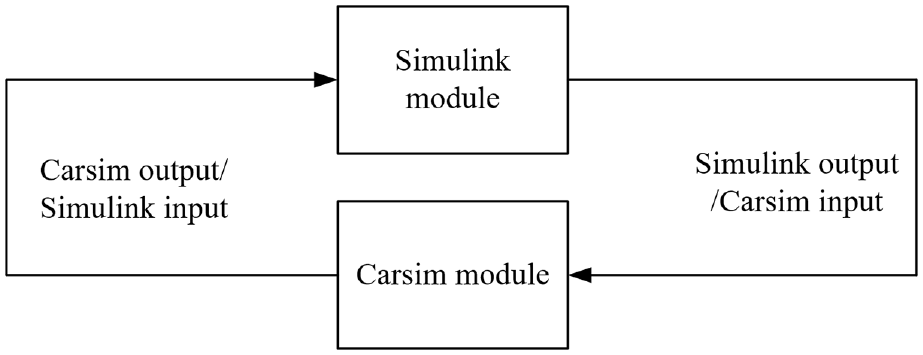
Block diagram of the co-simulation between Carsim and MATLAB/Simulink.
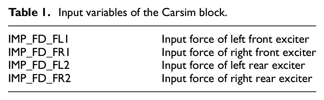
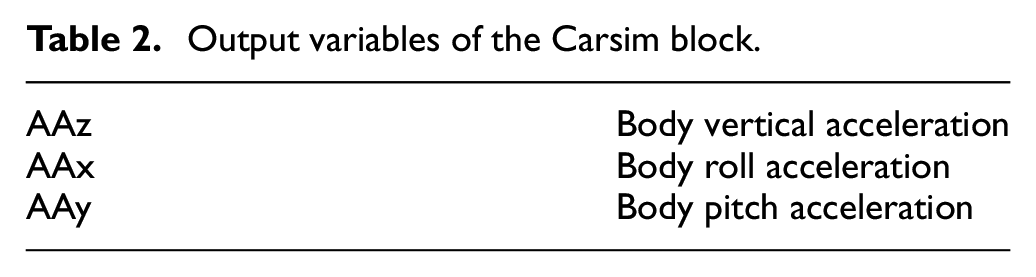
In the co-simulation, the controller designed in the Simulink module controls the output parameters set in the Carsim module in real time, and the output results are fed back to the Carsim module to form a closed-loop joint control and re-calculate the control. In order to establish the closed-loop control model of Carsim and MATLAB/Simulink, the input and output variables of the Carsim module are set in the Carsim software, where the input settings of the Carsim module are shown in Figure 10, and the input variables are shown in Table 1. The output settings of the Carsim module are shown in Figure 11, and the output variables are shown in Table 2.
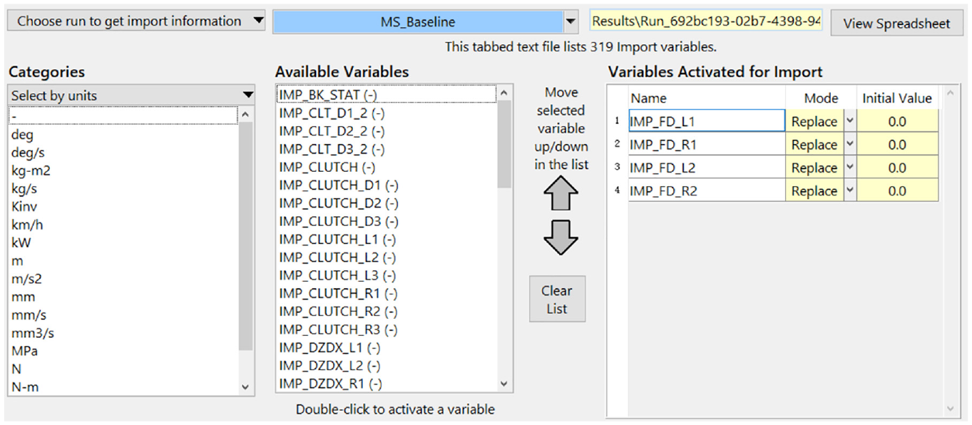
Input settings for the Carsim module.
Input variables of the Carsim block.
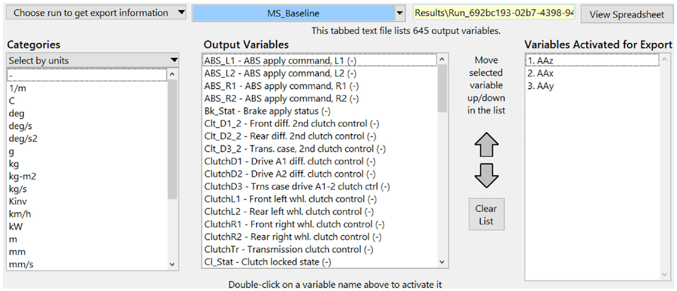
Output settings for Carsim modules.
Output variables of the Carsim block.
Based on the control block diagram of the vehicle active suspension system, the block diagram of the co-simulation of Carsim and MATLAB/Simulink software, the closed-loop co-simulation model is built in Simulink, as shown in Figure 12.
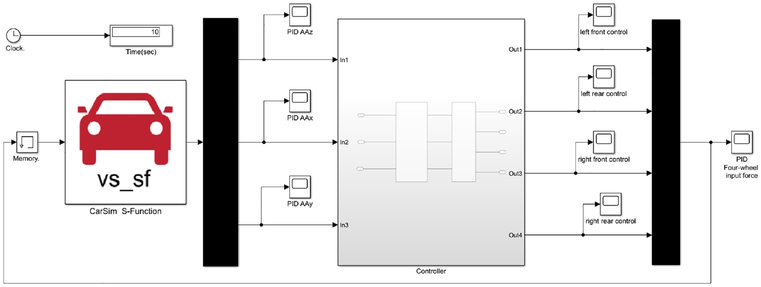
Closed-loop co-simulation model diagram.
Co-simulation results and analysis
With the same random road surface as input, the active suspension system with the designed PID controller is simulated and compared with the passive suspension system at speeds of 70, 90, and 120 km/h. The evaluation indicators are chosen as the vertical acceleration, pitch angle acceleration, roll angle acceleration, suspension dynamic travel and tire dynamic load. Then, the influence of the designed PID controller on improving the performance of the active suspension system of the SUV is analyzed.
At the speed of 70 km/h, the performance index comparison between the active suspension system based on the designed PID controller and the passive suspension system is shown in Figures 13 to 17. Among them, Figures 13 and 14 are the comparison of pitch acceleration and roll acceleration of the SUV vehicle at 70 km/h. Figure 15 is the comparison of the vertical acceleration of the vehicle body, where the “blue line” is the performance index simulation curve of the active suspension system based on the designed PID controller, and the “red line” is the performance index simulation curve of the passive suspension system. The contact effect between the tire and the ground can be further judged by the four tire dynamic loads. The time domain response comparison of tire dynamic load is shown in Figure 16. Due to the requirement of mechanical stiffness, the dynamic travel of the active suspension system of the SUV vehicle cannot exceed the maximum limit of −80 and 95 mm. The comparison of the suspension dynamic travel time domain response at 70 km/h is shown in Figure 17.
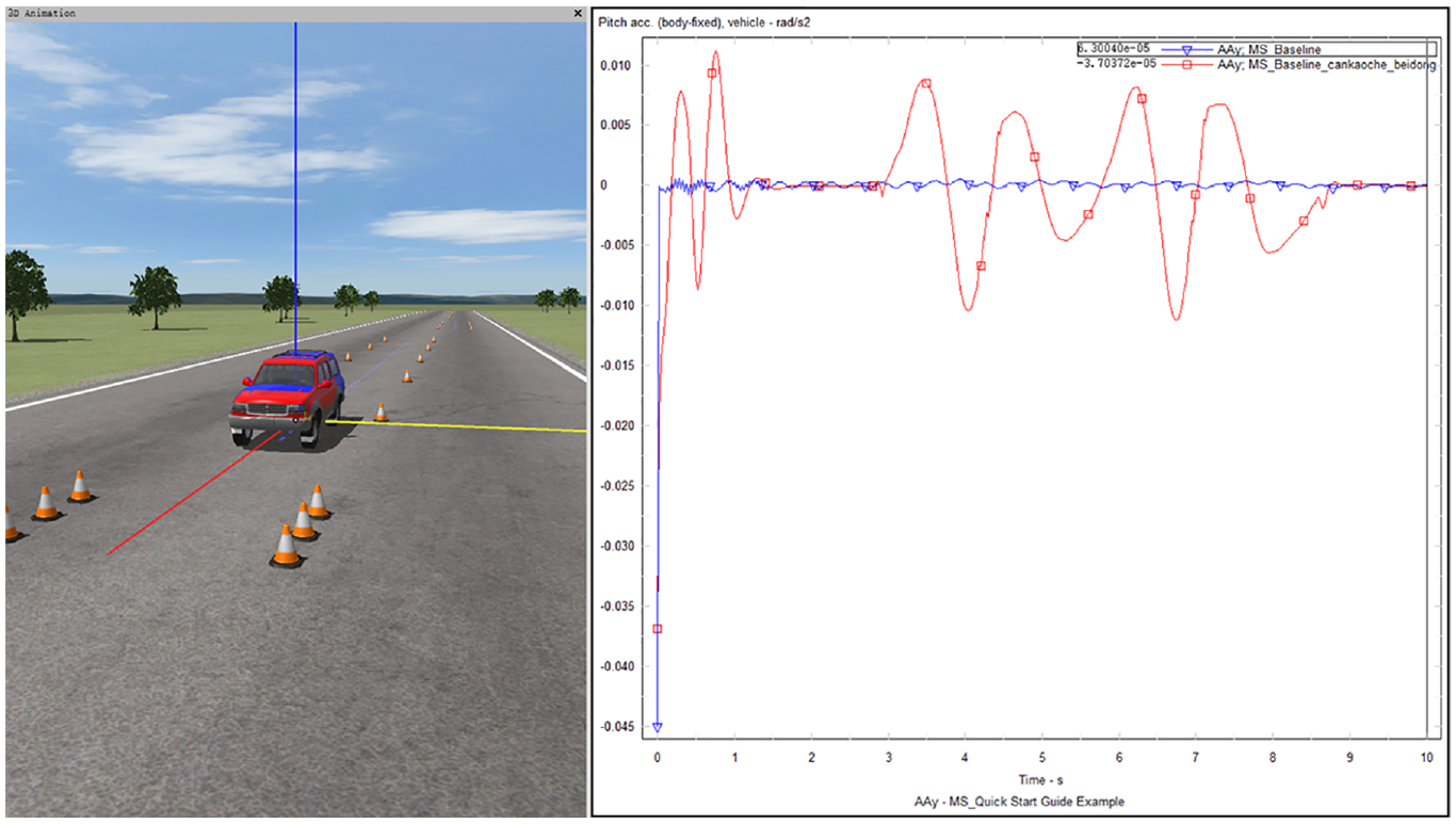
Comparison of the simulation results of the body pitch acceleration.
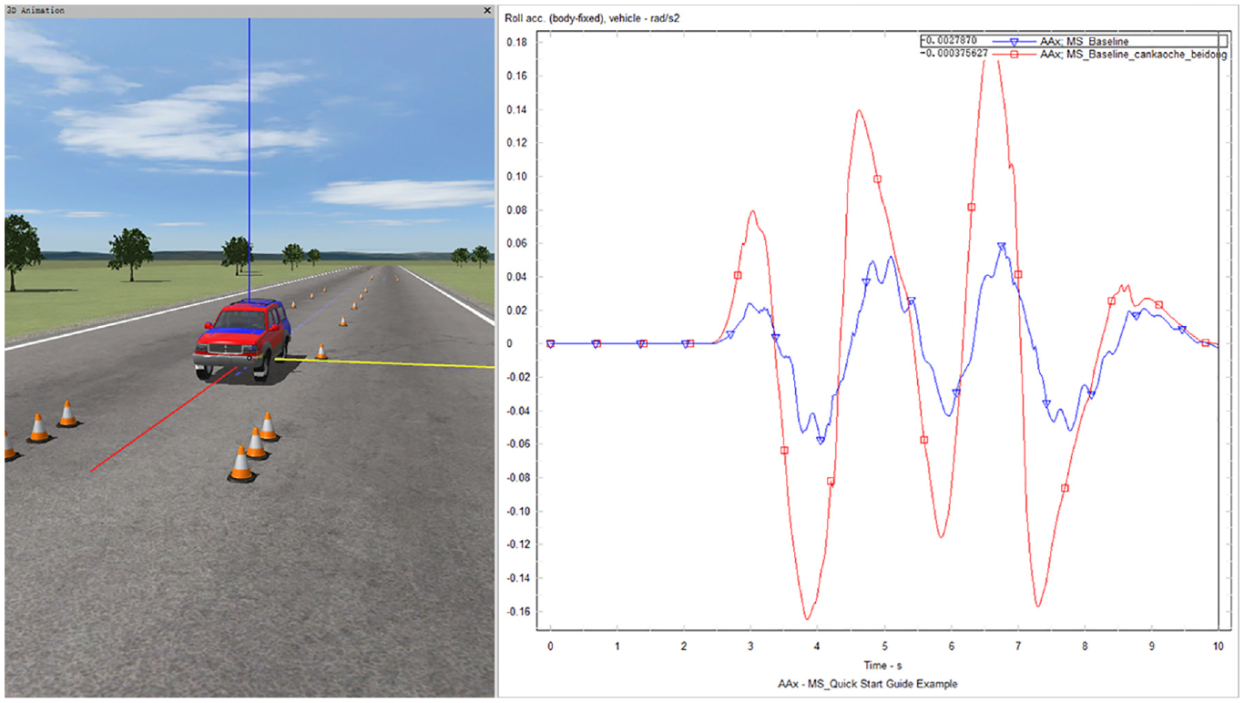
Comparison of the simulation results of the body roll angle acceleration.
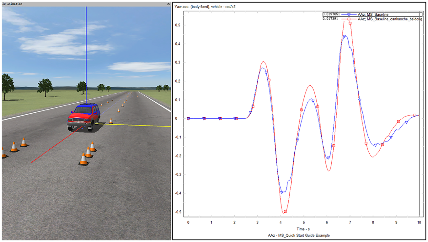
Comparison of the simulation results of the vertical acceleration of the vehicle body.
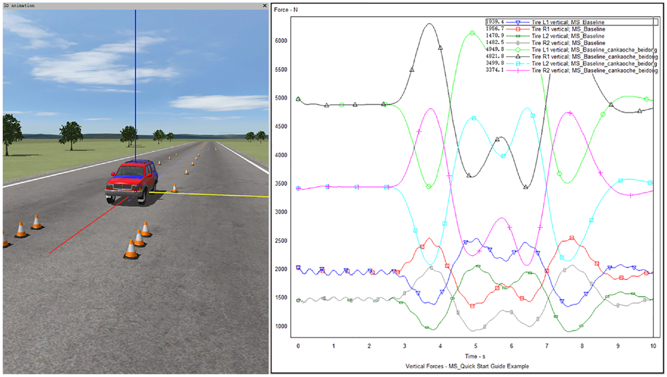
Time domain response comparison diagram of front and rear tire dynamic load.
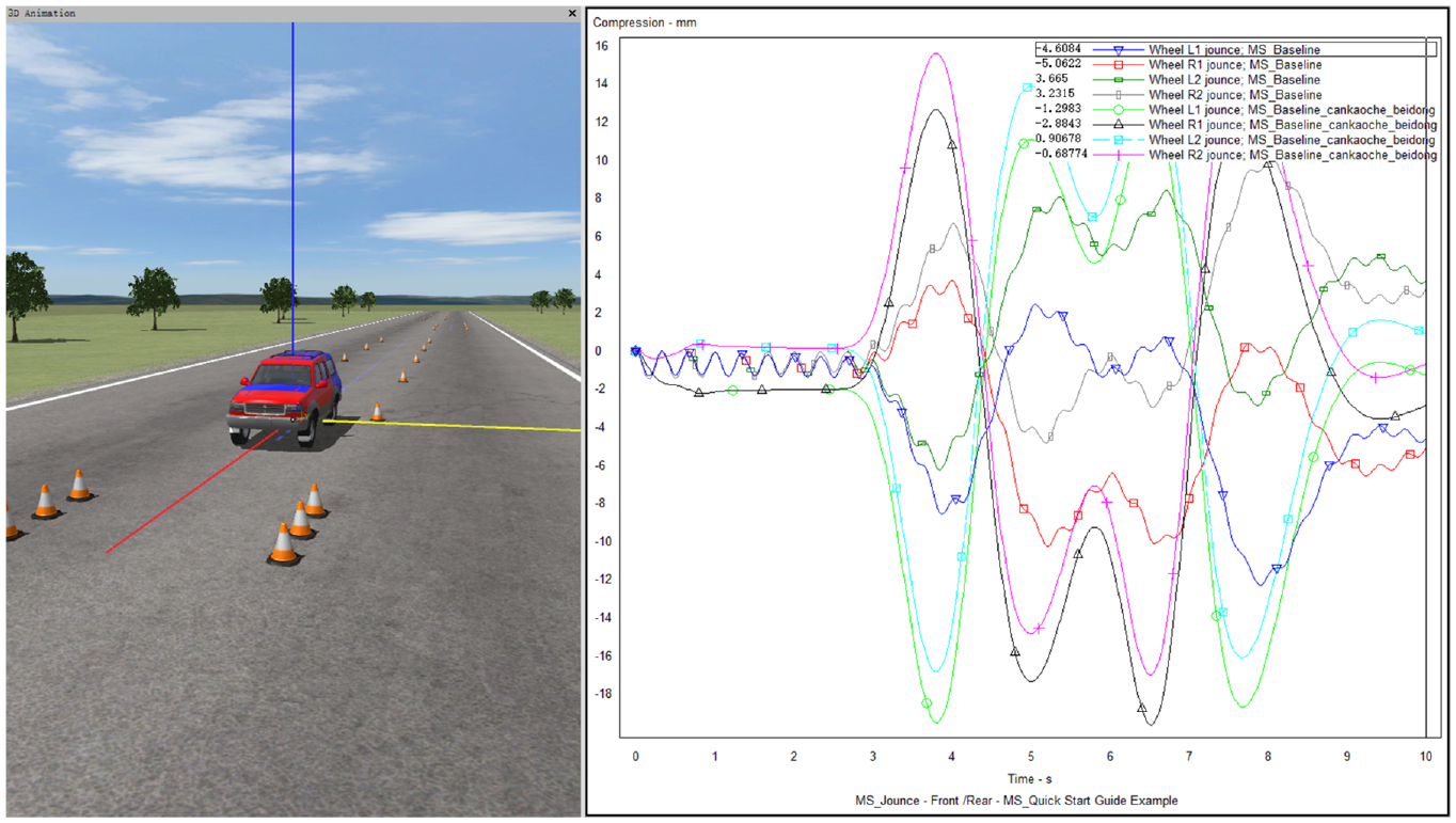
Time domain response comparison chart of front and rear suspension dynamic travel.
Among them, the evaluation index RMS value comparison of the active suspension system based on the designed PID controller and passive suspension system at the speed of 70 km/h is shown in Table 3.
Comparison of the RMS value of the evaluation index between the active suspension system and the passive suspension system of the SUV at 70 km/h.
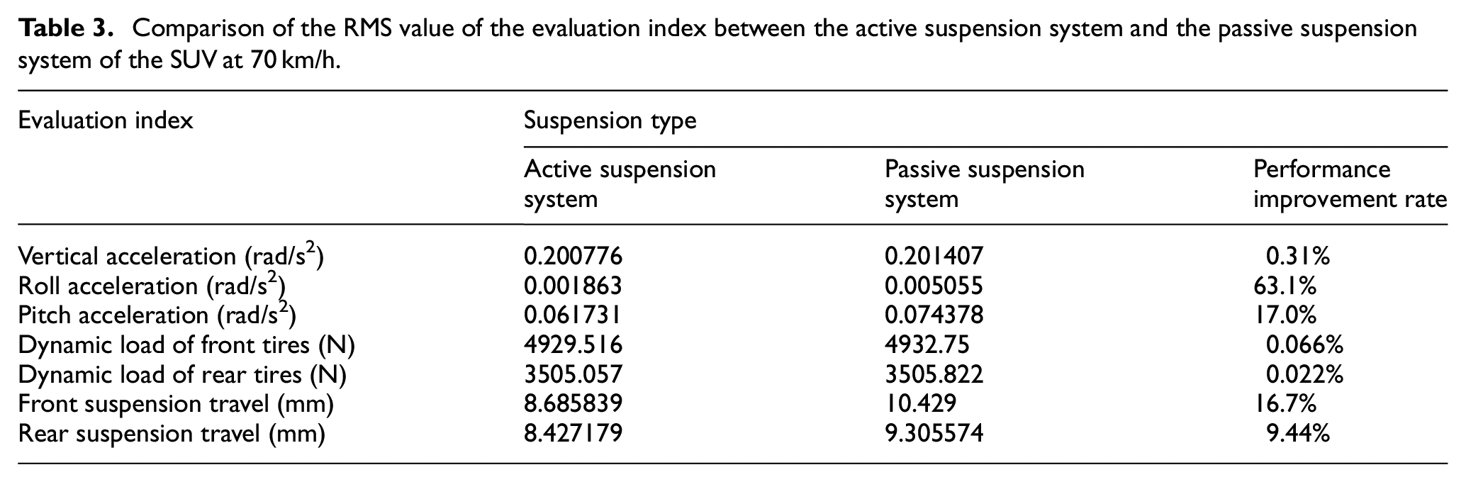
It can be seen that the body acceleration (body vertical acceleration, pitch acceleration and roll acceleration) in Figures 13 to 15 and the performance improvement rate of the RMS value of the corresponding evaluation index in Table 3. When the active suspension system based on PID controller is at a speed of 70 km/h, the acceleration of the vehicle body can be greatly reduced, and the driving safety and riding comfort of the vehicle can be significantly improved. According to the comparison of tire dynamic load time domain response and front and rear suspension system dynamic travel time domain response in Figures 16 and 17 and the RMS performance improvement ratio of the corresponding index in Table 3. It can be seen that the active suspension system based on PID control can not only enhance the contact effect between the tire and the ground, but also further improve the suspension travel within the standard range. Therefore, the designed PID controller can improve the overall performance of the vehicle when the speed is 70 km/h.
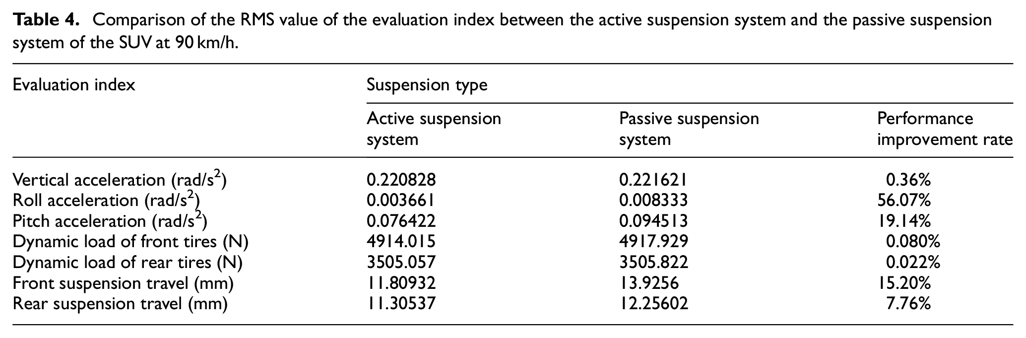
Under the same other conditions, with reference to the comparative simulation analysis of the vehicle speed at 70 km/h, the active suspension system with the designed PID controller is compared with the passive suspension system at the speeds of 90 and 120 km/h, where Tables 4 and 5 are the RMS value comparisons of the evaluation index between the active suspension system with the designed PID controller and the passive suspension system at 90 and 120 km/h, respectively.
Comparison of the RMS value of the evaluation index between the active suspension system and the passive suspension system of the SUV at 90 km/h.
Comparison of the RMS value of the evaluation index between the active suspension system and the passive suspension system of the SUV at 120 km/h.
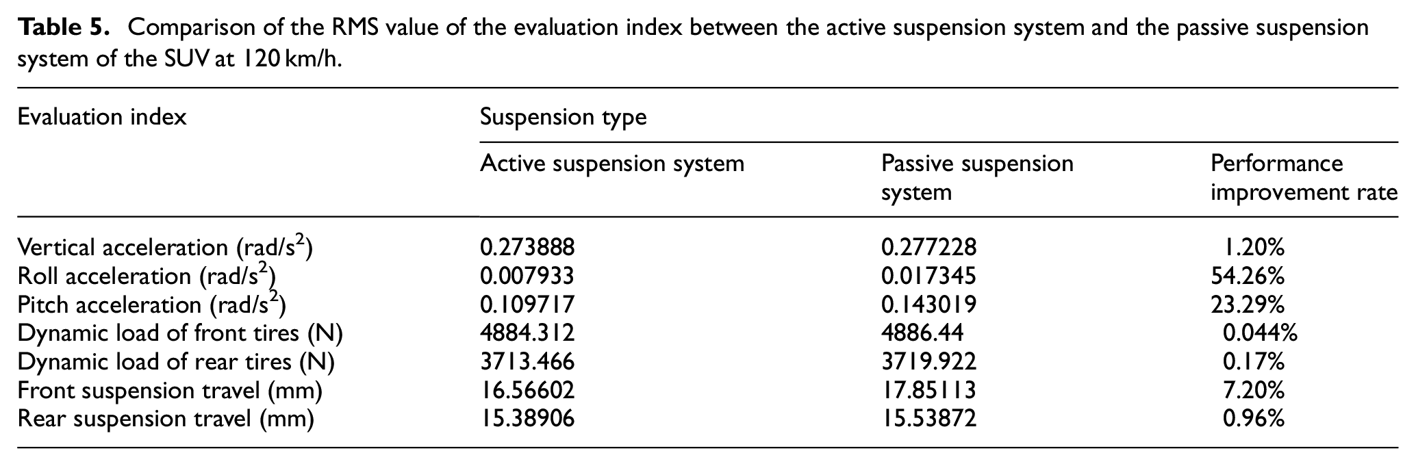
As can be seen from Tables 4 and 5 that at speeds of 90 and 120 km/h, the active suspension system based on PID controller can significantly improve the performance indicators such as body acceleration, tire dynamic load, and suspension dynamic travel. Then, the driving safety and ride comfort of the vehicle can be improved on the random roads.
Conclusion
This paper has investigated the active suspension of a seven-degree-of-freedom SUV vehicle, the body acceleration, tire dynamic load and suspension dynamic travel are taken as the performance evaluation indexes of the active suspension. Based on the advantages of modeling the real vehicle suspension system in Carsim, a closed-loop co-simulation of a seven-degree-of-freedom vehicle active suspension system and a PID controller have been proposed, and the influence of the designed PID controller on the active suspension have been studied. From the comparison of the RMS values of the corresponding evaluation index between the active suspension system and the passive suspension system, it can be seen that the designed PID controller can significantly improve the overall performance of the vehicle at different speeds. Thereby improving the driving safety and riding comfort of 7-DOF SUV vehicles.
Footnotes
Declaration of conflicting interests
The author(s) declared no potential conflicts of interest with respect to the research, authorship, and/or publication of this article.
Funding
The author(s) disclosed receipt of the following financial support for the research, authorship, and/or publication of this article: This work was supported by National Natural Science Foundation of China (U22A2043).