
Abstract
Considering the difficulty in setting and observing the flux linkage in the existing direct torque control for the brushless direct current motor, which is the cumbersome torque calculation method in direct torque control systems without flux linkage observation, the torque observation, voltage vector selection, and speed loop were studied further in such systems. The fuzzy proportional–integral–derivative direct torque control strategy is presented without flux linkage observation. In terms of torque observation, the cumbersome counter electromotive force calculation method was abandoned, and observation was made combining the three-phase current and Hall signal. In terms of optimal choice of voltage vector, the voltage vector selection table was built using the voltage hysteresis output and Hall signal. In terms of rotation speed control, the adaptive fuzzy proportional–integral–derivative was used to replace the traditional proportional–integral–derivative for the proportional–integral–derivative parameter self-adjustment. A control system simulation model was set up in MATLAB/Simulink for simulation verification. A hardware experimental platform was set up using DSP2812 as the main control board for experimental verification. The research results show that the fuzzy proportional–integral–derivative direct torque control without flux linkage observation further increased the dynamic response rate of the motor speed and reduced the electromagnetic torque ripple amplitude; thus, it is more suitable for application in high-precision and high-stability systems.
Keywords
Introduction
Brushless direct current motor (BLDCM) has been widely used in industry, transportation, and other fields due to its simple structure, high power density, high torque–current ratio, high efficiency, and good speed regulation performance. However, the nonideal trapezoidal wave back EMF, nonideal square wave current, stator cogging torque, and air gap magnetic field distortion caused by armature reaction and other factors make the torque ripple of the BLDCM more obvious, thereby affecting further improvement of its performance and limiting its application in high-precision, high-stability systems. To suppress the torque ripple and improve the dynamic response performance of the torque, many scholars have introduced the idea of direct torque control (DTC) into the control of BLDCM to expand its application in high-precision servo systems such as industrial robots and aerospace controllers. 1 –3
At present, the DTC method is widely applied to the BLDCM to suppress the torque ripple and improve the dynamic response of the electromagnetic torque. 4,5 Facts also prove that the DTC is a highly effective control strategy that directly acts on the BLDCM output torque. 6,7
The traditional DTC is composed of a torque and flux double loop. The control strategy is as follows: the voltage vector is selected based on the output of the torque hysteresis loop and flux hysteresis loop; the nonzero voltage vectors are defined by two nonzero digits; and the zero voltage vectors are defined by all-zero digits. 8,9 This strategy demands a series of transformations and calculations to achieve real-time observation and real-time control of the flux linkage and torque.
In Xia et al., 10 the DTC of BLDCM was achieved using this method, although there is a larger ripple in the output electromagnetic torque. In Wang et al., 11 based on the torque and flux double loop control, the voltage vector acting time was adjusted using the fuzzy control rules, and the zero-voltage vector defined by all-zero digits was used to decrease the torque, which reduced the torque ripple to a certain extent.
In Yang and Hu, 12 the targeting difficulties of the traditional DTC were demonstrated for the flux linkage observation and determination. The flux linkage observation was omitted. The optimal nonzero voltage vector was selected based on the relationship between the rotor position and the torque hysteresis output τ to realize the motor DTC, which did not use all-zero vectors when decreasing the motor torque. Instead, it was adopted to increase the inverse vector of nonzero voltage vectors.
The study in An et al. 13 proposed a flux linkage self-control DTC scheme and observed the back-EMF using a synovial observer to calculate the torque, which could effectively suppress the torque ripple under nonideal back-EMF and low speeds, but the torque ripple effect was not ideal during the high-speed motor operation.
The study in Nair et al. 14 proposed a DTC method based on the duty cycle adjustment of the effective voltage vector and zero vector action time. The phase current and torque ripple are reduced in the method, but it is cumbersome to calculate the electromagnetic torque and duty cycle.
In Zhu et al., 15 based on the traditional DTC, the segmented sliding mode variable structure state reconstruction method was used to observe the back-EMF. Although the rapidity and robustness of the system are improved, the control method requires the establishment of a complicated back-EMF state observer to calculate the electromagnetic torque, and the flux link is involved in the torque control, which makes the system structure too complicated.
In this article, based on the previous research on the DTC strategy without flux linkage observation for BLDCM, new explorations were made. The fuzzy proportional–integral–derivative (PID) DTC strategy without flux linkage observation was proposed: in terms of the rotation speed control, the adaptive fuzzy PID control algorithm was used to accurately control the rotation speed. In terms of torque control, the phase current and Hall signal were combined to observe the torque. The torque regulator and Hall signal were combined to select the optimal voltage vector for real-time torque control. Based on the aforementioned control strategy, the corresponding control system simulation model was built using the MATLAB/Simulink software to simulate the rotation speed and torque control, and a hardware experiment platform was built using the DSP2812 control board to experimentally verify the system control effect. Both simulation and experimental results confirm the good rotation speed and torque control effects of the control system.
Fuzzy PID DTC strategy without flux linkage observation
Considering the deficiencies of the traditional DTC control system in the motor flux linkage determination and estimation and the complicated process in torque acquisition, 13,16 this article proposes a fuzzy PID DTC strategy without flux linkage observation; the control strategy block diagram is shown in Figure 1. The flux linkage observation and adjustment module is omitted in the strategy, which is only composed of the outer ring of rotation speed and the inner ring of torque. The principle is that the motor speed is detected using the BLDCM Hall sensor; the speed error and speed error rate of change are provided as inputs to the fuzzy controller by the speed loop using the adaptive fuzzy PID control method, and the output is a given torque value.

Block diagram of the fuzzy PID DTC strategy without the flux linkage observation. DTC: direct torque control.
Since it is impossible to directly obtain a trapezoidal back-EMF of BLDCM, it is relatively cumbersome to calculate the electromagnetic torque using the back-EMF method. This article calculates the electromagnetic torque amplitude of the motor using a three-phase current according to the generation principle of the motor electromagnetic torque. The electromagnetic torque direction was determined using the three-way Hall sensor signal. The electromagnetic torque calculated by the phase current was compared with the given torque value output by the fuzzy PID speed regulator. Then, the optimal voltage vector was selected based on the torque regulator output value and Hall signal to directly control the motor electromagnetic torque.
Electromagnetic torque observation
In the DTC control system, the electromagnetic torque observation plays a very important role, which directly affects the control effect of the control system over the motor torque ripple. The BLDCM electromagnetic torque is calculated as 17 –19
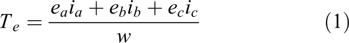
where ex and ix are the motor back-EMF and phase current, respectively; w is the motor mechanical angular velocity; and x can be a, b, c.
The real-time observation of the motor electromagnetic torque using the above formula mainly relies on the estimation accuracy of the motor back-EMF value. Since it is difficult for the motor to form a trapezoidal wave back-EMF with a flat top width of 120° in the actual design and manufacturing process, electromagnetic torque ripple will occur if this method is used. In this article, the relationship between the three-phase current and the electromagnetic torque amplitude is obtained per unit processing of the motor back-EMF, as shown in Figure 2. Figure 2 shows the relationship between the Hall sensor signal and the motor back-EMF shape function, which is the current in an electrical cycle. The motor three-phase back-EMF per unit processing is expressed as 20

where ke
is the back-EMF coefficient of the motor; n is the motor speed;

Relationship between the Hall sensor signal and the motor back-EMF shape function current.
The electromagnetic torque amplitude can be obtained by combining formulas (1) and (2) and kt = 2ke

where Ts is the electromagnetic torque amplitude and kt is the torque constant.
According to the waveform in Figure 2, by analyzing the relationship between each phase back-EMF shape function, current waveform, and Hall sensor output signal, we can deduce the electromagnetic torque symbol expression during the motor forward rotation. The motor working principle indicates that the electromagnetic torques during the motor forward and reverse rotation are opposites of each other, so the electromagnetic torque is expressed as

where Tz
is the electromagnetic torque symbol; sign(x) is a sign function;
In summary, the electromagnetic torque calculation formula for the motor is:

Formula (5) shows the electromagnetic torque calculation formula. With the formula, only by acquiring the Hall sensor output signal and three-phase current value, the electromagnetic torque amplitude and direction can be observed in real time without the need to know the motor back-EMF value and rotor position information, which further simplifies the DTC control system.
According to the difficulty of obtaining the variables and parameters required by formulas (1) and (5), the proposed method, which combines the Hall signal with the phase current, can effectively simplify the design of the control system compared with the method proposed in references 17 –19 and avoid the fluctuation of electromagnetic torque caused by errors in the manufacture of the motor structure, which can be regarded as having certain robustness.
Space voltage vector selection
In the BLDCM DTC technology, the voltage vector constitutes an extremely important physical variable as the original driving force of the DTC system. Hence, how to select the optimal space voltage vector during the motor operation is the primary problem to be solved. The space voltage vector is usually represented by six digits. 21,22 As shown in Figure 3, 0 and 1 are used to indicate the turn-on and turn-off state of the power tubes. Each power tube corresponds to a state. BLDCM usually uses the two-phase conduction three-phase six-state full-bridge drive mode. The three-bridge arm inverter provides eight states, including six valid states of V1 (100001), V2 (001001), V3 (011000), V4 (010010), V5 (000110), and V6 (100100). In this article, V0 (000000) is used as the “public voltage anti-vector,” which can reduce the electromagnetic torque. Since the switching states of the two conducting phases of the inverter at each moment are in a one-to-one correspondence with the voltage vectors in the motor, the inverter valid state can also be used to represent the motor space voltage vector. According to Figure 3, the six space voltage vectors divide the space into six equal sectors.
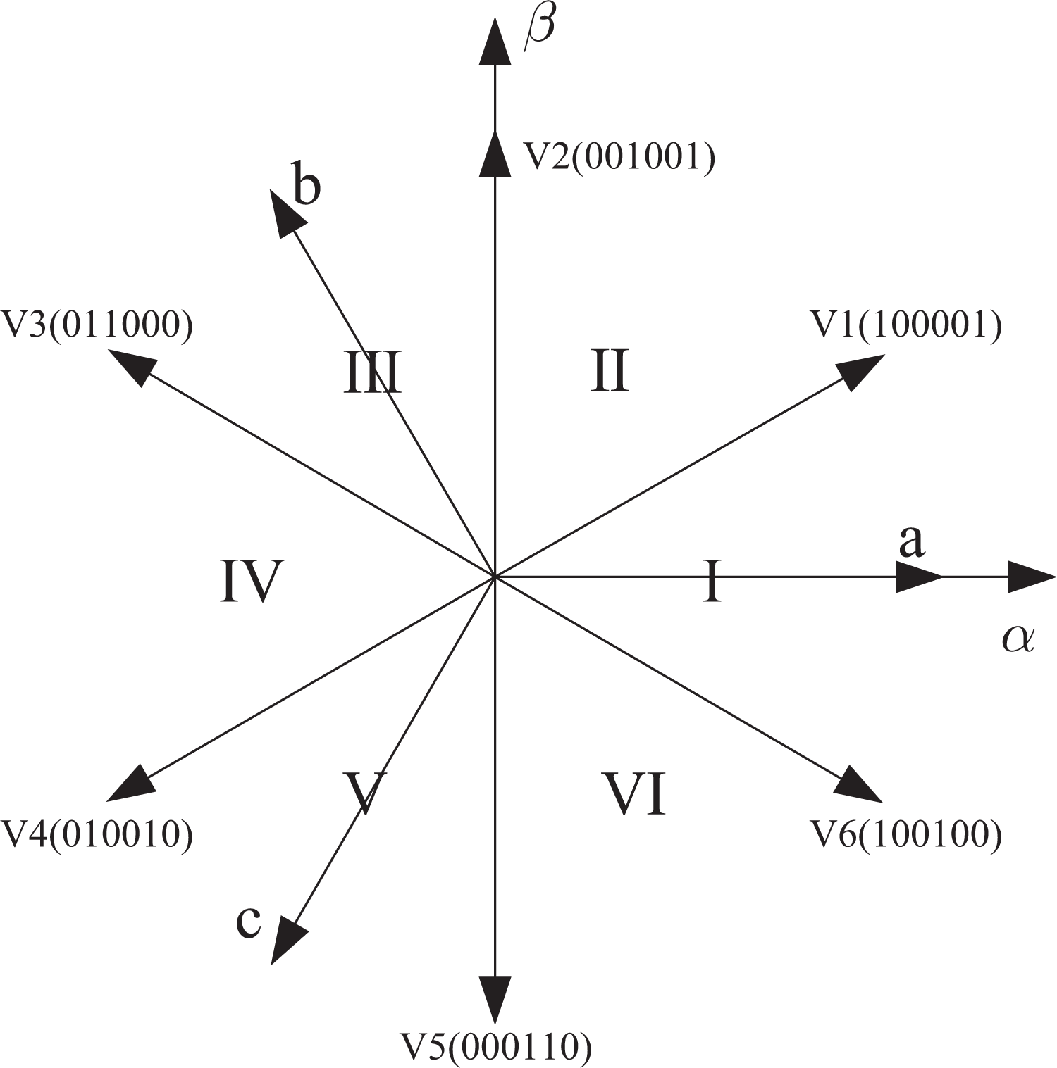
Space voltage vector sector.
The traditional DTC system space voltage vector is selected based on the torque regulator output, hysteresis loop output of the flux linkage, and motor rotor position. The space voltage vector selection table in this article is shown in Table 1. Table 1 shows that the sector where the motor rotor is located is in a one-to-one correspondence with the Hall signal. Therefore, the optimal space voltage vector can be selected at the current position using the Hall sensor output signal and torque regulator output τ.
Space voltage vector selection table.

Design of the adaptive fuzzy PID speed controller
To reduce the effect of the speed fluctuation on the motor electromagnetic torque, this article uses an adaptive fuzzy PID control algorithm for the speed loop to automatically adjust the PID parameters Kp , ki , and Kd according to the fuzzy control principle, so that the entire system control performance can be improved. Since the differentiation element in the PID controller is vulnerable to the interference of external factors, which affects the control system, the differentiation element is abandoned in the controller. The proposed adaptive fuzzy PID control algorithm is shown in Figure 4.

Block diagram of the adaptive fuzzy PID control algorithm. PID: proportional–integral–derivative.
According to Figure 4, the adaptive fuzzy PID speed controller is a two-input two-output structure. The two controller inputs are speed error e and speed error rate of change ec; the two outputs are PID parameter adjustment values
First, e, ec,
Second, the input and output are subject to the fuzzy inference after fuzzy processing. The
Adjustment rule table of

Adjustment rule table of

Finally, the fuzzy control variable obtained through the fuzzy control rule is converted into an actual accurate digital variable, which is a process of defuzzification of the fuzzy control variable.
25
In this article, each fuzzy variable was defuzzified using the median method. After the above series of operations, the obtained adjustment values
Control simulation and experimental verification
Based on the above research and analysis, the control system simulation model is built in MATLAB/Simulink as shown in Figure 5. The model mainly consists of the inverter, BLDCM, adaptive fuzzy PID, torque calculation, torque hysteresis, and voltage vector selection modules. The BLDCM model is a brushless DC motor model in the Simulink software. The parameters are set according to the actually studied target motor: rated voltage 48 v; rated speed 1200 RPM; rated torque 4 Nm; armature winding resistance 0.086 Ω; armature winding inductance 0.787 mH; moment of inertia 2.46e-4 kgm2; and torque constant 0.09 V/RPM.

Control system simulation model.
Simulation condition 1: At speed n = 1000 r/min, the adaptive fuzzy PID DTC and traditional PID DTC speed simulation waveforms of the motor during forward and reverse rotations and the difference between the actual speed and the given speed under no-load conditions are shown in Figures 6 to 9. The comparison of the waveforms in Figures 6 and 8 reveals that the adaptive fuzzy PID DTC can reach the given speed value faster than the ordinary PID DTC control regardless of whether the motor is rotating forward or reverse, which improves the motor speed response performance. The comparison of the waveforms in Figures 7 and 9 reveals that the adaptive fuzzy PID DTC can better reduce speed fluctuation than the ordinary PID DTC whether the motor is forward or reverse.

Simulation waveform of the motor forward speed under no load.

Difference in motor forward speed between the actual speed and the given speed under no load.

Simulation waveform of the motor reverse speed under no load.

Difference in motor reverse speed between the actual speed and the given speed under no load.
Simulation condition 2: The adaptive fuzzy PID DTC and traditional PID DTC torque control simulation waveforms of the motor are shown in Figures 11 and 12 under the change in motor load as shown in Figure 10. The comparison of waveforms in Figures 11 and 12 reveal that adaptive fuzzy PID DTC has better torque tracking and torque ripple suppression than the ordinary PID DTC, where the torque tracking improved by nearly 8%, and the torque ripple reduced by nearly 10%.

Change of motor load.
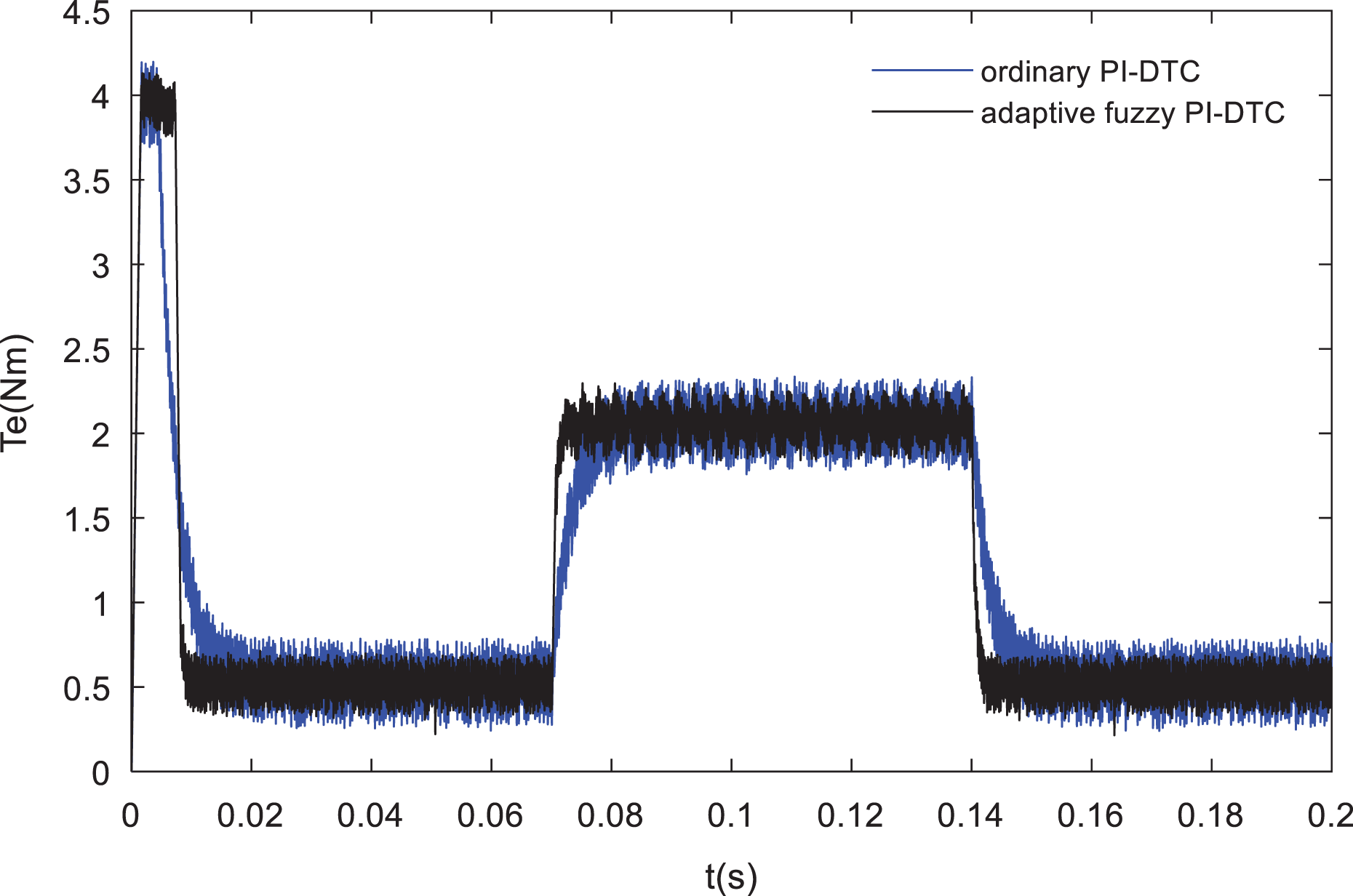
Torque simulation waveform during the motor forward rotation.

Torque simulation waveform during the motor reverse rotation.
The simulation results show that the adaptive fuzzy PID control system has faster speed response and more effective suppression of the torque ripple.
Experimental verification: The target BLDCM with consistent parameters with the simulation ones is used to verify the simulation conclusion. The hardware experimental platform is built for the DTC control system without flux linkage observation as shown in Figure 13. Using this experimental platform, the speed experiment waveforms of the motor is measured under the adaptive fuzzy PID DTC control without flux linkage observation in the no-load condition, as shown in Figures 14 and 15.

Control system hardware experiment platform.

Motor speed experimental waveform of the adaptive fuzzy PID DTC under no load. PID: proportional–integral–derivative; DTC: direct torque control.

Motor speed experimental waveform of the traditional PID DTC under no load. PID: proportional–integral–derivative; DTC: direct torque control.
Figures 14 and 15 show that the motor reaches the given speed value in a very short time with very small speed fluctuation.
The adaptive fuzzy PID DTC and traditional PID DTC torque control experiment waveforms of the motor are shown in Figures 16 and 17 under the change in motor load as shown in Figure 13. The comparison of waveforms in Figures 16 and 17 reveals that adaptive fuzzy PID DTC has better torque tracking and smaller torque ripple than the ordinary PID DTC.

Torque experimental waveform of the adaptive fuzzy PID DTC. PID: proportional–integral–derivative; DTC: direct torque control.

Torque experiment waveform of the traditional PID DTC. PID: proportional–integral–derivative; DTC: direct torque control.
The experiment waveform is consistent with the simulation value; only the fluctuation range of experiment value is larger than that of the simulation one because the actual parameters and simulation parameters of the motor are not exactly identical. The result shows that the control strategy proposed in this article is effective, and the simulation method is correct.
Conclusion
Based on previous research on the DTC system without the flux linkage observation, the fuzzy PID DTC strategy without flux linkage observation was proposed for BLDCM to simplify the system structure, improve the speed response, and decrease the torque ripple. The good effect of this control strategy on the motor speed and torque control was verified using simulation and experimental methods, as demonstrated in the effectively improved dynamic response performance of the motor speed and torque, whereas the ripple of the motor speed and electromagnetic torque was inhibited. The research results have certain reference and practical application value for the DTC control of BLDCM. With the improvement in control accuracy of the permanent magnet BLDCM, it will be widely used in precision instruments, CNC machine tools, aerospace, industrial robots, and other fields with high requirements. The key technologies of the sensorless BLDCM remain the focus of future research.
Footnotes
Declaration of conflicting interests
The author(s) declared no potential conflicts of interest with respect to the research, authorship, and/or publication of this article.
Funding
The author(s) disclosed receipt of the following financial support for the research, authorship, and/or publication of this article: This work was financially supported by the National Natural Science Foundation of China (Grant No. 51575001,51605003), Anhui province science and technology research key project (Grant No. 1604a0902158), of Anhui university scientific research platform innovation team building projects (2016–2018), and Anhui Polytechnic University Young and middle-aged top-notch talent project (2016BJRC010).