
Abstract
This paper presents application of the combination of mapping, image identification, and indoor navigation for the omnidirectional wheeled mobile robot (WMR). The mapping part uses the point clouds converted from the depth map of the LiDAR camera to construct the indoor 3D point cloud map. Combining this map with the You Only Look Once ver.4 (YOLOv4) network, the door number and the doorknob can be displayed on the map by image identification. The navigation part applies 3D point cloud map, image, and depth map to an omnidirectional WMR so that it can know the current position and plan the path to the designated location. The proposed control scheme can make the robot perform indoor navigation and reach designated location.
Introduction
Because of the advancement of technology makes modern people more convenient, many simple or laborious works can be handed over to smart phones, computers, and even intelligent robots to achieve the goal of reducing human cost, for instance, patrol task, the work of security guard is simple but time consuming. As a consequence, intelligent robots are surely competent to do the patrol. Due to the development of artificial intelligence (AI) the research of intelligent robot control is widely discussed. How to navigate indoor for intelligent robots is an important topic in robotic research. Indoor navigation has been studied for years it includes path planning, trajectory tracking, and obstacle avoidance. Among these studies, image processing provides valuable solution to locate position and avoid obstacle. Chang et al. 1 proposed a neural network that imitates the cone cells of human eyes. A single RGB image is divided into four pieces and each image corresponds to one network. They called it the merged convolution neural network (CNN) and utilized it and a monocular webcam to avoid obstacles. 1 Xue et al. designed the special action space and efficient reward function on Deep Double Q-Learning (DDQN) to collision avoidance, and the multiple obstacles scenarios are extended from the one-obstacle network based on the voting mechanism. 2 Fu et al. 3 presented deep ordinal regression network (DORN) to achieve estimating depth from 2D images, and it could be used on obstacle avoidance. Gong et al. used visual location method based on beeline detection to locate the indoor mobile robot. 4 Although the method is simple, positioning error is less than 5 cm. Wang et al. detected positions of the dummy boxes with ArUco markers by camera at bird’s view, then navigate mobile robot by multi-objective evolutionary algorithm (MOEA). 5 Pambudi et al. 6 designed the fuzzy Q-Learning (FQL) algorithm to navigate mobile robot to reach the target and avoid dynamic obstacle. Kim et al. 7 proposed combining information of vision marker in the image with data from laser scanner to obtain position of robot. Wang et al. 8 utilized Gmapping, Augmented Monte Carlo Localization (AMCL), and improved A* algorithm to achieve mapping, localization, and path planning for robot, respectively. Although the above methods effectively achieve robot control, this study is mainly inspired by the following two papers. Ma et al. 9 constructed the 3D point cloud map through RGB-D simultaneous location and mapping (SLAM) by the KinectV2 and established the mapping relation between 3D points and 2D image feature points in offline stage. Then estimate the position of user by efficient perspective-n-point (EPnP) algorithm. 9 Maolanon et al. 10 improved SLAM algorithm with furniture detection CNN network so as to increase ability of robot. It combines mapping with object detection to let robot know where it is and which room it is in. YOLOv3 tiny was chosen to the CNN detector. 10
Since the experiment of this study is carried out in the indoor space, an omnidirectional wheel mobile robot (WMR) is selected. Comparing the omnidirectional WMR to the ordinary moving robots, the omnidirectional WMR has more actions like right shift and left shift. Therefore, the omnidirectional WMR has the ability to move in a narrow and complex environment, such as indoor.11,12 The traditional robots have a number of sensors to avoid obstacle and navigate movement, such as ultrasonic 13 and laser sensors 14 for obstacle avoidance, StarGazer 15 and RFID 16 for positioning and navigating. How to navigate mobile robots has always been one of the issues of robotic research. For outdoor navigation, GPS/INS 17 or RTK GNSS 18 are used as method of precise location, but the signal will be blocked and resulting in poor effect when the robot is inside a construction. There are several ways in indoor navigation, such as Beeline Detection, 4 Multi-Objective Evolutionary Algorithm (MOEA), 5 Fuzzy Q-Learning, 6 and Scale-Invariant Feature Transform (SIFT). 19 These methods have a good performance in indoor navigation, but also have some disadvantages. The first method can only be achieved in a place with obvious tile gaps; the second method needs an additional camera to show the whole domain, and all obstacles must be pasted ArUco markers before being identified; third method and fourth method need a quantity of calculations to achieve. In here, we combine 3D point cloud with object detection algorithm You Only Look Once ver.4 (YOLOv4) 20 to build a 3D point cloud map and using this map with YOLOv4 to achieve indoor navigation. In this study, only one camera is used with less computing time which is good for real time operation.
System description
In this study, first of all, the objects of feature points in the environment of omnidirectional WMR working space must be determined. The objects we choose are doorknobs, doorplates, and room numbers. Secondly, take some pictures of the working space and put them into YOLOv4 for training, then get its weights. Thirdly, combine the LIDAR camera with omnidirectional WMR to 3D mapping. In the process, use the weights that are trained to object identification, then record coordinates of objects, and combine them with the map if it had been recognized. Finally, omnidirectional WMR can use this map to achieve indoor navigation.
The outlook of the omnidirectional WMR used for this study is shown in Figure 1 and the hardware architecture is shown in Figure 2. The upper part is two arms and one head just like human body, the lower part is combined with three omnidirectional wheels. Its head is Intel RealSense LiDAR camera L515 for getting visual and depth, as show in Figure 3(a). The features of this camera are: Depth Capture from 0.25 to 9 m, 2 MP RGB Camera, Inertial Measurement Unit, Up to 30FPS Depth at 1024 × 768, Up to 30FPS Color at 1920 × 1080, and Class 1 Laser Compliant. The DYNAMIXEL 2XC430-W250-T servo motor, which is produced by ROBOTIS Company, can control two axes with a single module. This motor is applied to omnidirectional WMR’s neck for rotating head’s pitch and yaw, as show in Figure 3(b). The control commands are all calculated on the embedded system NVIDIA Jetson AGX Xavier, as show in Figure 3(c). It is installed on a board at back of omnidirectional WMR.
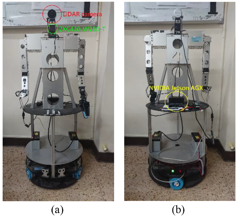
The front (a) and back (b) of the omnidirectional WMR.
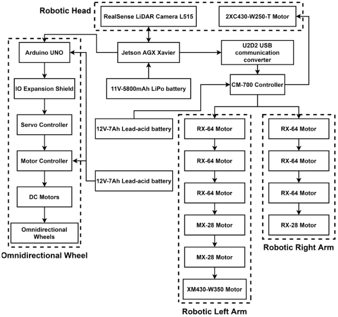
Hardware architecture.
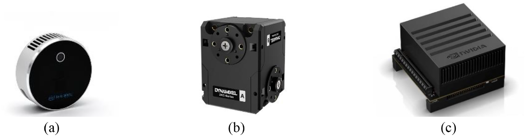
(a) Intel RealSense LiDAR camera L515, (b) DYNAMIXEL 2XC430-W250-T servo motor, and (c) NVIDIA Jetson AGX Xavier.
The Robot Operating System (ROS) is a platform for developing robot functions, and it is utilized for data transfer, execution of shared functions, application management, etc. RViz is a 3D visualization tool for the ROS application that emphasizes the visual display of existing data. We use RViz to display 3D point cloud map, route, and probable location of robot. The system architecture of mapping based on ROS is shown in Figure 4. The realsense info node is responsible for receiving information of LiDAR camera, converting the depth data into point clouds, and publishing information. The head node is utilized for controlling the servo motor of neck and saving point cloud information from topic it subscribes. The wheel record node is the controller of Arduino UNO that control omnidirectional wheel. The Yolo node is responsible for recognizing the object, saving these data, and publishing these images for RViz to show us.
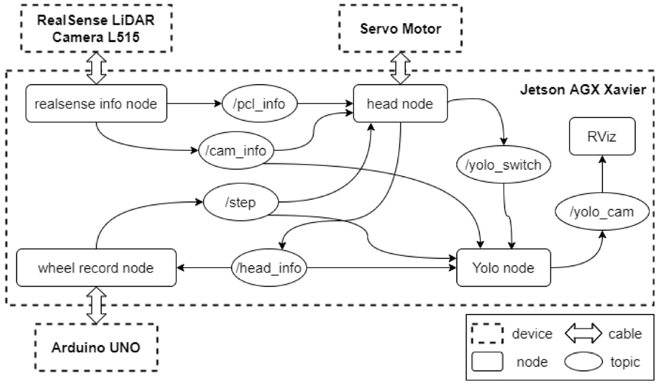
System architecture of mapping.
The architecture of navigation system based on ROS is shown in Figure 5. The function of realsense info node in Figure 5 is just like that in mapping, but point cloud change to depth map and it decides method of obstacle avoidance according to depth information. The path planning node is utilized for publishing 3D point cloud map and position of object for RViz to show us and planning robot’s route according to task that we give. The wheel and motor control node is the controller of the omnidirectional WMR. The yolo detection node is similar to the Yolo node in mapping and it adds function to know distance between robot and object.
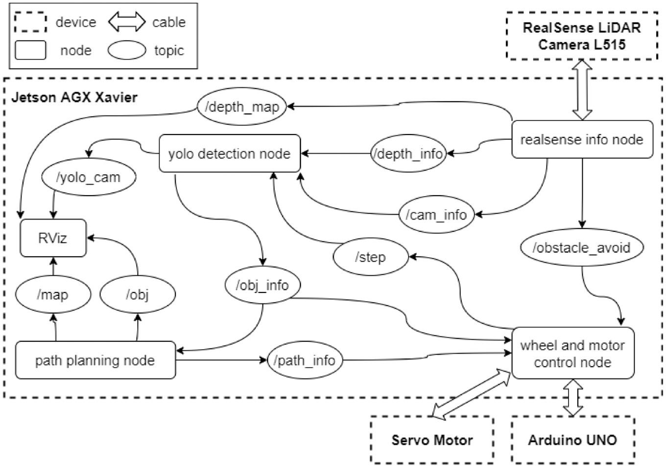
Architecture of navigation system.
Point cloud and map
In order to construct a 3D point cloud map, we must know how to calculate the point cloud in real world coordinate system. First, we need depth map and it can be obtained by the LiDAR camera. Then convert the depth map into point cloud according to pinhole camera model. Finally, a 3D point cloud map is composed of those point clouds. In the computer vision, the depth map is the image or image channel, and it includes the information of distance of scene objects from the viewpoint. We can get every pixel’s distance between camera and scenes by the LiDAR camera, as shown in Figure 6. Depth map is used to calculate the point cloud, obtain the distance between omnidirectional WMR and object which is detected, and avoid the obstacle on the pathway.
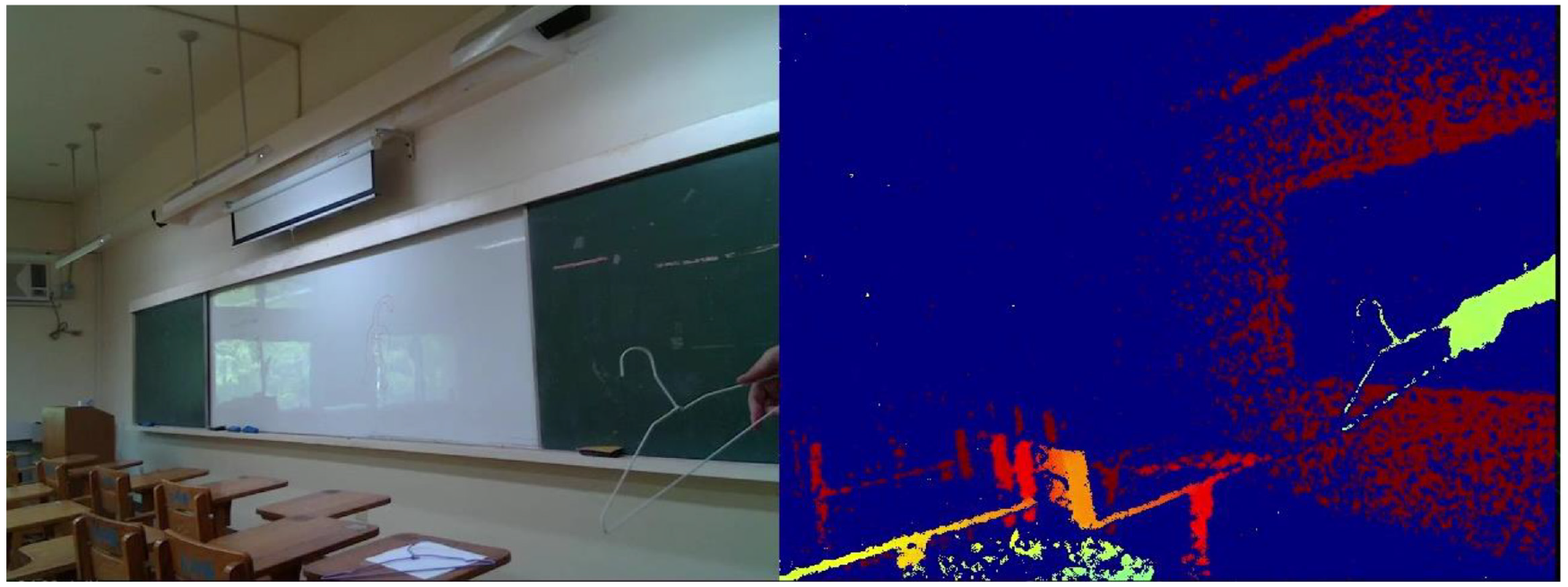
Image of RGB frame and depth frame.
By the theory of pinhole camera model, the coordinates of actual object can be converted to image coordinates. Conversely, we can also convert the two-dimensional image coordinates into three-dimensional real world coordinates. First, the relation between real world coordinate system and camera coordinate system is discussed. As the name suggests, the former is coordinate system in real world and its origin can be set anywhere by user; the latter is coordinate system that origin is the focus of camera. If the origin of real world coordinate system is defined as the focus of camera, this real world coordinate system is equal to the camera coordinate system. In constructing map, the camera on the omnidirectional WMR moves around and the origin on camera coordinate system constantly changes, so the origin of real world coordinate system almost impossible is the focus of camera. The way to convert real world coordinate system into camera coordinate system is simple, just use the extrinsic parameter matrix. The extrinsic parameter matrix is composed of rotation matrix and translation matrix, and it is the 3 × 4 matrix, as shown in equation (1).
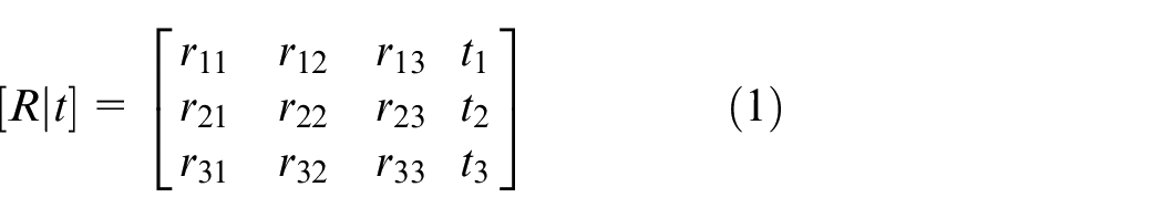
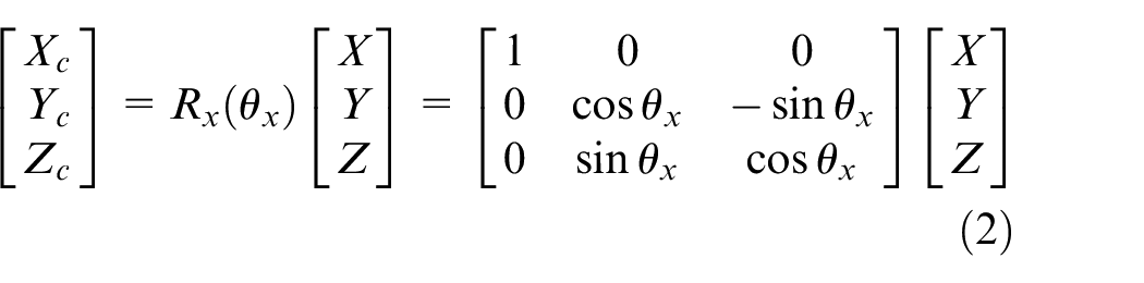
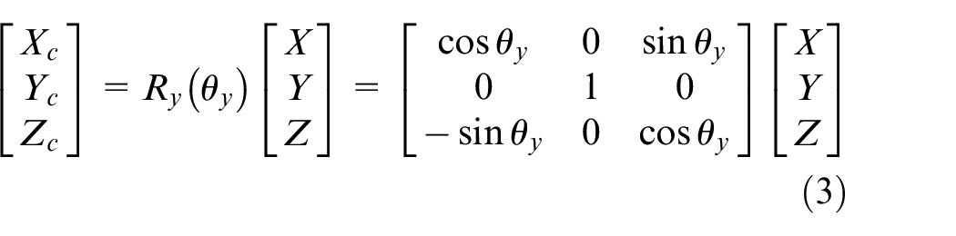
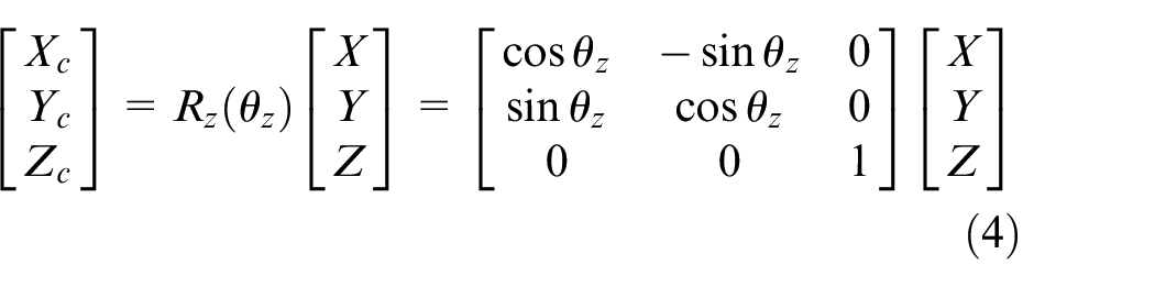
Figure 7 shows the axis of roll, pitch, and yaw. The equations (2)– (4) represent the rotation matrix of roll, pitch, and yaw, also mean that rotate around x-axis, y-axis, and z-axis, respectively. Those are shown in Figures 8–10. Put simply, we utilize this matrix to transform the origin of real world coordinate system into the focus of camera, as shown in Figure 11.
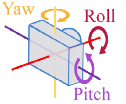
The axis of roll, pitch, and yaw.
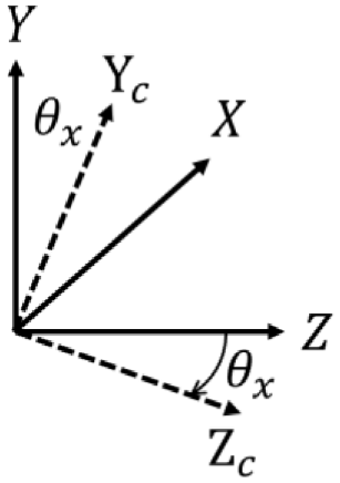
Rotate around x-axis.
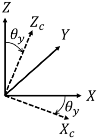
Rotate around y-axis.
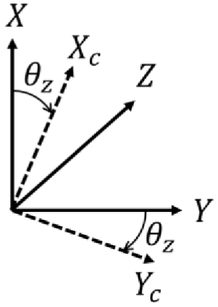
Rotate around z-axis.
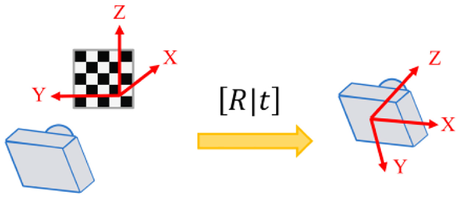
Transformation of real world coordinates.
We can convert real world coordinate system into camera coordinate system. Next part is the relation between camera coordinate system and image coordinate system. Figure 12 shows the camera with center of projection
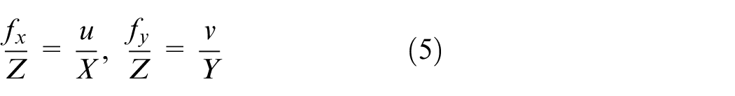
Where
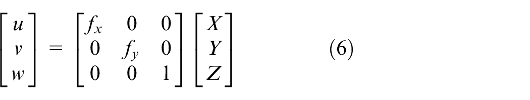
If the origin of the image coordinate system does not coincide with where the
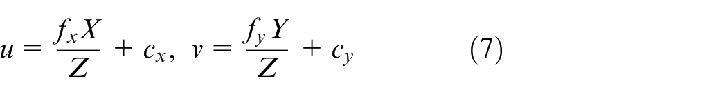
Where
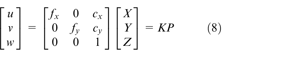
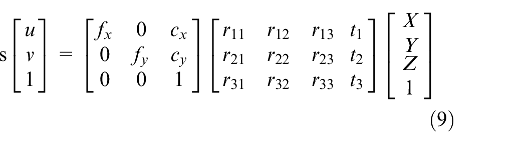
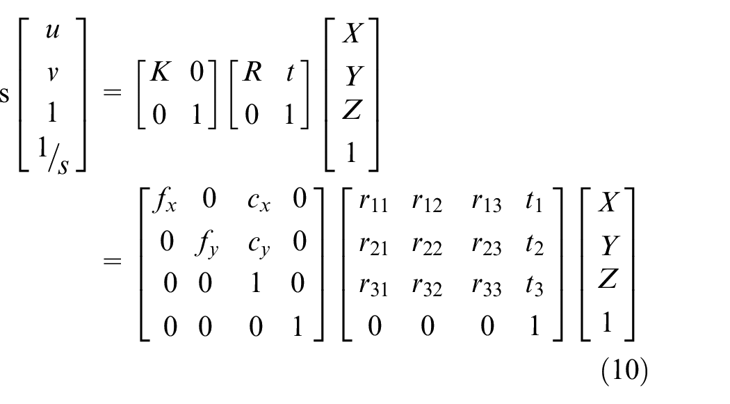
Where K is called intrinsic parameter matrix, because the parameters of this matrix are all related with the parameters of interior of the camera. By intrinsic parameter matrix, we can transform coordinates between camera coordinate system and image coordinate system, as shown in equation (9).
Where
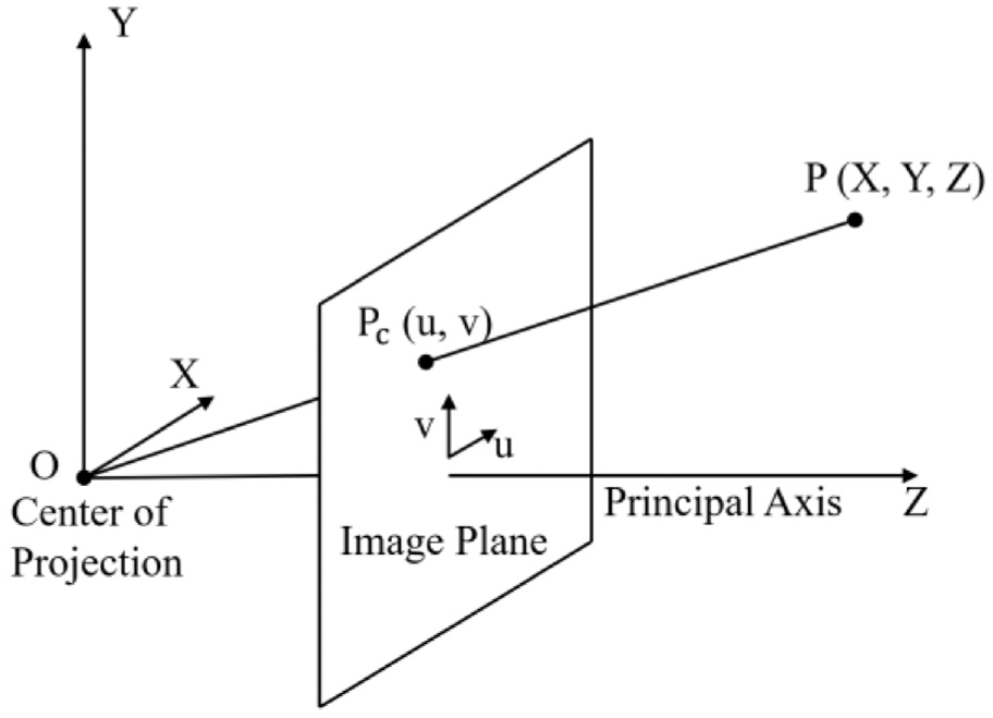
Camera with center of projection O and Z-axis parallel to principal axis. 21
The point cloud comprises a lot of points in 3D space and each point position has its set of Cartesian coordinates
We can verify the above equation with a simplest case that the origin on camera coordinate system and the origin on real coordinate system are aligned. It means that rotation matrix
According to equation (11), we can get
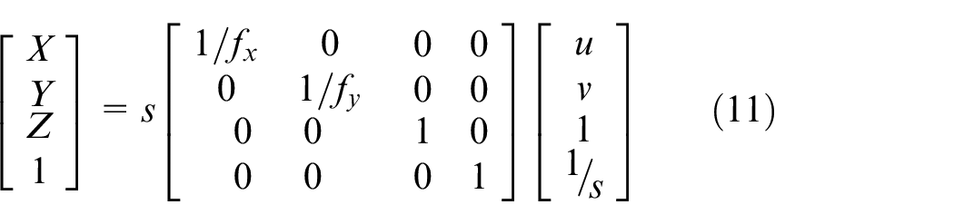
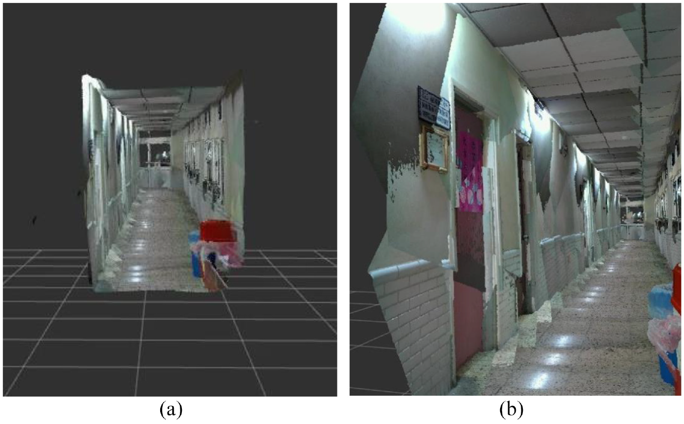
In the beginning, the 3D point cloud map is added RGB color, as shown in Figure 13. But there are some problems: since LiDAR camera inevitably has some noise and has problems when irradiate transparent object such as glass, some messy point clouds can be saw in Figure 13; and plenty of point clouds data leads to long delay time and high usage rate of GPU, as shown in Figure 14. In order to solve these problems, two filters are used. One is the average filter and the other is the voxel grid filter.
Point clouds with RGB color: (a) in front of the corridor and (b) looking down from above.
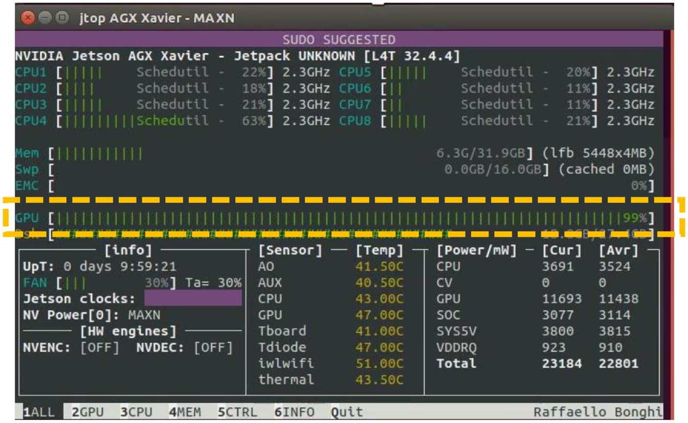
High usage rate of GPU.
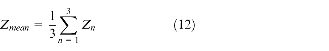
The average filter is used to eliminate messy point clouds, as shown in equations (12) and (13). To make it simple, this filter collects data three times at same position and every point is calculated to obtain its depth of mean. The point is deleted as long as it meets one of these conditions: the difference between its depth and its depth of mean is more than 0.3 m; its value of depth is more than 2 m; and its value of depth is 0. After using this filter, the result is shown in Figure 15. Obviously, messy point clouds are eliminated regardless of corridor or outside.
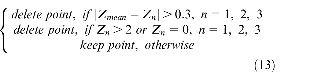
Point clouds with the average filter: (a) in front of the corridor and (b) in the corridor.
Where
To solve too much quantity of all point clouds data, it is necessary to reduce the amount of point clouds and retain the original shape characteristics. The voxel grid filter is used and RGB color is removed from map. The voxel is contraction of volume pixel, it is the minimum unit of three-dimensional space. The voxel grid filter is a voxel grid established at the three-dimensional space in the point cloud. For each voxel in the grid, all points are replaced by their average of centroid. Finally, constitute a filtering point cloud. Figure 16 shows the example of a voxel grid filter. 23 Figure 16(a) is original data points. The white dots are the data points, black dots are the centroids of each voxel. Figure 16(b) shows a big voxel size, where all data points are in the same voxel. Figure 16(c) is a smaller voxel size, with four centroids. The leaf size in here is 10 cm. Figure 17 shows the result used voxel grid filter.
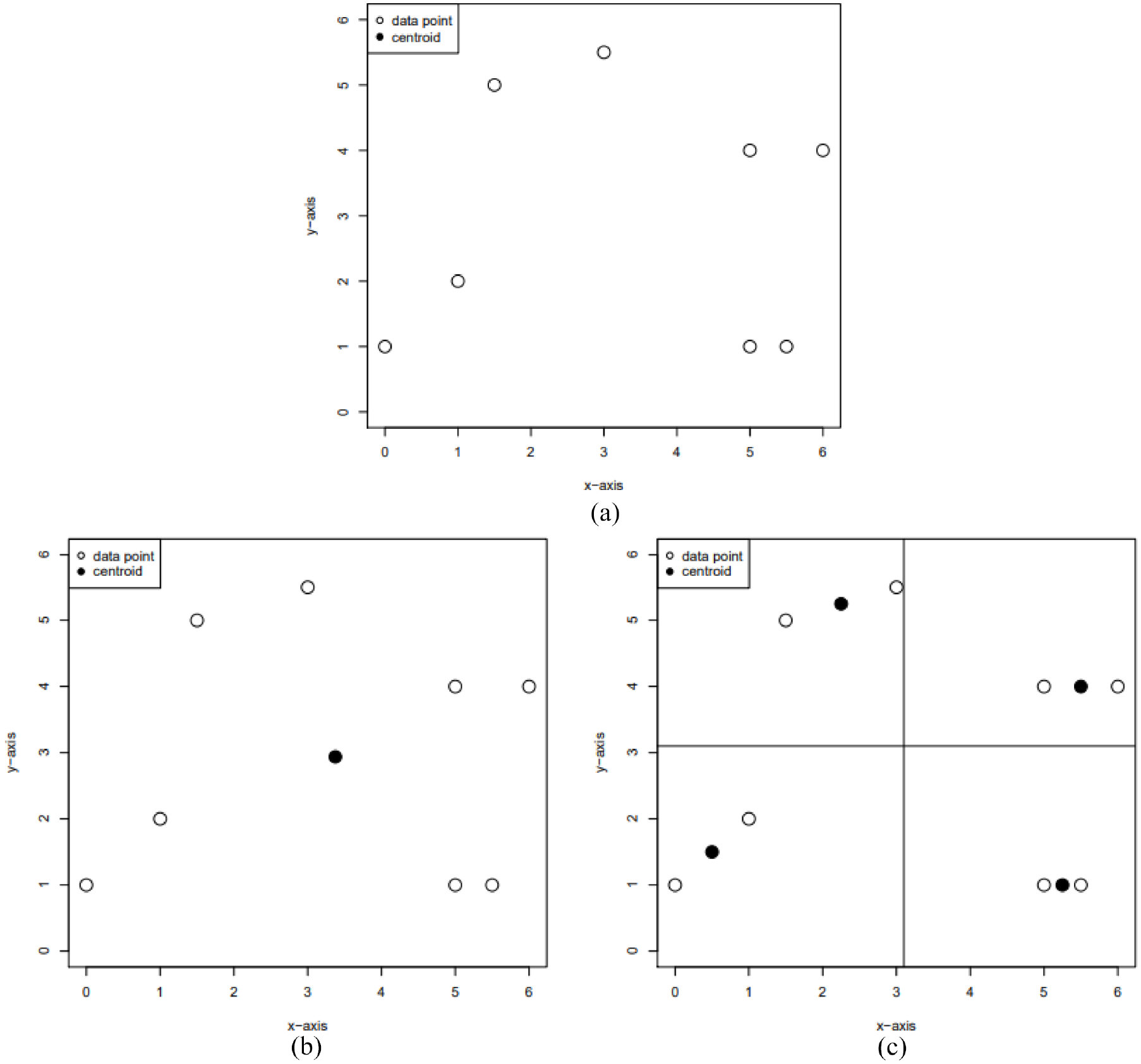
Example of voxel grid filter: (a) original data points, (b) big voxel size, and (c) small voxel size.
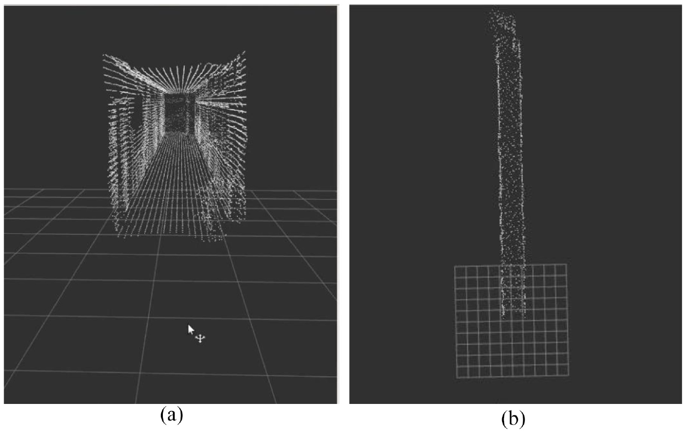
Point clouds used voxel grid filter: (a) In front of the corridor, (b) top view of corridor.
After utilize two filters, the size of map of corridor decreases to 368 kB from 2 GB as shown in Figure 18; the number of point clouds decreases to 11,698 from 30,412,801 as shown in Figure 19; time of publishing map data decreases to 0.1 s from 110 s as shown in Figure 20; and the usage rate of GPU becomes normal.
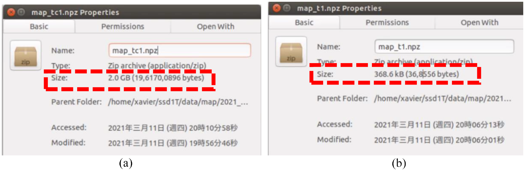
Difference of size: (a) size of not using filters and (b) size of using filters.

Difference of number of point clouds: (a) points of not using filters and (b) points of using filters.
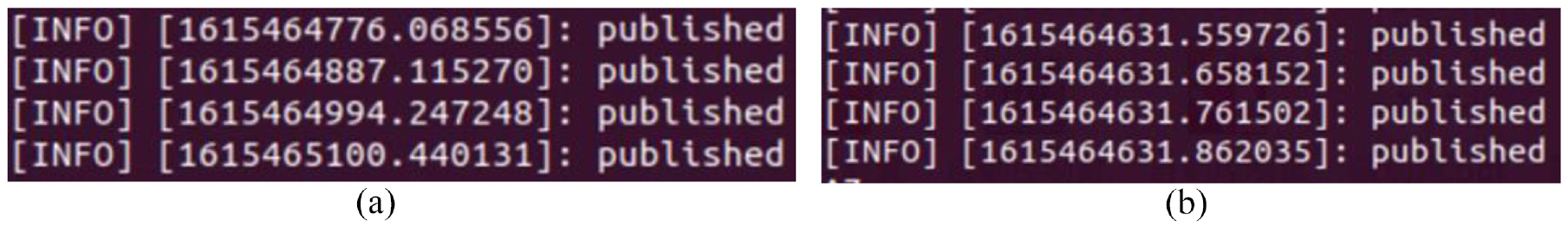
Difference of time of publishing map data: (a) time of publishing of not using filters and (b) time of publishing of using filters.
Object detection
In order to let the omnidirectional WMR know where it will go or where it is, we utilize that the image recognition algorithm combines with 3D point cloud map. By identifying some object that we choose, the omnidirectional WMR can obtain the coordinate of the object and plan the path then execute predefined task. The algorithm of object detection we selected is the YOLOv4. 20 The object detection algorithm with Convolutional Neural Networks (CNN) can be roughly divided into two genres; one is the two-stage represented by Region-CNN (R-CNN), 24 and the other is one-stage represented by YOLO. The principle of R-CNN utilizes Selective Search to extract about 2000 region proposals, and then each region proposal is predicted through a CNN channel. The theory of YOLO uses the whole image as input, and then output of prediction is performed by the CNN channel. Therefore, YOLO has faster speed and lower accuracy than R-CNN. In our experiment, the omnidirectional WMR needs the real-time reaction, so we choose YOLO for object detection. The YOLOv4 we used is improved on the basis of the YOLOv3. 25 Figure 21 shows the structure of YOLOv4, and its number of network layer is 161, more than YOLOv3. It adds a new module CBM which is the Convolution + Batch Normalization + Mish. YOLOv4 used new data augmentation, refers to CutMix, 26 called Mosaic. The theory of Mosaic is that randomly select four images in the input picture to randomly magnify or shrink, randomly cut, randomly distort, and then stitch them into one picture, the purpose is to enrich the sample data set. In the backbone, Cross Stage Partial Network (CSPNet) 27 substitutes for ResNet which is used in YOLOv3. The CSPNet replaces Add with Concat to extract the richer feature, and utilizes transition layer (1 × 1 convolution + 2 × 2 pooling) to extract features that reduce computing quantity and improve speed. In the neck, YOLOv4 used FPN and Path Aggregation Network (PANet) 28 to enrich feature of each level. In the head, CIoU loss substitutes for IoU loss, it can improve the problem that unable to know the distance of two and unable to distinguish the situation of overlap of two. The formula of CIoU loss is shown in equation (14).
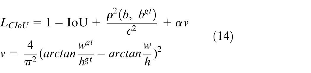
Where
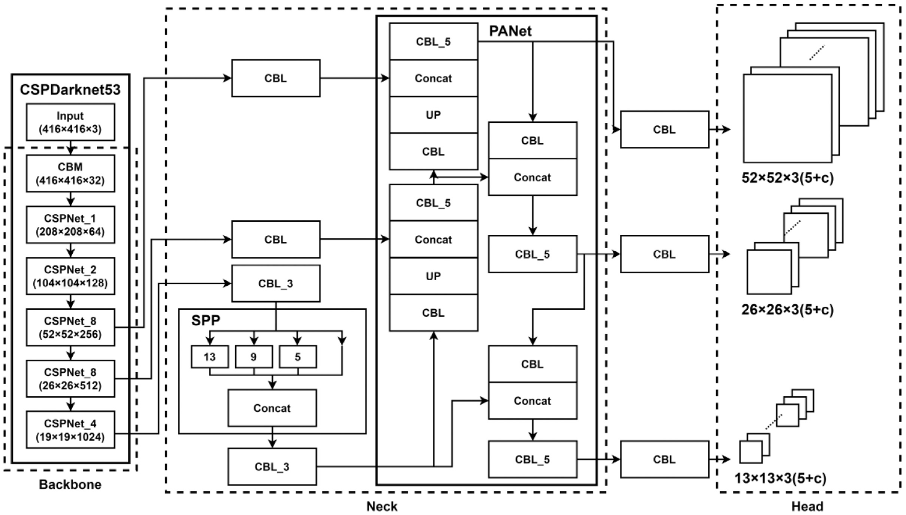
Structure of YOLOv4.
In the mapping, there are several points that the omnidirectional WMR collects the RGB image and depth map. The distance between two points is about 1 m. At every point, the neck of omnidirectional WMR rotates nine angles for collecting data completely. The directions of LiDAR camera face on upper left, upper middle, upper right, middle left, middle, middle right, lower left, lower middle, and lower right. The outwards and RGB images with YOLOv4 object detection are shown in Figure 22. After collecting data on one of points, the omnidirectional WMR moves forward 1 m to next point, stops, and performs the data acquisition.
LiDAR camera and RGB image face on each direction.
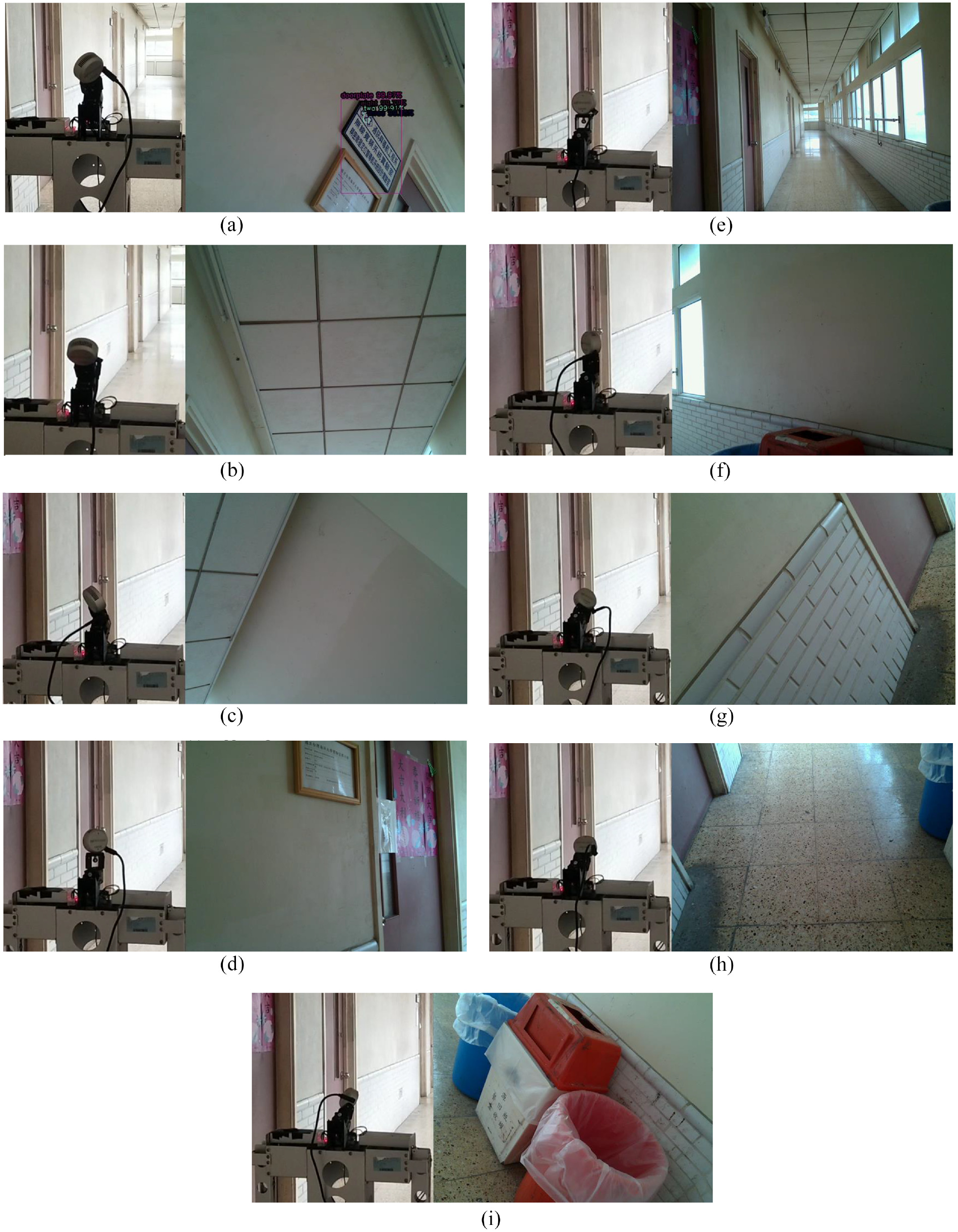
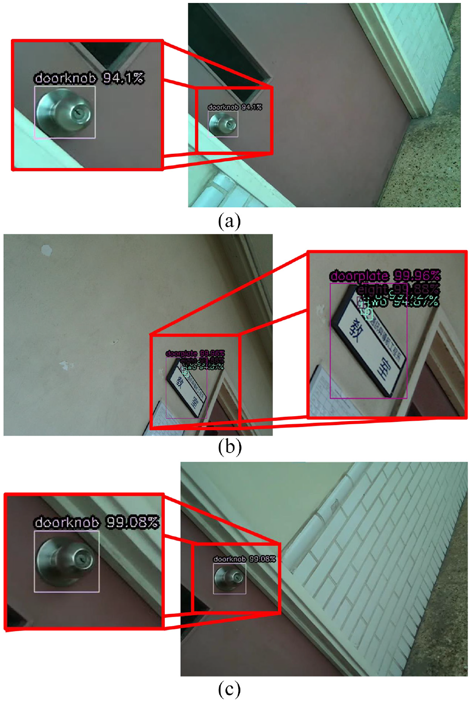
If the object is detected when omnidirectional WMR collects data, the bounding box is drawn on RGB image. Using the center of bounding box of object detection, the object coordinate in real world coordinate system can be obtained by point cloud. If the class of detected object is doorknob, the point cloud coordinate of center of bounding box and its class are directly recorded. When numbers and doorplate are identified and numbers are located in doorplate, detected numbers and their sequence are checked by a room number table. Only the numbers and sequence conform to the room number table, those numbers will be recorded. Collect and save those data of classes and coordinate in a file. Figure 23 shows the information of objects in file, class 0 represents doorknob. Figure 24 shows some images with recognized objects.
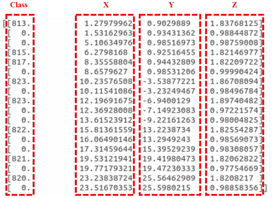
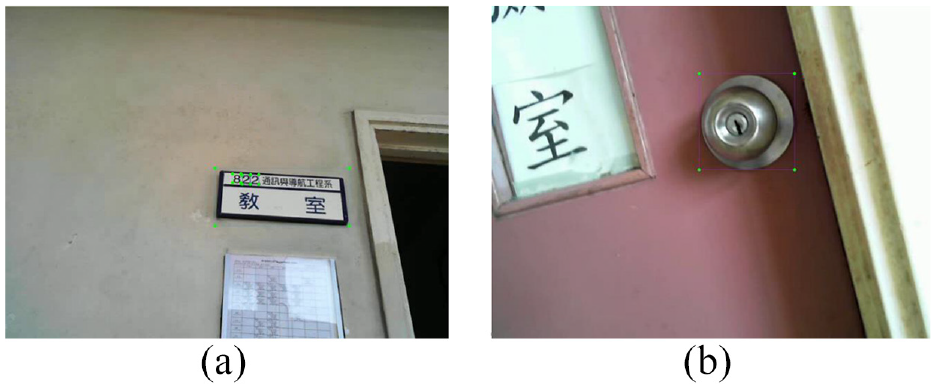
Information of objects in file: (a) doorknob on red door, (b) doorknob on blue door, (c) 823 on doorplate, (d) 822 on doorplate, and (e) 815 on doorplate.
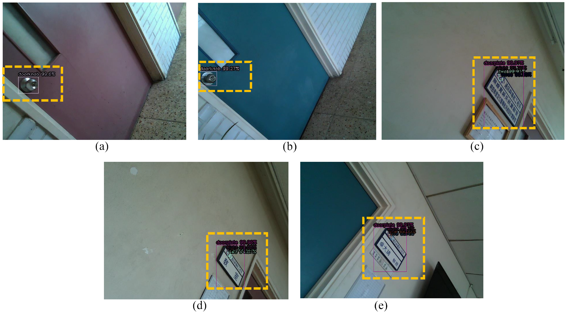
Images with recognized objects.
After all 3D point cloud map and information of object are obtained and saved, they are combined and displayed on the RViz. Figure 25 shows the flowchart of combining map with object location. Figure 26 shows the corridor in the original 3D point cloud map. The doorknobs and room number 822 with doorplate are recognized nearby this place, as shown in Figure 27. The coordinate data of objects from the file is converted into form of Marker which can be shown words at specific position on the RViz. By publishing topics that 3D point cloud map and these Marker, the RViz subscribes these topics and shows the map and object location, as shown in Figure 28. The green word is doorknob and the yellow number is room number.
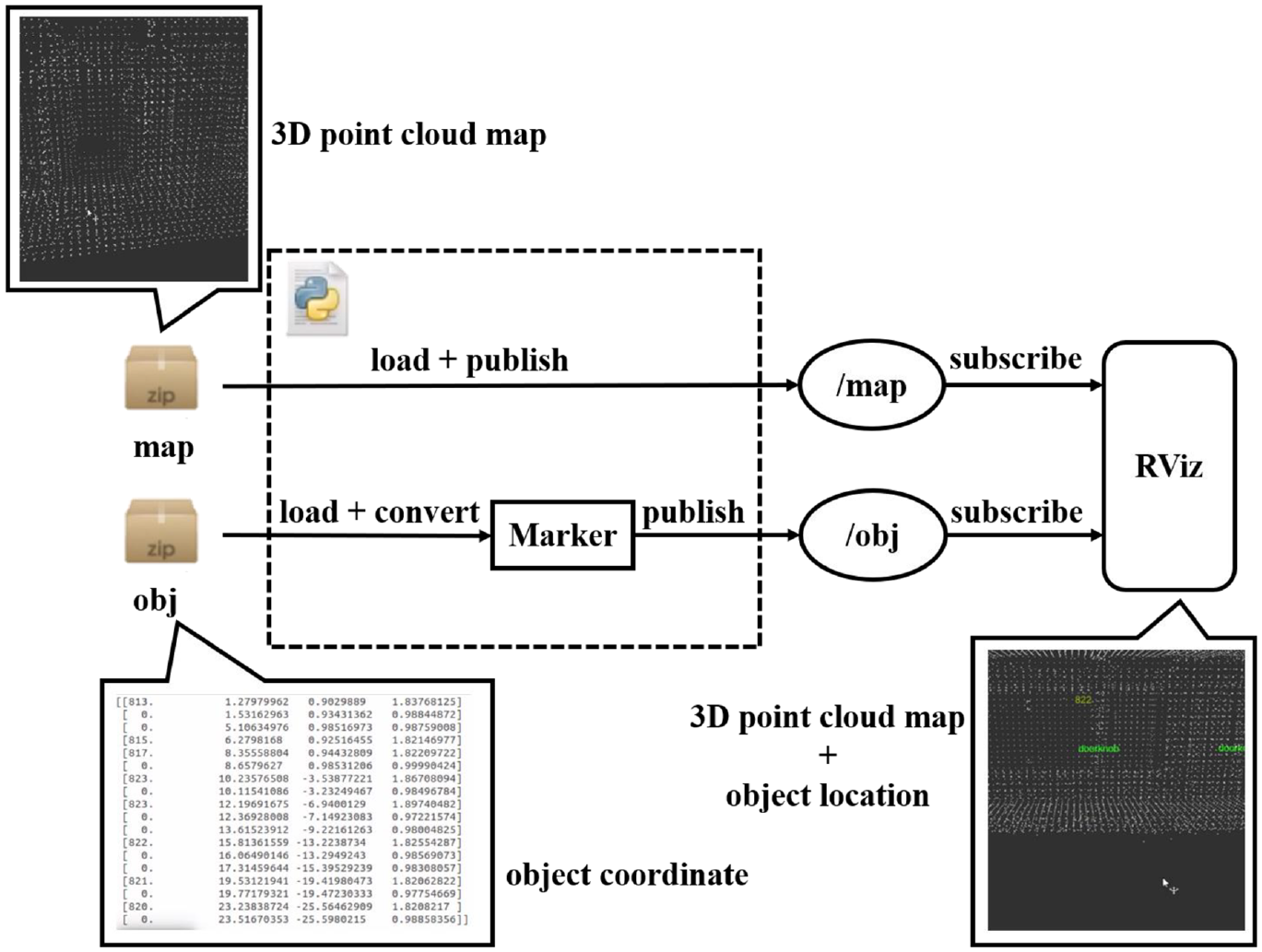
Flowchart of combining map with object location: (a)top view and (b) side view.
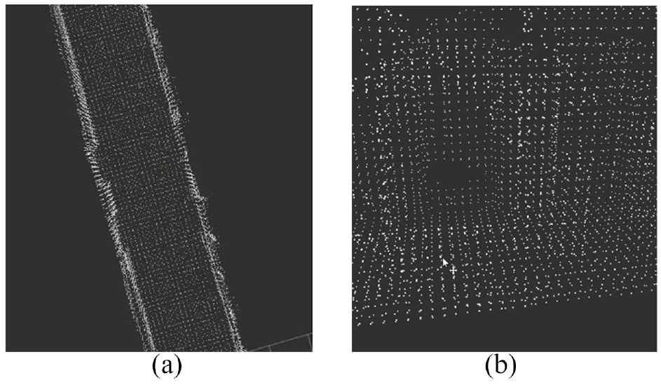
Corridor in original 3D point cloud map: (a) doorknob 1, (b) room number 822 on doorplate, and (c) doorknob 2.
Object detection: (a) top view and (b) side view.
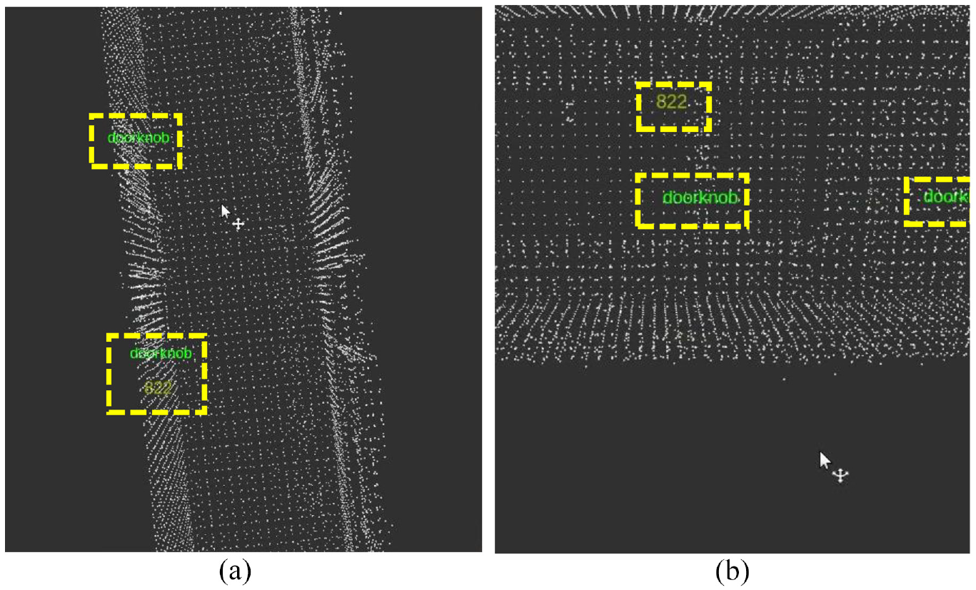
3D point cloud map with object location.
Experiment results
In the part of recognizing the particular object in our experimental environment, we utilize the images of doorknob, doorplate, and room numbers. There are 4500 images in our dataset, including 2800 images of doorplate with numbers, 1100 images of doorknob, and 600 images of negative sample. We use these to be our training data and validation data. Figure 29 shows some portion of dataset.
The dataset (a) doorplate with door number and (b) doorknob.
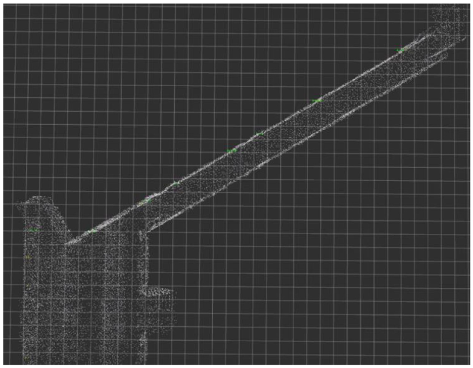
In the part of mapping, we set some points of pathway for omnidirectional WMR, then the robot goes through these points and collects information, as shown in Figures 30 and 31. Point cloud maps and its actual scenes of the experimental environment are shown in Figure 32. After mapping, we use RViz to display the 3D point cloud map, as shown in Figures 33–35.
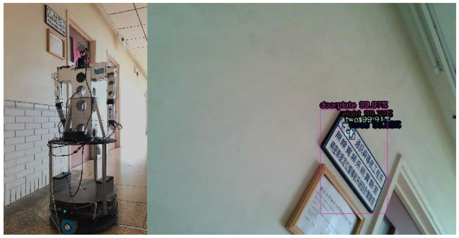
Omnidirectional WMR detect the doorplate of room 823 in mapping.
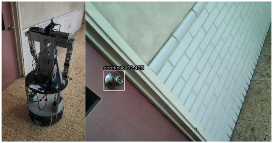
Omnidirectional WMR detect the doorknob in mapping: (a) Scene 1, (b) Scene 2, and (c) Scene 3.
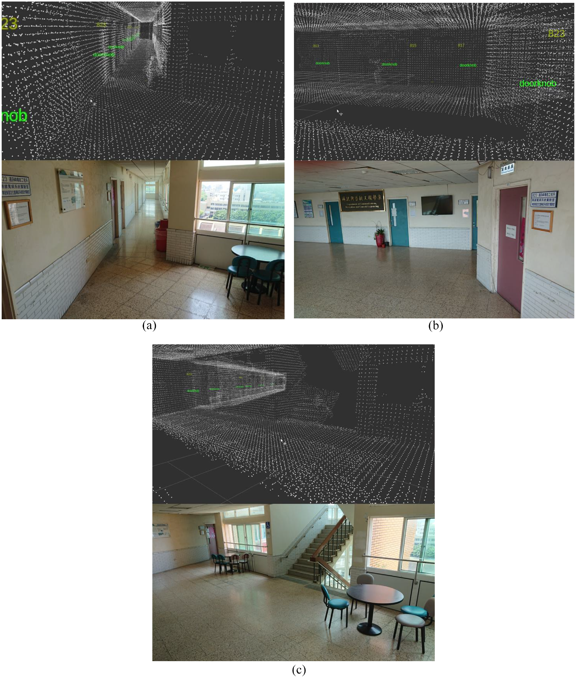
Point cloud map and its actual scene.
Top view of 3D point cloud map.
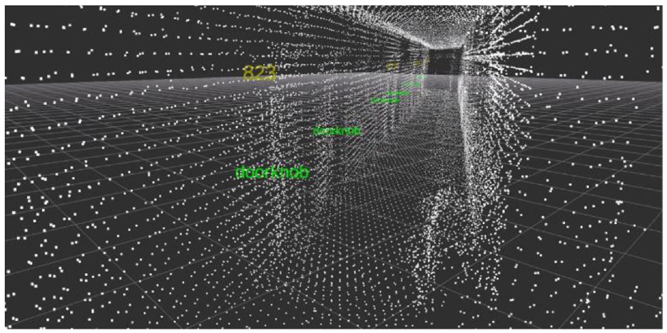
The corridor in 3D point cloud map.
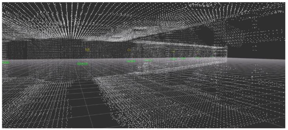
The hall in 3D point cloud map.
In the part of navigation task, we plan the robot moves to room 822 from elevator door, the path in RViz is shown Figure 36. First, robot rotates its head to first point and moves forward, as show in Figure 37. If robot detects the doorplate, it will go close and check the door number, as shown in Figure 38. After checking the door number is 823, the robot rotates to next point and goes ahead. Finally, it detects the doorplate with room 822 and stops in front of the destination, as shown in Figure 39.
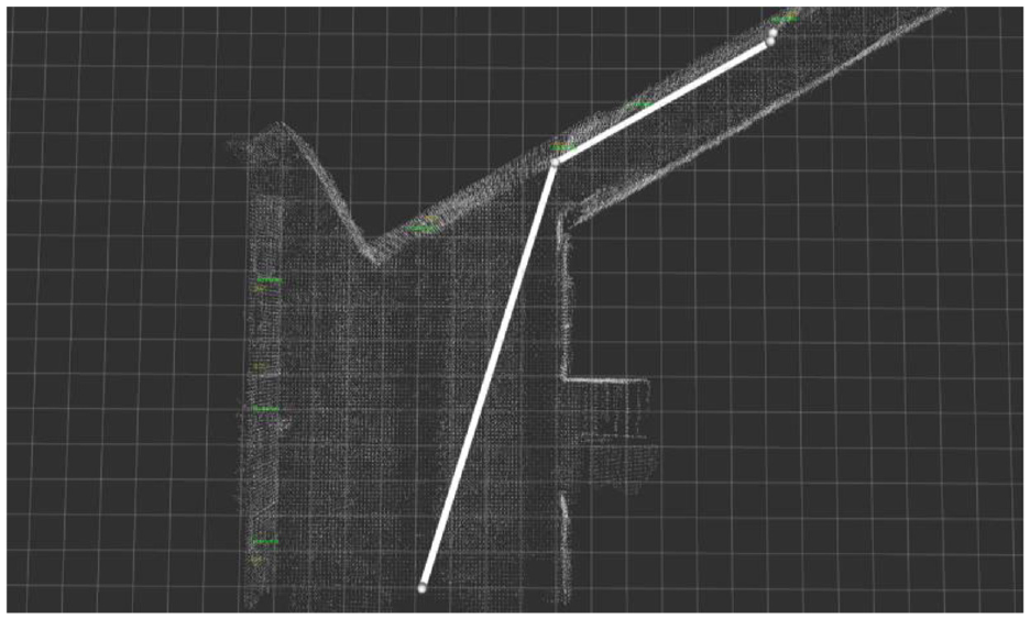
The path in RViz.
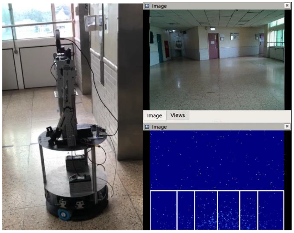
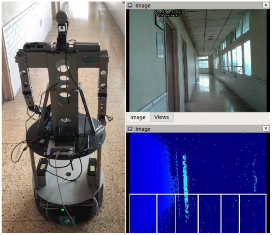
Initial position and the view from the omnidirectional WMR.
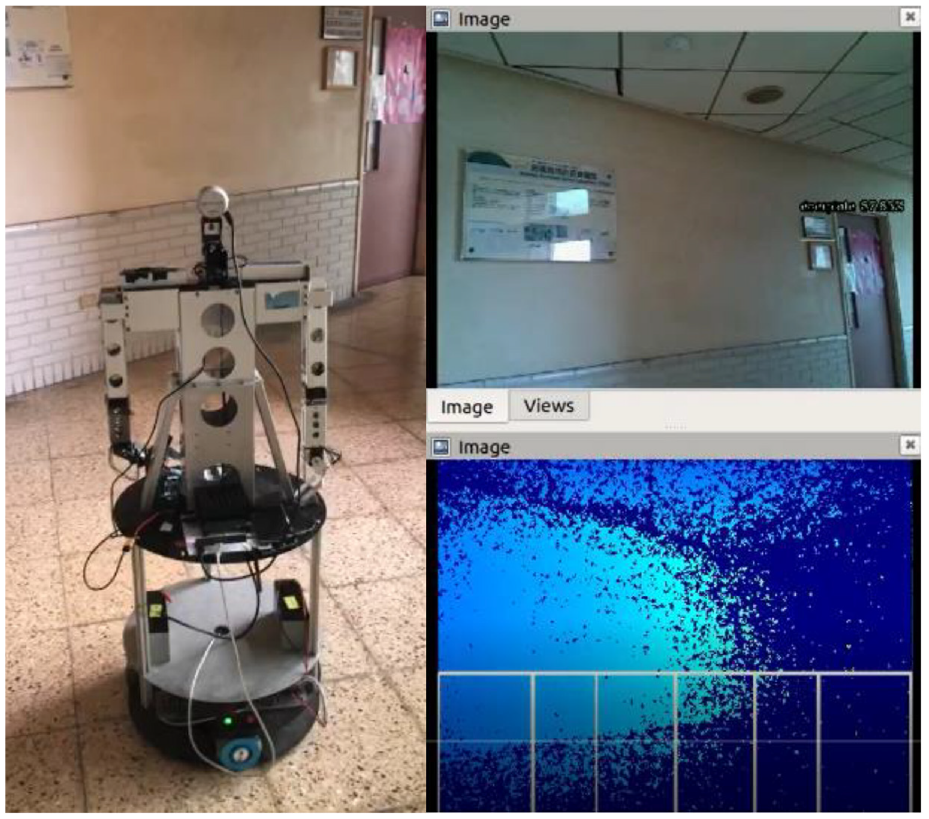
Omnidirectional WMR detects the doorplate.
Omnidirectional WMR detects the doorplate with room 822 and stops.
Conclusion
In this study, we integrate the methods of 3D point cloud map and image identification to mobile robot navigation. Compare to previous studies the main issue of this research is that we only use one camera to detect surrounding environment, and the wheels of the robot are controlled via camera image. Although there are many researches using visual control in indoor navigation, this study applies both RGB image and depth image to make the robot follow waypoints and avoid obstacles. By using Python and ROS, we can get the information of LiDAR camera which provides patrol route and feature positions for indoor navigation usage. Based on the image information, the robot can be controlled to track the planned nodes of the predefined path and perform desired task. In image processing, the YOLOv4 is utilized to recognize the particular object, and the robot will know where it is by 3D point cloud map and depth information. From the experimental results, we can see the proposed scheme is simple, but it actually can achieve the indoor navigation. In the future, task of indoor service can be added to this system, such as open door, take elevator, deliver documents, etc.
Footnotes
Declaration of conflicting interests
The author(s) declared no potential conflicts of interest with respect to the research, authorship, and/or publication of this article.
Funding
The author(s) received no financial support for the research, authorship, and/or publication of this article.