
Abstract
According to the principle of system identification, the least squares algorithm and MATLAB system identification toolbox is used to identify the model of the test bench of the vibration mirror swing scan system with the step signal and the vibration mirror swing-sweep angular displacement as the input and output quantities. Taking the identification model as the object, a sliding mode variable structures composite controller of fuzzy switching gain adjustment is designed. In the controller, according to the actual conditions achieved by the sliding mode, the switching gain is effectively estimated, so as to eliminate the interference of uncertain factors and high-frequency vibration. At the same time, the sliding mode function and sliding mode controller of the system needs to be designed. The switching hyperplane of the system is designed using the fuzzy switching method and the desired dynamic characteristics of the system, to ensure the smooth transition of the system state from outside the hyperplane to the convergence of the switching hyperplane. The simulation results show that: the new composite control method eliminates the shortcomings of PD series control, improves the response speed and tracking accuracy of the vibration mirror swing scan system, and improves the overall performance of the system. And it has a strong ability to inhibit the adverse effects caused by changes in the parameters of the controlled object.
Keywords
Instruction
Vibration mirror is widely used in laser projection, machining, medical testing and image processing. It is an optical sweeping instrument that requires high response and high precision performance.1,2 Taking advantage of the high energy density of the ultraviolet laser light source,3,4 and the vibration mirror swing sweep system in the high-speed swing sweep process, the laser point light source can be transformed into a swing sweep energy surface, 5 which can produce fast, efficient, It has good effect of large-scale and high-efficiency sterilization and bacteriostasis. Therefore, it is widely used in the elimination of viruses and bacteria in cold chain, express delivery, logistics, medical treatment, epidemic prevention and daily items, etc., especially in the context of the new crown pneumonia epidemic raging around the world, it has more broad application prospects. 6
Due to the small damping ratio of the vibration mirror swing scan system, small loads inertia, and many uncertain factors, it is difficult to establish an accurate mathematical model. And in use of the system is required to have the characteristics of fast response, high precision, better stability and other harsh working conditions. So it is difficult to achieve its control requirements using conventional control algorithms. At present, domestic and foreign scholars have done a lot of research to improve the dynamic performance of the vibration mirror under high frequency working conditions. Zhong et al. propose an integrated control solution to realize the high bandwidth and high precision tracking of the vibration mirror. The internal digital electric charge control loop eliminates the hysteresis, and the external displacement loop eliminates the system resonance by means of zero-pole cancellation and uses the feedforward compensation method to eliminate the system phase lag. Finally, the feasibility of the method is verified by experiments. 7 Vibration mirrors require high speed and dynamic accuracy in high-end biomedical applications. Mnerie et al. propose a predictive control structure of driving a dual-axis dual-galvo scanner to achieve higher accuracy and higher working speed. Experiments are carried out for different types of input signals, and the results show that the control effect of the predictive control structure is better than that of the traditional proportional-integral-derivative controller (PID). 8 Zaeh and Pieczona used adaptive inverse control to improve the dynamic performance of the vibration mirror, compensated the dynamic model by considering the working characteristics of the vibration mirror, and verified the feasibility of the method of experiments, which is comparable to the traditional vibration mirror scanning Compared with the system, the optical error is reduced by about 95%. 9 When the vibration mirror works at high speed, it will generate a high temperature, which will cause thermal demagnetization, and cause the torque generated by the vibration mirror to decrease form the increase in temperature. Based on the above problems, Matsuka et al. developed a thermal demagnetization compensation method, which estimates the temperature of the magnet based on the detected current and compensates the torque. 10 Chen and Luo propose a high-speed vibration mirror control system based on the ARM cortex M7 core in order to solve the problems of high power consumption, low precision and complex circuits in the current vibration mirror system. The control system can effectively reduce the attenuation during the transmission of the control signal, and propose an effective optimal compensation for the inherent geometric distortion of the laser. 11 In order to improve the tracking performance of the vibration mirror laser tracking system, Wang et al. designed a composite control strategy based on feedforward and feedback. The controller adopts the additive output decomposition to suppress the disturbance caused by the system uncertainty, and improves the tracking performance of the vibration mirror system through the zero-phase error tracking controller. Finally, the residual error is compensated by the differential evolution driven PID without overshoot. The simulation results show that the combined controller can effectively reduce the influence of system uncertainty. 12 In view of the fact that the digital laser vibration mirror system is easily affected by uncertain factors such as parameter changes and external disturbances, Wangyunlong adopts an adaptive discrete synovial variable structure control strategy based on the approach rate. The simulation results show that the controller It has good performance and can meet the practical application. 13 In order to reduce the noise of the angle sensor and achieve higher quality motion, Ito et al. successfully reduced the residual tracking error by 41% by noise reduction when the swing angle of vibration mirror scanning was 10 at 20 Hz through the inverse iterative control (IIC) algorithm. 14 To improve the compatibility, portability and network management of the system, Xiaojun et al. designed an Ethernet laser vibration mirror controller based on FPGA. The test results show that the controller can accurately control the rotation angle of the vibration mirror, and it solves the problem of poor compatibility of traditional control boards based on PCI interface for data transmission. 15
To sum up, scholars at home and abroad mainly focus on eliminating hysteresis, improving system bandwidth and system dynamic accuracy, and compensating the errors caused by viscous friction, component accuracy, external interference and thermal demagnetization during vibration mirror operation through different control strategies. In the process of designing the control strategy of the system, the accuracy of the mathematical model of the vibration mirror system is very important to the design of the control strategy of the system, but the precision of the components of the vibration mirror and the viscous friction will have a great influence on the accuracy of the mathematical model of the system. And in the actual working process, there will be uncertain factors, such as external interference, system noise, thermal demagnetization and other phenomena, and the dynamic error will change to a large extent. Therefore, it is of great significance to construct an accurate mathematical model of the vibration mirror system and to design a controller that can compensate for errors caused by uncertain external disturbances.
The sliding mode control strategy designs the switching hyperplane of the system according to the desired dynamic characteristics of the system, and then uses the sliding mode controller to make the system state converge from on the hyperplane to the switching hyperplane. After reaching the switching hyperplane, the control action will ensure that the system reaches the origin of the system along the switching hyperplane. The control effect is obvious, so the control strategy has been widely used.16–19 The advantage of fuzzy control technology is that it does not need to know complex and precise mathematical models, and only needs to realize control according to experience and rules. 20 Aiming at the problems of the above-mentioned vibration mirror swing scan system, a new sliding mode controller of fuzzy switching gain adjustment is designed by combining the advantages of both the sliding mode control strategy and the fuzzy control technology. At present, the measures taken to improve the performance of fuzzy control is as follows: For the quantization factor, a self-adjusting correction factor is introduced. This method embodies the automatic adjustment of the weight of the error to the control effect according to the size of the error, and solves the problem that the two cannot adapt to different controlled objects because they are in the same weighted degree. The self-adjusting factor fuzzy controller has fast response, small overshoot, and strong robustness to parameter changes.21–23 For the scale factor, the integral factor is introduced to solve the problem that the selection of the scale factor of the conventional fuzzy controller cannot meet the requirements of rapidity and steady-state accuracy at the same time. The rapid response from the system is ensured by sett the scale factor, and the higher steady-state accuracy of the system is ensured by selecting a smaller integral factor. 24 In terms of compound control, parallel fuzzy control and dual-mode fuzzy control combine the advantages of fuzzy control and other controls to improve the dynamic characteristics of the system.25,26 The above is only an improvement in the fuzzy control from various parts, and the optimal effect cannot be achieved.
The author of this paper proposes a sliding mode control strategy for fuzzy switching gain adjustment. The control principle is to effectively estimate the switching gain through fuzzy rules and according to the fuzzy rule interval corresponding to the actual conditions achieved by the sliding mode, so as to quickly eliminate uncertain external disturbances induced dynamic errors and eliminate vibration. When the frequency of the system input signal increases, the systems corrected by the series PD correction controller and the synovial variable structure controller has different degrees of phase lag and steady-state error. In contrast, the sliding mode control strategy of fuzzy switching gain adjustment is not only stable in the region near the operating point, but also in the region far away from the operating point (in the dynamic process of large deviation), it can quickly converge to the region near the operating point, and then Eliminate the oscillation and deviation near the working point to achieve the purpose of improving the rapidity and accuracy of the system. When the vibration mirror is subjected to uncertain external interference, the value of the synovial membrane existence condition
Model identification of the vibration mirror swing scan system
Principle of system model identification
System identification is a method of fitting and obtaining a more accurate system model based on the input data and output data onto the system and according to the optimal principle after the system motion is stable. 28 The basic principle is shown in Figure 1.
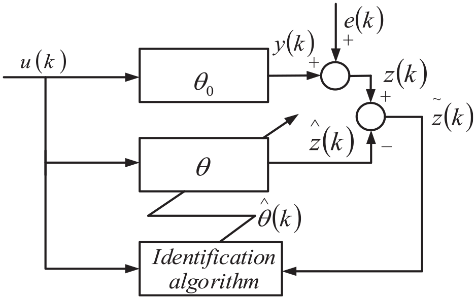
Schematic diagram of system identification.
In Figure 1,
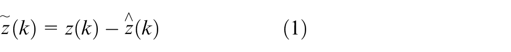
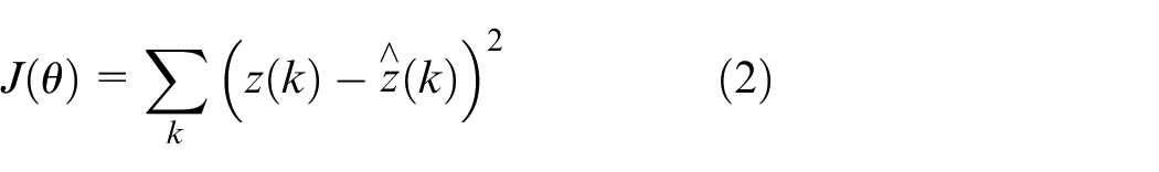
The residuals and estimation criteria of the identification system are shown in equations (1) and (2).
During the identification process, the system will input the residual error calculated by the system into the identification algorithm, output the estimated parameter value of
System identification criteria
It is known that the theoretical mathematical model of the vibration mirror swing scan system is a second-order system. After obtaining the input and output data onto the actual work of the experimental bench, the model of the system can be identified. Since the order for the system is known, and the least squares method can find the estimator that minimizes the sum of squares of the residuals from a class of models, and under the condition of white noise, the algorithm has unbiased, consistent and effective. Therefore, in this paper, the least squares method is used to identify the system. 29
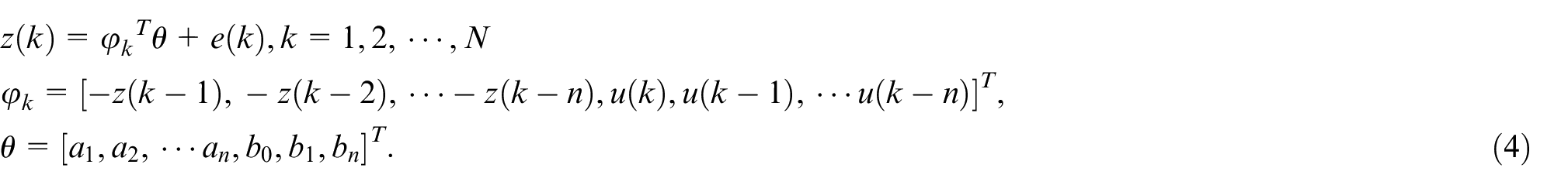
Set the system equation as shown in equation (3).
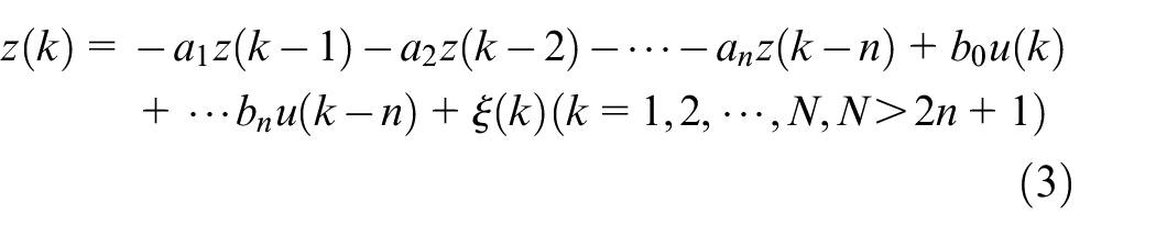
Where
Equation (3) can be simplified to the standard form of equation (4).
When
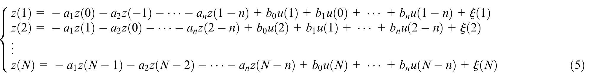
Then equation (5) can be simplified to the matrix form of equation (6).

Where
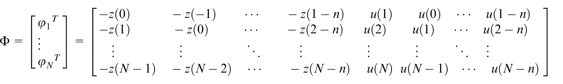
Then the output observation matrix and the measurement error matrix are shown in equations (7) and (8) respectively.


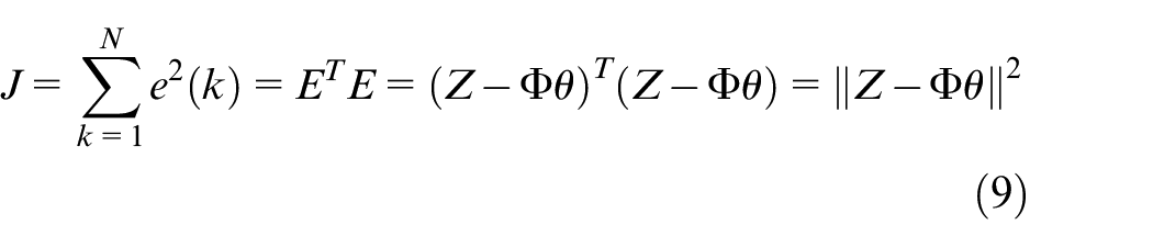
The estimation criterion of the least squares method is to minimize the sum of squares of the residuals of the system. Let the sum of squares of the residual error of the system be
System identification of the vibration mirror system
There are many factors that affect the dynamic performance of the vibration mirror system, for example, the viscous friction in the system has a great influence. Different friction coefficients will make the system show under-damped, critically damped and over-damped states. During the system identification of the vibration mirror system, when the input frequency of the system is 5 Hz, the voltage amplitude is 2 V and accompanied by a square wave signal of random white noise, the actual output signal of the vibration mirror motor is detected. Processing of acquired data onto MATLAB after data extraction. Figure 2 shows the comparison of input and output signals. By comparison, it can be seen that although the output lags behind the input signal, the overall fit are very high.
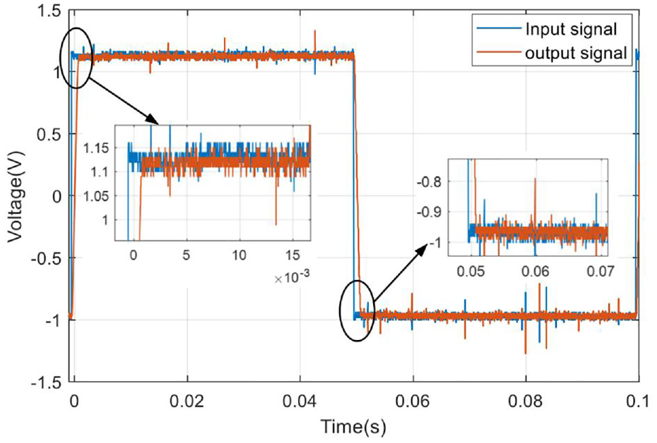
Input and output response curve of vibration mirror motor.
The identification model of the vibration mirror system is identified by using the least squares algorithm and the Matlab system identification toolbox through the state observation of the actual input and output of the vibration mirror motor. The transfer function of the system after identification is shown in equation (10).
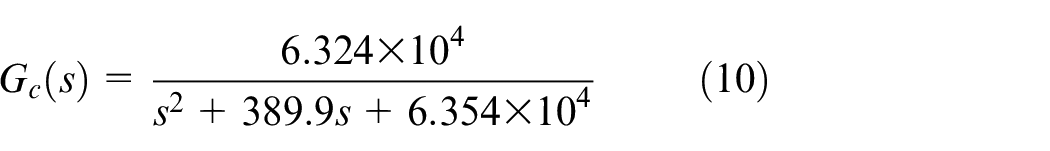
It can be seen from equation (10) that the damping ratio of the system after identification is
The closed-loop frequency curve of the identification system.
Error analysis of identification system
In the case of considering viscous friction damping, the difference between the theoretically derived mathematical model of the vibration mirrors system and the frequency domain characteristic curve of the system identification model is small. This also indirectly shows that the influence of viscous friction damping on the dynamic characteristics of the system cannot be ignored. The difference between the two models is mainly reflected on the difference in the cutoff frequency. The viscous friction effect of the actual system is related to many factors, and the environment, temperature, etc. will also have a certain impact on the dynamic performance of the system. Therefore, although the identification model of the system can be preliminarily determined from the frequency domain characteristic curve to be relatively accurate, its steady-state error value needs further analysis. The following is a steady-state error analysis of the unit step response and sinusoidal response of the system. The accuracy of the identification model is further verified by comparing the steady-state operating conditions of the system under different friction coefficients.
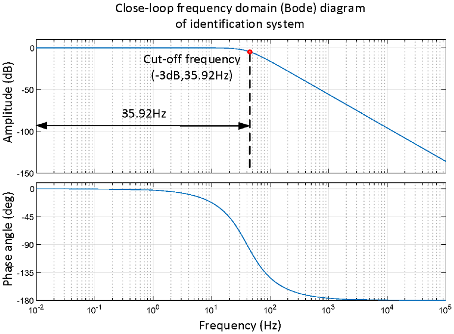
Figure 4 shows the unit steps response curves of the non-viscous friction system, the identification system and the system considering the viscous friction coefficient. It can be seen from the figure that the unit steps response oscillation of the non-viscous friction system is more obvious, and the system is not easy to stabilize. Its rise time is
Unit step response curves of different systems.
Figure 5 shows the sinusoidal response curves of the non-viscous friction system, the identification system and the system considering the viscous friction coefficient. When inputting a sinusoidal signal with a frequency of 5 Hz and an amplitude of 1°, the steady-state errors of the identification system and the system considering the viscous friction coefficient are 0.0079 and 0.0239, respectively, and the phase angle lags are 11.04° and 15.42°, respectively. It can be seen that the steady-state error difference between the identification system and the system considering friction coefficient is small under the condition of sinusoidal signal input, which shows the accuracy of the identification model.
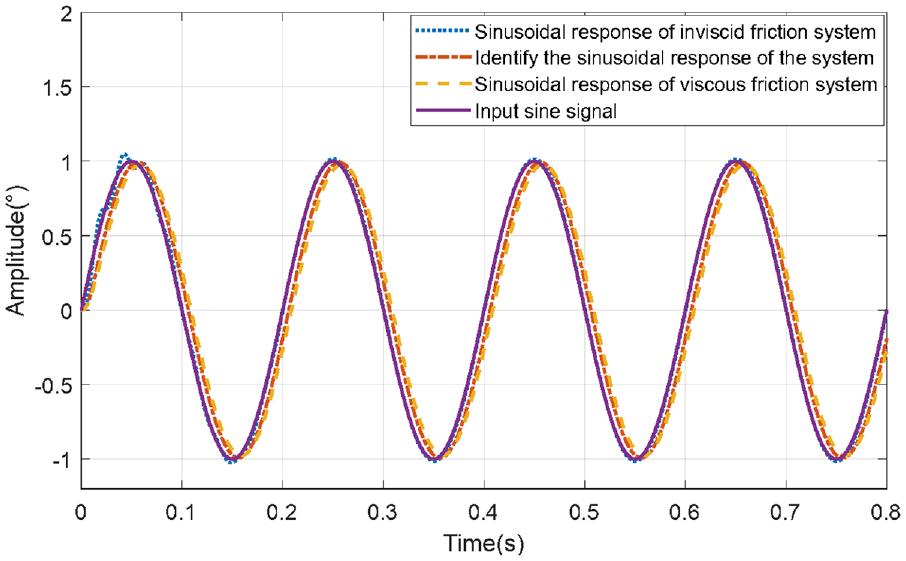
5 Hz sinusoidal response curves of different systems.
Figure 6 shows the sinusoidal response curves of the non-viscous friction system, the identification system and the system considering the viscous friction coefficient. When inputting a sinusoidal signal with a frequency of 20 Hz and an amplitude of 1°, the steady-state errors of the identification system and the system considering the viscous friction coefficient are 0.0756 and 0.2632, respectively, and the phase angle lags are 48.1° and 54.96°, respectively. It can be seen that the steady-state error of the identification system and the system considering the friction coefficient become significantly larger at higher frequencies, and there is an obvious lag in the phase angle. Therefore, it is necessary to correct the system.
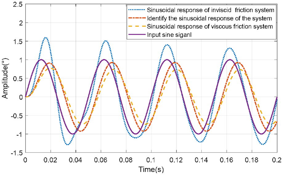
20 Hz sinusoidal response curves of different systems.
Design of fuzzy switching gain adjustment sliding mode controller
Establishment of the state space equation of the vibration mirror swing scan system
Take the state variable as
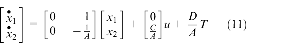
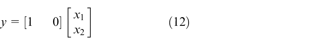
Where
In this paper, the rank criterion theorem, 30 that is, the state equation of a linear steady continuous system, is used to judge whether the state of the vibration mirror swing scan system is controllable or not.

Where A and B are
The necessary and sufficient conditions for the controllability of the linear steady-state system of equation (13) are shown in equation (14):

Where n is the dimension of the A matrix.
According to equation (14), the controllable discriminant matrix form of the vibration mirror system is:
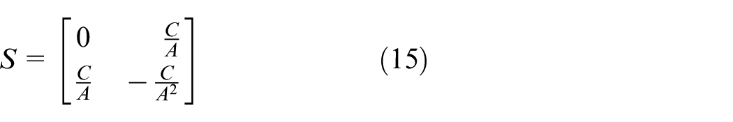
Then the rank of the controllable discriminant matrix S is rank S = 2, indicating that the matrix is completely controllable.
The necessary and sufficient conditions of the rank criterion for the observability of linearly constant systems 31 are:
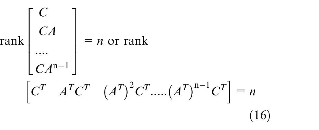
Then according to equation (16), the observation discriminant matrix form is:
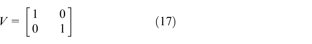
As can be seen from the observable discriminant matrix shown in equation (17), rank V = 2, which means that the state of the system is completely observable.
Design of sliding mode controller
Sliding mode variable structure control is to effectively estimate the switching gain according to the actual conditions achieved by the sliding mode, thereby eliminating interference and eliminating vibration.
32
Therefore, it is necessary to design the sliding mode function and sliding mode controller of the system. In general, the state space of the system is
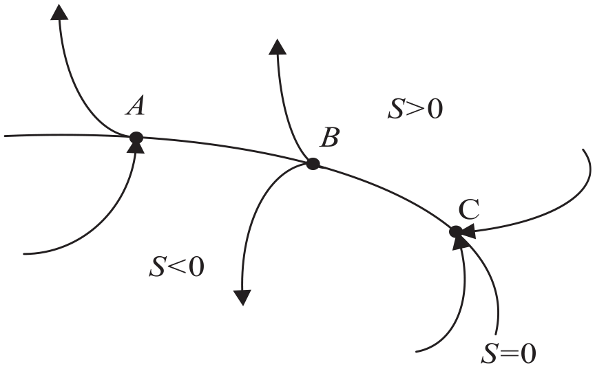
Schematic diagram of sliding mode switching surface.
During the movement of the system, the termination point has a special meaning. If all points in a certain area near the sliding surface are terminal points, the moving point will approach this area and will keep moving in this area. In this case, the area where all the sports stores are the termination points on the switching surface s = 0 is called “the sliding modal area.” When the system moves to the vicinity of the switching surface s = 0, the following relationship exists:
The design method of sliding surface s(x) is shown in equation (19)
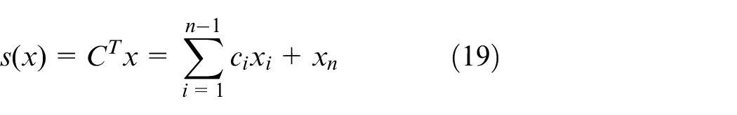
Where x is the state vector,
After further simplification according to the dynamic equation of the vibration mirror system, the differential equation of the system can be obtained as a second-order form, as shown in equation (20):

Since the difference between the actual angular displacement

Where

According to the above equation, it can be known that when
According to equation (22), the stability of the sliding mode control strategy is analyzed, and the Lyapunov function33,34 is taken as:
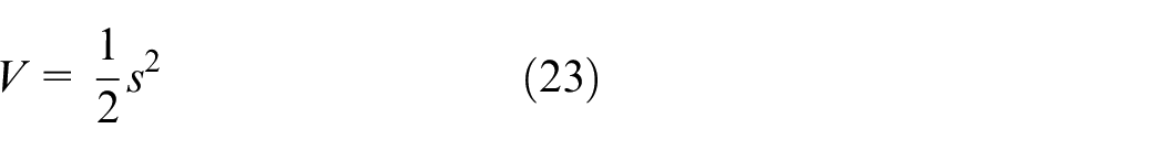
After derivation of the above equations, the following form can be obtained:
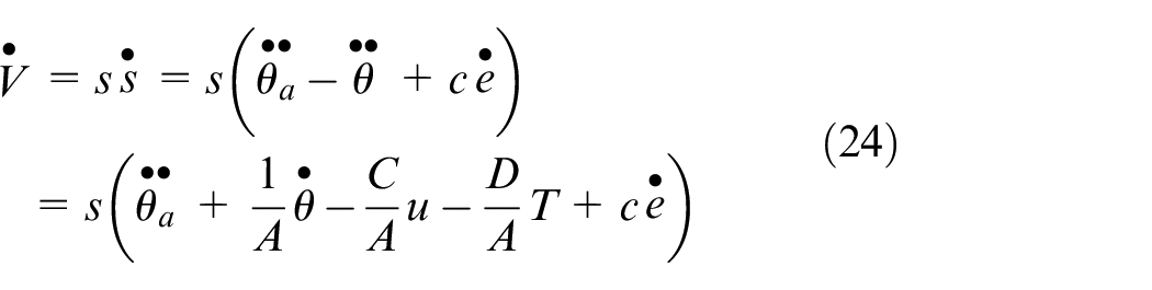
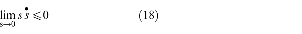
It is known that the condition of the vibration mirror swing sweeping system reaching the sliding mode surface and continuing on the sliding mode surface is
Where

According to equation (26), it can be seen that when s < 0,

Putting

According to formula (28), it can be known that
Among them,
In the formula,
Sliding mode controller with fuzzy switching gain adjustment
In this paper, the sliding mode control strategy of fuzzy switching gain adjustment is adopted. The essence of fuzzy control is based on human thinking and theoretical experience. The fuzzy rules are set for the system. In the actual control system, when the system model is uncertain, the automatic control of the system can be realized through fuzzy experience. Fuzzy control is mainly composed of four parts: fuzzy interface, knowledge base, fuzzy reasoning and defuzzification. 36 The schematic diagram is shown in Figure 8:
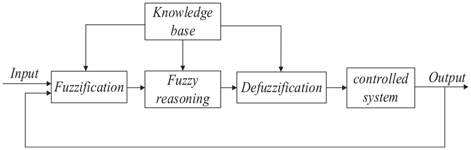
Schematic diagram of fuzzy controller.


Where
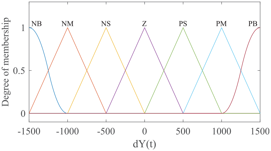
According to the above content, the input and output membership functions of fuzzy rules are established. The domain of input membership function
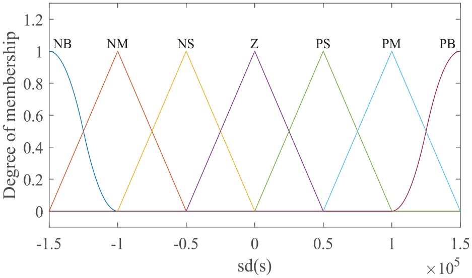
Input membership function.
Output membership function.
The corresponding relationship of fuzzy rules is established from the input and output function membership function curves of Figures 9 and 10, as shown in Table 1:
Fuzzy rules of input and output membership functions.
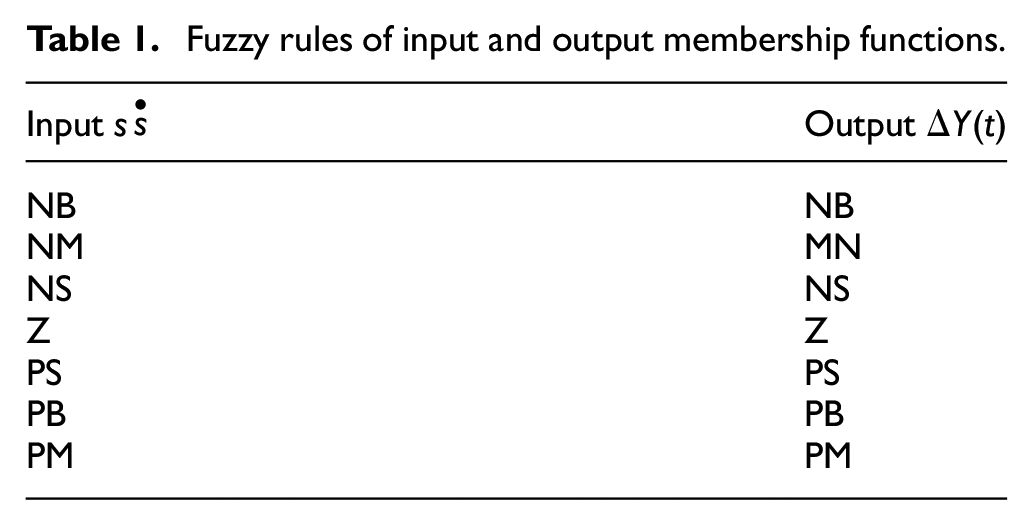
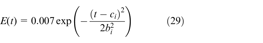
The fuzzy rules of input and output membership are shown in Table 1, and the gain
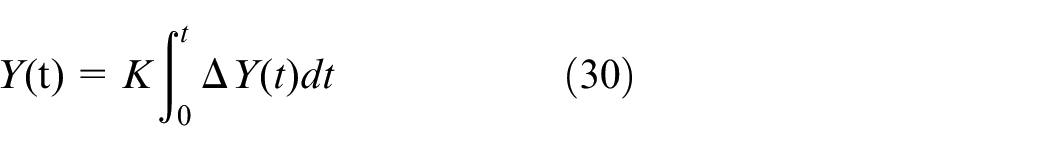
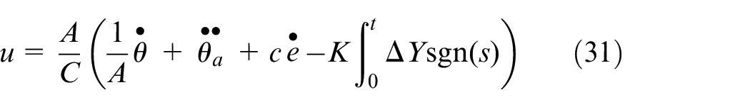
Where
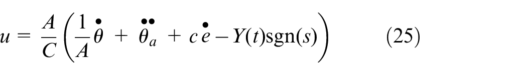
The synovial controller of fuzzy switching gain adjustment can be obtained as shown in equation (30).
The structure diagram of the sliding mode controller with fuzzy switching gain adjustment can be established by sliding mode control theory and fuzzy control rules, as shown in Figure 11:
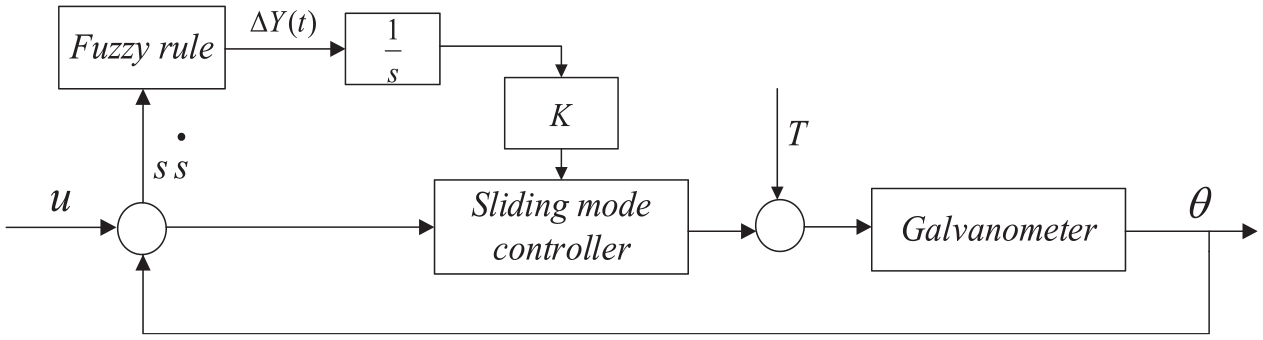
Schematic diagram of fuzzy switching gain adjustment sliding mode control.
Simulation analysis of fuzzy switching gain adjustment sliding mode controller
Based on the Matlab/Simulink function module, we simulate and analyze the dynamic performance of the vibration mirror swing scan system after the correction and control of the synovial controller with fuzzy switching gain adjustment. The simulation experiment model is shown in Figure 12. In this paper, sinusoidal position signals to different frequencies of 25, 60, and 110 Hz are used as input commands, and the corresponding position output responses are obtained. And compared with the output position curve of PD series correction and three closed-loop control system. In the simulation experiment, the noise form is normally distributed Gaussian white noise. Figure 13 shows the normal distribution curve of Gaussian white noise.
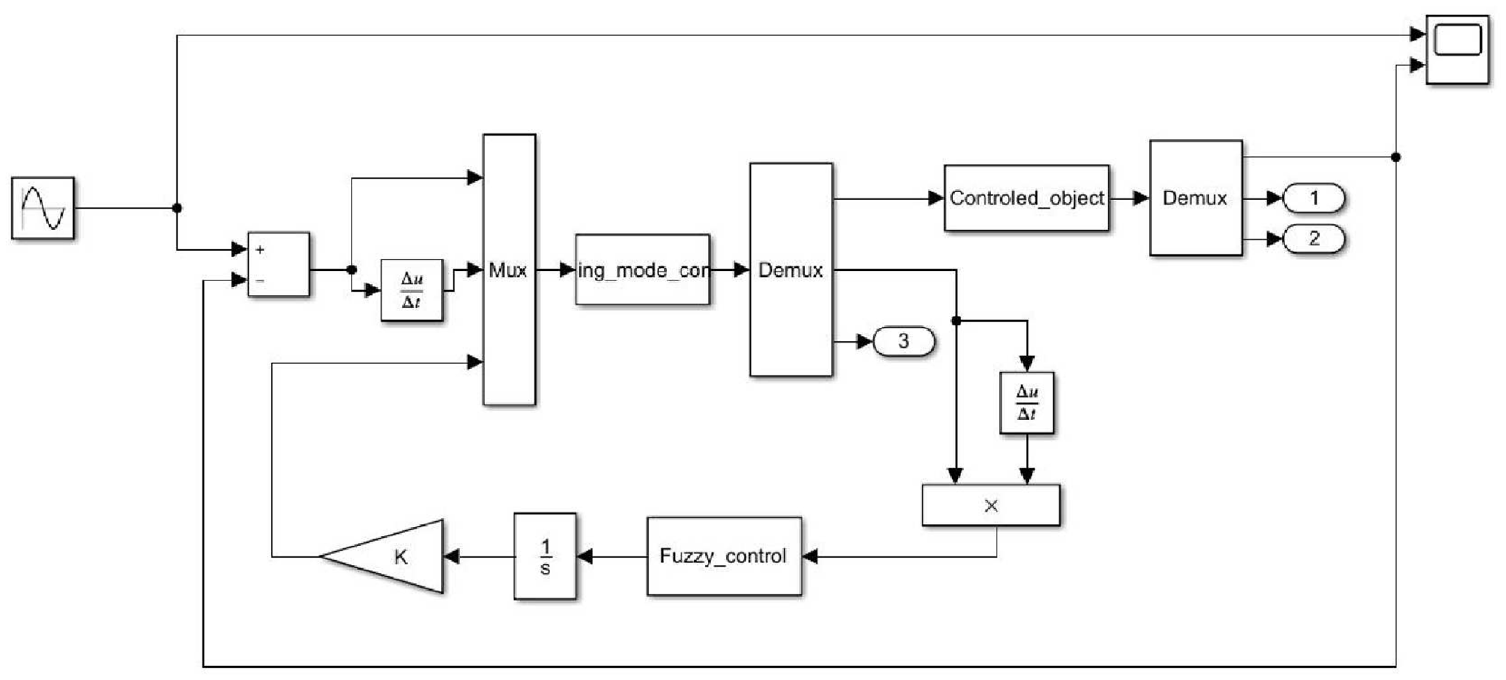
Simulink simulation model of fuzzy switching gain adjustment synovial controller.
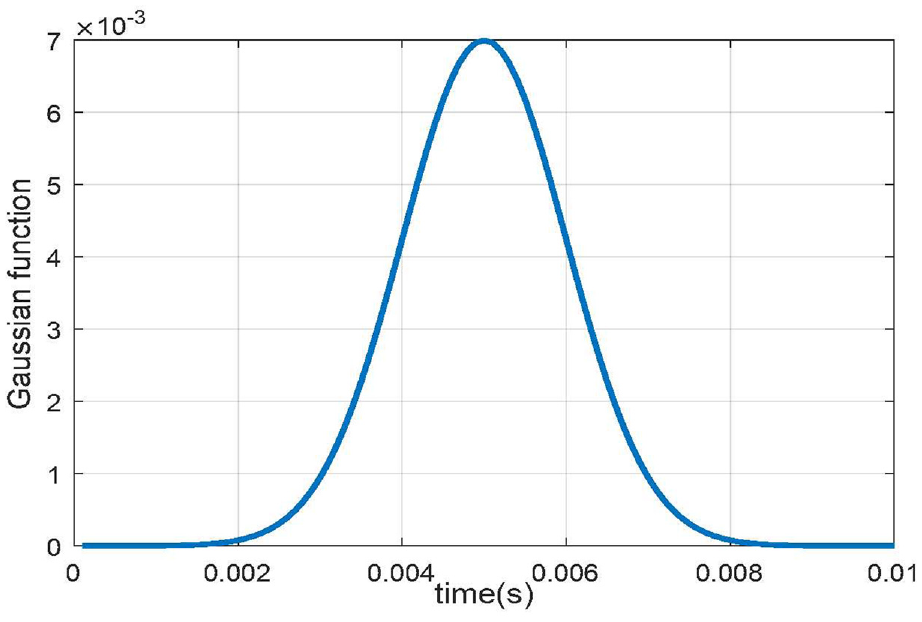
Gaussian white noise normal distribution curve.
Firstly, the sliding mode control correction system of fuzzy switching gain adjustment adopts a sinusoidal input signal with a frequency of 25 Hz and an amplitude of 1°. Its output response is shown in Figure 14:
The output response curve of the sinusoidal input frequency of 25 Hz.
It can be seen from Figure 14 that the steady-state error of the sinusoidal output of the series PD correction system is 0.0165°, and the phase lag is 5.467°. For the sinusoidal response from the fuzzy control correction system, the steady-state error of the output amplitude is 0.0140°. Under the action of the sliding mode controller of fuzzy switching gain adjustment, the steady-state error of the output response from the system is 0°, where two The phase lag difference in the latter is smaller and much smaller than that of the PD series correction system. By comparison, it can be seen that the three control strategies have good control effects on low frequency, and the system with the sliding film control strategy of fuzzy switching gain adjustment has good tracking effect on the input signal, and the results showed that the control strategy makes the system have better dynamic performance.
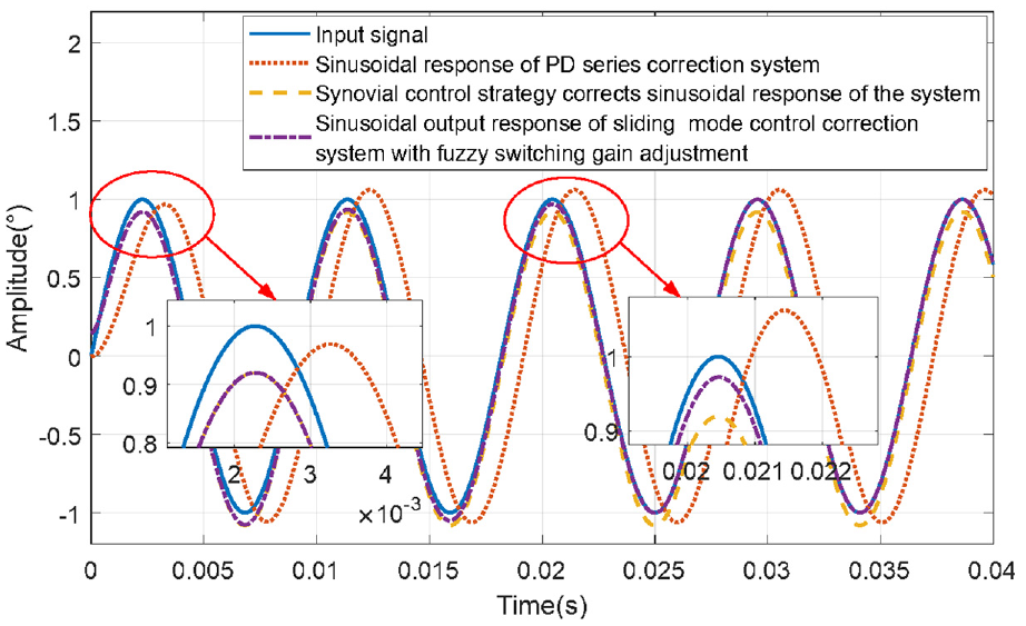
When a sinusoidal signal with an input frequency of 60 Hz and an amplitude of 1° is used as the input signal, the system output response curve is shown in Figure 15:
The output response curve of the sinusoidal input frequency of 60 Hz.
As can be seen from Figure 15, the sinusoidal output error of the series PD correction system is 0.0486°, and the phase lag is 16.1. The sinusoidal response from the fuzzy control correction system has a steady-state error of the output amplitude of 0.0248°. When adopting the sliding mode controller of fuzzy switching gain adjustment, the error of the system output response gradually decreases. Compared with Figure 14 (25 Hz sinusoidal input signal), when the frequency of the input sinusoidal response increases, the dynamic error of the system gradually increases, and the system adjustment time becomes longer.
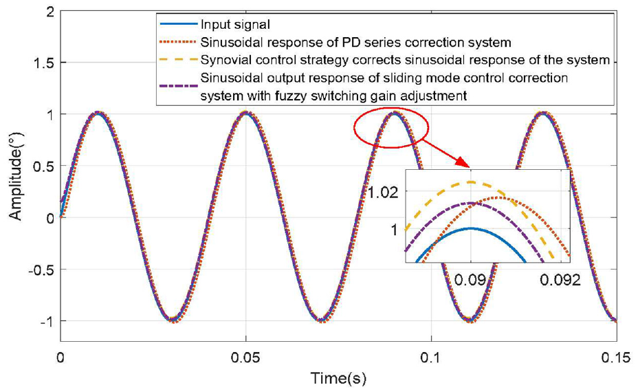
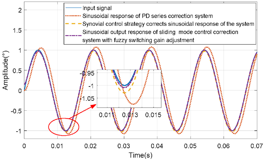
When a sinusoidal signal with an input frequency of 110 Hz and an amplitude of 1° is used as the input signal, the system output response curve is shown in Figure 16:
The output response curve of the sinusoidal input frequency of 110 Hz.
It can be seen from Figure 16 that the sinusoidal output steady-state error of the series PD correction system is 0.0617°, and the phase lag is 39°. For the sinusoidal response from the fuzzy control correction system, the steady-state error of the output amplitude is 0.0803°. When the sliding mode controller of fuzzy switching gain adjustment is adopted, the sinusoidal response error of the system output in the initial response is the same as that of the fuzzy control correction system. And as the response time increases, the synovial control strategy using fuzzy switching gain adjustment can make the steady-state error of the system gradually approached 0. Compared with Figure 15 (60 Hz sinusoidal input signal), when the frequency of the system input signal becomes higher, the steady-state error and phase angle lag behind the series PD and synovial variable structure correction system increase significantly. Among them, the synovial controller of fuzzy switching gain adjustment can eliminate the steady-state error in a short time, and with the increase of the input signal frequency, the time to eliminate the steady-state error gradually becomes longer.
To sum up, it can be seen from Figures 14 to 16 that in this paper, the output response to the corrected system is compared and analyzed by using sinusoidal signals with different frequencies, including PD series controller, sliding mode controller of variable structure of synovium and sliding mode controller of fuzzy switching gain adjustment. The results show that the dynamic performance of the fuzzy control correction system is better than that of the PD series correction system, among which the fuzzy switching gain adjustment sliding mode control correction system has the best dynamic performance, is more suitable for the system to work quickly and accurately at high frequency, and has higher steady-state characteristics.
Conclusion
Footnotes
Declaration of conflicting interests
The author(s) declared no potential conflicts of interest with respect to the research, authorship, and/or publication of this article.
Funding
The author(s) disclosed receipt of the following financial support for the research, authorship, and/or publication of this article: The work of this article was supported by National Natural Science Foundation of China (No. 51405113).