
Abstract
Aiming at the problem that the traditional inverse solution optimization method is not comprehensive and does not consider the robot structure and actual working conditions, an inverse solution multi-objective optimization method is proposed. This method comprehensively considers the structural size and working state of the welding robot, establishes the stiffness performance evaluation index, optimizes the performance index of the subsequent connecting rod movement area caused by joint rotation, and selects the optimal inverse solution combined with the principle of “minimum joint displacement.” Compared with the traditional method, this method is more comprehensive. It makes the variation range of the rear three small joints of the welding robot larger than the front three large joints, which reduces the power consumption. In addition, it also improves the stiffness of the welding robot at the trajectory point, which ensures the reliability of the welding robot. On this basis, for linear and arc welds, the position interpolation of cartesian space line and arc trajectory based on the S-shaped acceleration and deceleration curve and the posture interpolation of spherical linear interpolation based on unit quaternion are realized. MATLAB simulation results show that the combination of the inverse optimization method and the interpolation method makes the end trajectory, velocity, acceleration, posture curve, and joint displacement curve of the welding robot continuous, smooth, and without mutation.
Keywords
Introduction
With the rapid development of modern industrial technology, industrial production lines tend to be intelligent. Most welding production lines, such as automobile and ship manufacturing, have poor working conditions. In order to reduce production costs, improve production efficiency, and ensure welding accuracy, welding robots have become indispensable in welding operations.1,2 Trajectory planning can make the robot move smoothly and reduce impact and vibration, which is of great significance to improving the stability, reliability, and work efficiency of the robot.3,4At present, scholars have conducted research on trajectory planning and have proposed some novel trajectory planning methods, such as the sine resistance network-based planning approach.5,6 But for the welding robot, its trajectory is determined, and the welds of weldments are generally straight lines and arcs. In order to ensure that the welding robot can accurately complete the welding task along the weld, it is necessary to carry out Cartesian space trajectory planning to ensure the stability of the end motion trajectory, so as to improve the welding accuracy and efficiency.7,8 However, the optimal selection of the inverse solution is the basis of trajectory planning.9,10
There are eight sets of inverse solutions for the 6-DOF welding robot. 11 Therefore, choosing appropriate joint variables is the premise of trajectory planning. Wang et al.12,13 used the principle of “shortest stroke” to select a group of joint variables with the smallest variation of front and rear joint angle as the optimal solution. Zhao et al. 14 took the principle of “moving more small joints and fewer large joints” as the influencing factor of the current joint angle, so as to select the optimal solution of the inverse solution. Liu et al. 15 combined with the above principles and set the weighted inverse solution optimization criteria to optimize the inverse solution. However, the above method does not consider the structural characteristics of the robot, the motion state of the robot in actual work, or the minimum requirements of joint angular displacement. Therefore, the optimization principle of the inverse solution is not comprehensive. Duan et al. 16 set the optimization index and optimized the inverse solution by taking the stiffness performance index of the robot and the principle of “moving more small joints and fewer large joints” as the influencing factors, combined with the principle of “shortest stroke.” However, the expression of the principle of “more small joints and fewer large joints” is not combined with the D-H parameters of the robot, so the stroke optimization index is not comprehensive. Wang et al. 17 combined the two influencing factors of joint power consumption and the spatial range of subsequent connecting rod motion sweeping caused by joint rotation with the principle of “shortest stroke,” and proposed a weighted “shortest stroke” criterion to meet the actual work needs of the robot. For joint power consumption, the moving range of the connecting rod behind the joint is equivalent to the ratio of the power consumption of each joint to a certain extent, and the stiffness of the robot in actual work is not considered.
Based on the above literature, an inverse solution multi-objective optimization method is proposed. A group of trajectory points is selected, and the optimization method used in this paper is compared with the traditional inverse solution optimization method to verify the rationality of this method. Based on the inverse solution optimization of the welding robot, the position interpolation of Cartesian space line and arc trajectory based on the S-shaped acceleration and deceleration curve and the attitude interpolation of spherical linear interpolation based on unit quaternion are carried out for linear and arc welds. Finally, the feasibility of the inverse solution multi-objective optimization method and the interpolation method in Cartesian space trajectory planning is verified by MATLAB simulation.
Kinematics analysis
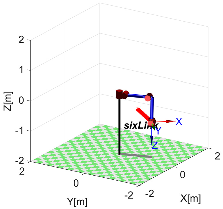
The welding robot is a series robot with only six rotating joints, and the rear three axes intersect at one point. As shown in Figure 1, the coordinate system of the welding robot is established according to the modified D-H parameter method. 18
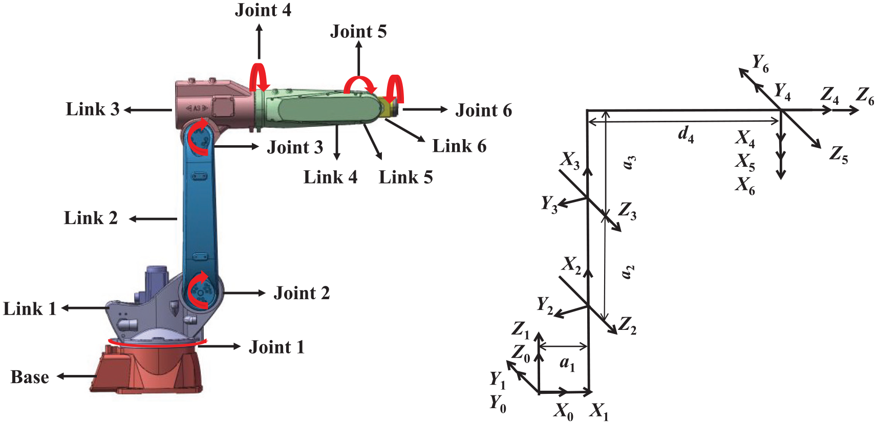
Modified D-H coordinate system.
According to the definition of the D–H connecting rod parameters, the D–H parameters of the welding robot are presented in Table 1. For example, joint angle
D-H parameters of the welding robot.
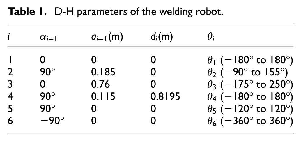
Based on the above parameters, the forward kinematics model can be established and the inverse kinematics solution can be obtained by the method described in Wang and Lam. 11
Optimal selection of the inverse solution
The solution process of the inverse solution of the welding robot shows that there are almost eight groups of analytical solutions for any attitude in its workspace. However, motion planning only needs to select a set of joint variables as the input of the joint. For the traditional optimal solution selection principle, only the motion of small joints is considered, but the relationship with the current joint variables is not considered, or only the principle of minimum joint displacement is considered, while the structure and working conditions of the robot are ignored. The constraints for the optimal selection of the inverse solution are as follows:
Eight sets of joint variables should be within the angle limit of each joint.
Combining with the structure size and working condition of the robot, the inverse solution multi-objective optimization is carried out.
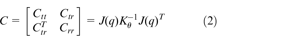
When implementing the welding task for the welding robot, the following connecting rod movement space caused by joint rotation and the stiffness problem of the manipulator in actual work are mainly considered. 19 Therefore, taking them as the influencing factors, the stiffness performance index 20 is shown in equation (1):

Where
Where
For the principle of “more moving small joints and fewer moving large joints,” 14 power minimization is considered without considering the mechanism parameters of the welding robot, as shown in equation (3):
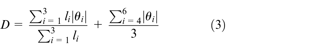
Where
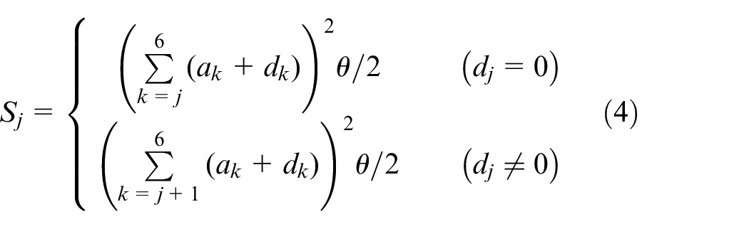
The performance index of the subsequent link motion space caused by joint rotation includes the structural parameters of the robot, so it is more comprehensive than the conventional expression. According to the literature, 17 the optimization index based on standard D-H parameters can be expressed by equation (4).
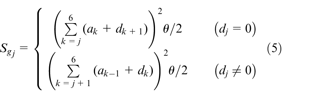
Since the rear three axes of the welding robot intersect at a point, based on the modified D-H parameters, combined with equation (3) and equation (4), the performance indexes of the front three joints can be expressed by equation (5), and The expression of the rear three joints is the same as equation (3).
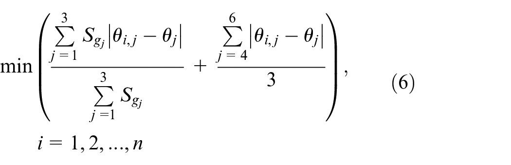
Combining the performance index
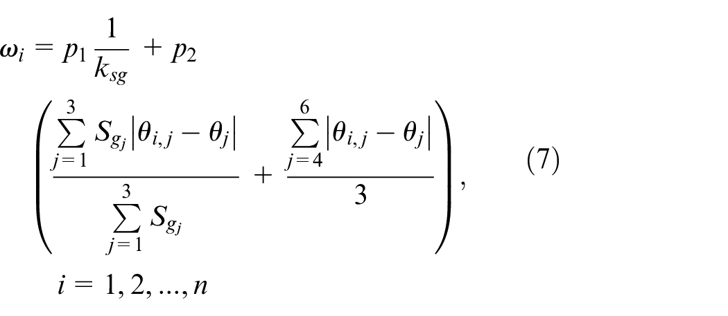
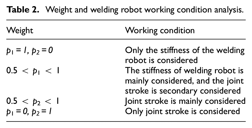
Unify the order of magnitude, set the stiffness index to
Weight and welding robot working condition analysis.
The code idea of optimal selection of the inverse solution is as follows:
Step1: Enter the current joint angle variable
Step2: Using the expression of the inverse solution, the joint variables of the next pose are obtained, and the joint variables
Step3: The multi-objective optimization index
Step4: The joint variables corresponding to the minimum
Step5: Taking the selected optimal solution as
Trajectory planning based on basedon S-shaped acceleration and deceleration curve
The welding robot has strict requirements for the end trajectory, which require that the robot end run according to the specified trajectory and the trajectory be smooth. Therefore, it is necessary to plan the straight-line and arc trajectory of the welding robot in Cartesian space.4,21 In the welding task, the maximum speed and maximum acceleration need to be constrained to make the end trajectory smooth, the speed and acceleration continuous, and reduce the impact on the joint and the loss of the motor. Therefore, on the basis of the inverse solution multi-objective optimization, straight line and circular arc interpolation based on the S-shaped acceleration and deceleration curve are adopted.22–24
S-shaped acceleration and deceleration curve
As shown in Figure 2. Set
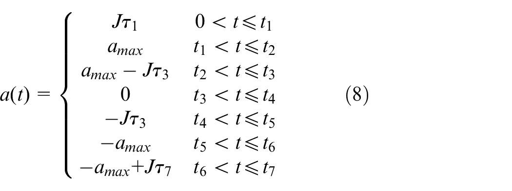
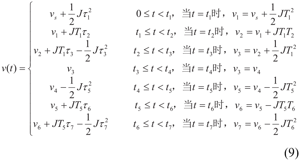
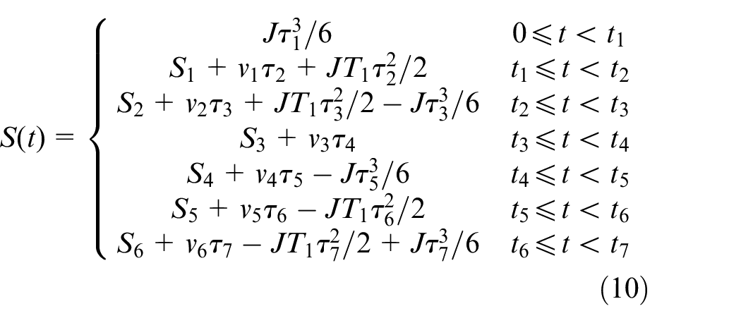
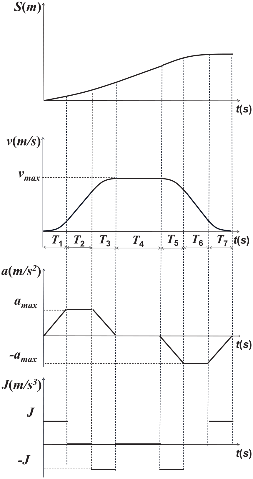
S-shaped acceleration and deceleration curve.
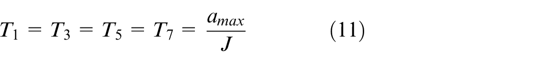
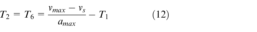
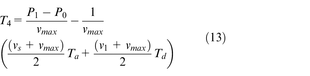
In order to determine the running time of each stage, it is necessary to set the displacement, start and stop speed, maximum speed, maximum acceleration, and acceleration jerk of the S-curve. The operation time of each stage is shown in equations (11)–(13).
The normalized time operator
Where
Position interpolation
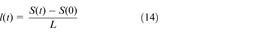
The coordinates of the track start point p0 (x0, y0, z0) and the end point pn (xn, yn, zn) are determined according to the basic coordinate system. Taking the normalized time operator based on the S-shaped acceleration and deceleration curve as the variable, the coordinates pi (xi, yi, zi) of the interpolation point can be expressed by equation (15):
In the base coordinate system, set the coordinates of the arc start point, midpoint and end point as p1 (x1, y1, z1), p2 (x2, y2, z2), and p3 (x3, y3, z3). The three points are in the same 3D space, but not on the same line.
As shown in Figure 3. According to the method in Corradini and Cristofaro,
26
the center coordinate
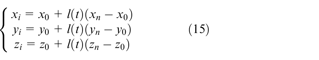
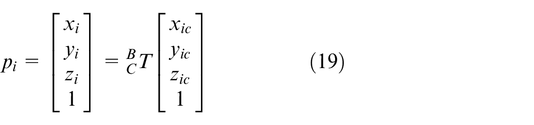
Calculate the conversion matrix
As shown in Figure 4. Calculate the center angle
Taking radian as L, the normalized time operator
Combining with the normalized time operator, arc interpolation can be shown by formulas (16)–(19).


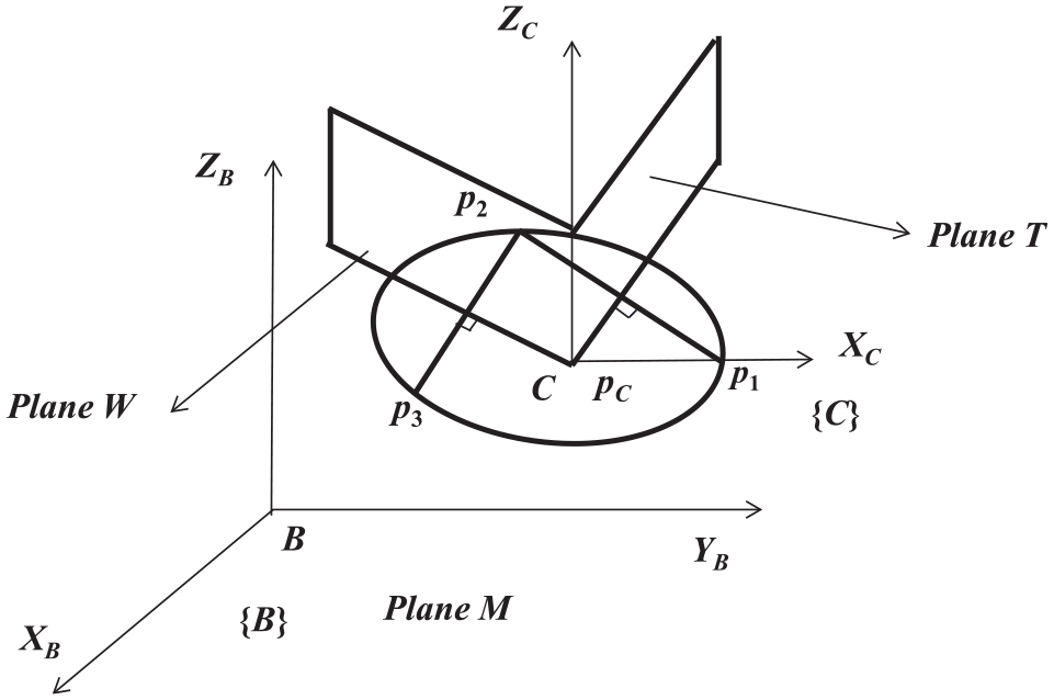
Arc center.
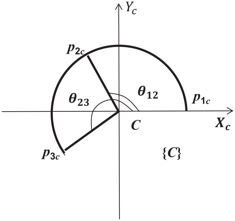
Arc radian.
Attitude interpolation
Compared with other representations of attitude, unit quaternion has the advantages of simple operation, no universal joint locking, and easy interpolation. Therefore, the spherical linear interpolation (SLERP) method based on unit four elements is used for attitude interpolation. 27
Set the quaternion to
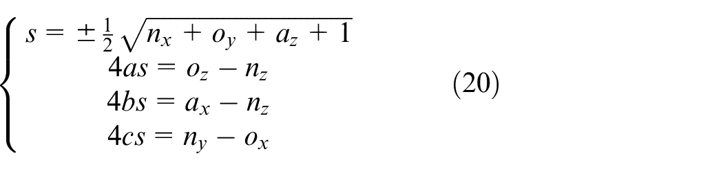
Set the attitude matrices of the starting point and the ending point as R1, R2 respectively. The quaternion

The pose between two points can be obtained by the SLERP method. 28
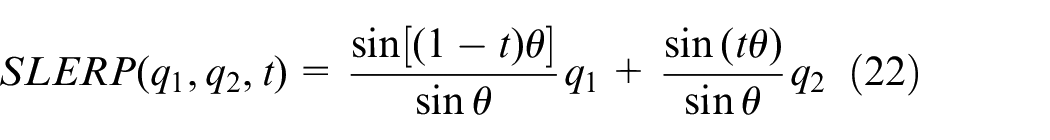
Where t is the normalized time operator
If the value of the quaternion dot product is negative, it will be interpolated to the farthest path on the 4D sphere. In order to deal with this drawback, the value of the dot product is calculated first. When it is negative, any one of the two quaternions is taken as the inverse (it will not change its direction). Through the above processing, interpolation can be done on the shortest path.
Simulation results and discussion
The position where the joint angle is 0 is taken as the starting position, and a series of trajectory points are obtained by quintic polynomial interpolation. The optimization index formed by the combination of the performance index
Performance superiority analysis of optimization index
The complexity of the algorithm is divided into time complexity and space complexity. The welding robot is a real-time system, and the system response requirements are high. So the algorithm

T(n) represents the execution time of the code; n represents the size of the data size; f(n) represents the total number of executions per line; O represents the trend of code execution time with the increase of data scale, also known as progressive time complexity.
The time complexity of the algorithm
The execution time of the three algorithms is shown in Figure 5.
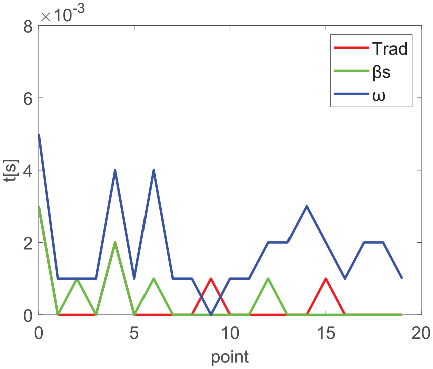
Execution time.
As shown in Figure 5 the execution time of the three algorithms has little difference, and the order of magnitude of the execution time of the algorithm
As shown in Figures 6 and 7 in order to further analyze the superiority of the optimization index
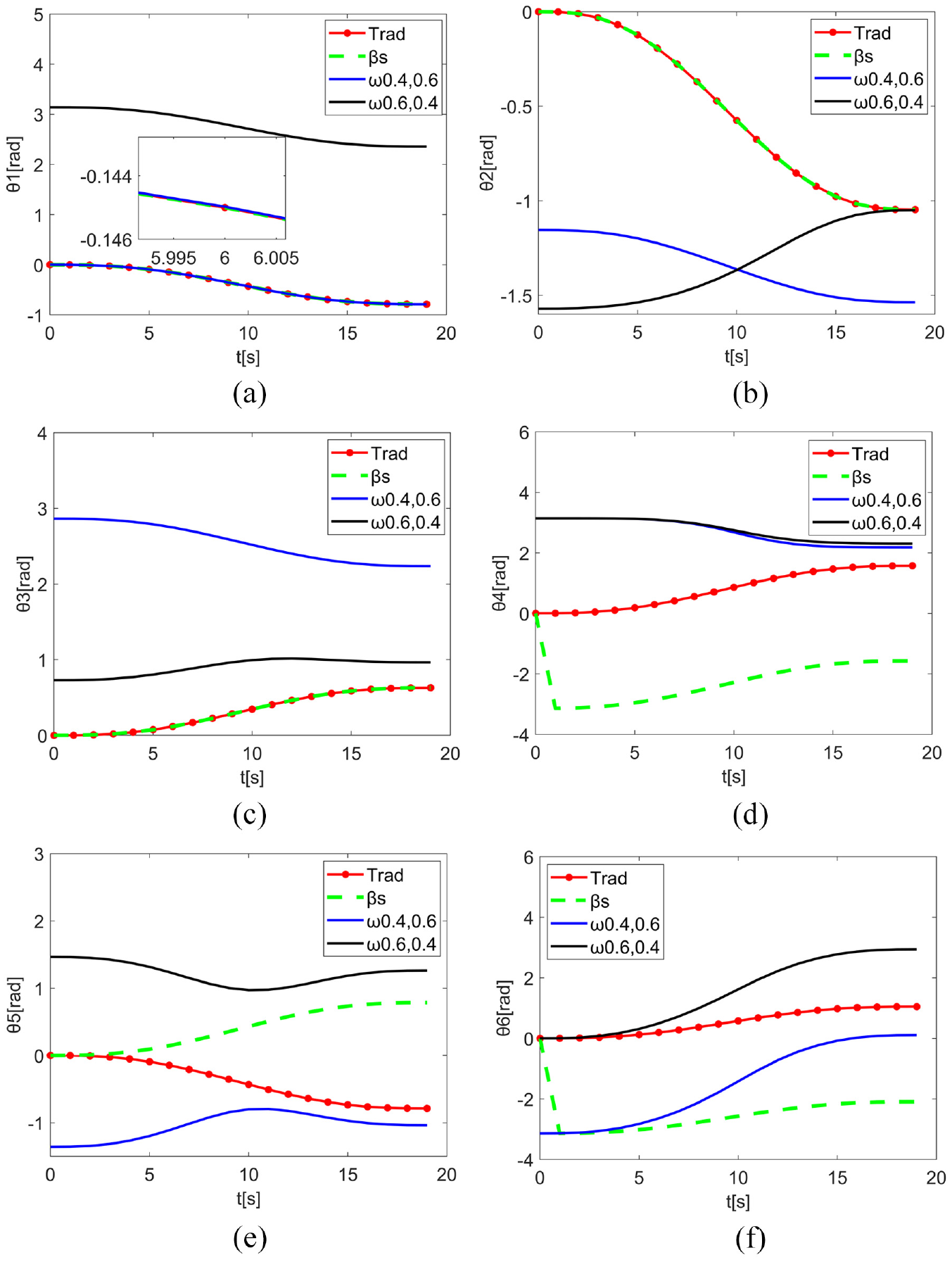
Comparison of joint variables: (a) joint 1, (b) joint 2, (c) joint 3, (d) joint 4, (e) joint 5, and (f) joint 6.
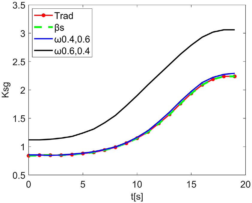
Stiffness contrast.
In ADAMS software, the welding robot model is constructed, and the variation of the above joints is taken as the input to measure the power consumption of the welding robot under different optimization indexes. The results are shown in Figure 8.
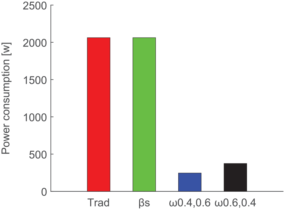
Power consumption of welding robot.
Figures 6 and 7 show that, firstly, in the initial position, according to the weight setting of the optimization index
Trajectory simulation
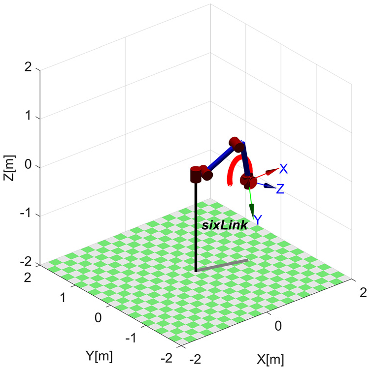
MATLAB is used to complete the motion trajectory interpolation simulation of the welding robot.29–31 The simulation idea is shown in Figure 9.
(1) Linear interpolation simulation
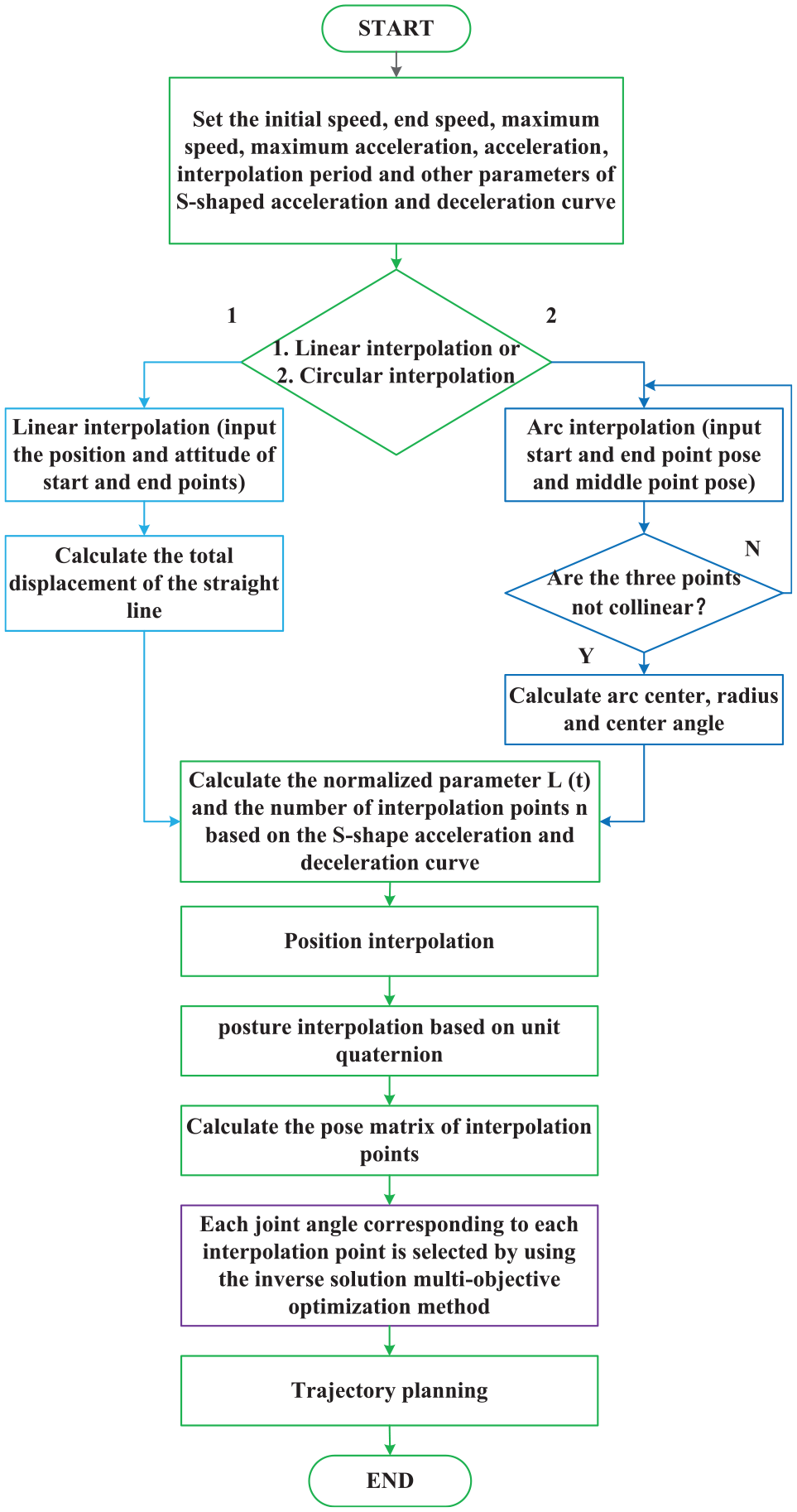
Trajectory planning flowchart.
The pose matrix of the start point p1 and the end point p2 is set as follows:
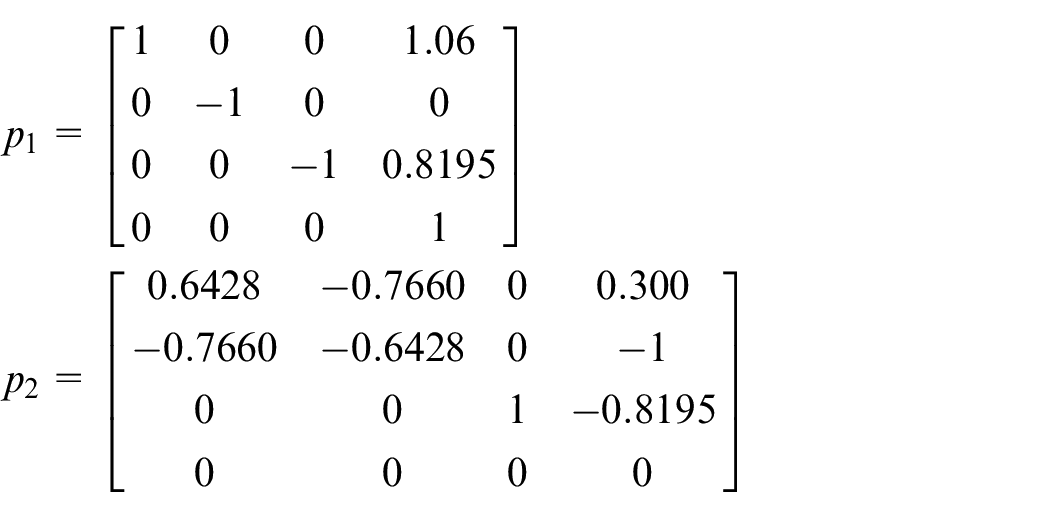
The corresponding quaternions
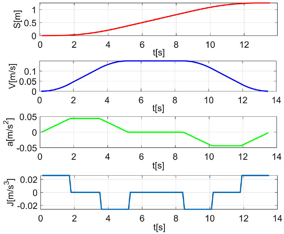
Motion state of the end.
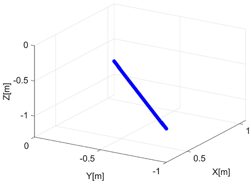
Spatial linear trajectory.
Linear interpolation.
Variation curve of each joint.
The attitude quaternion is converted into XYZ Euler angle. The end attitude change curve is shown in Figure 14.
(2) Circular interpolation simulation
Variation curve of end attitude.
Set the homogeneous transformation matrix of three points on the arc as follows:
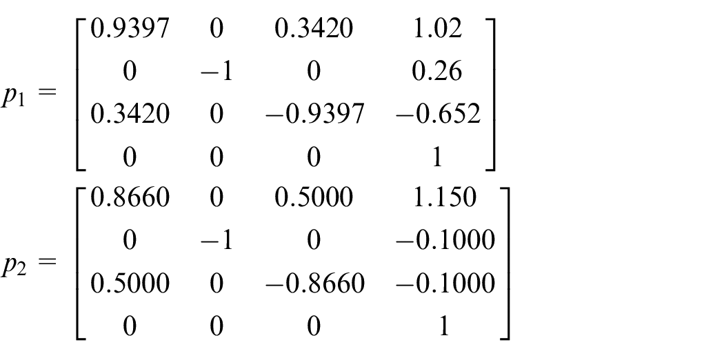
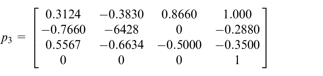
The quaternions are
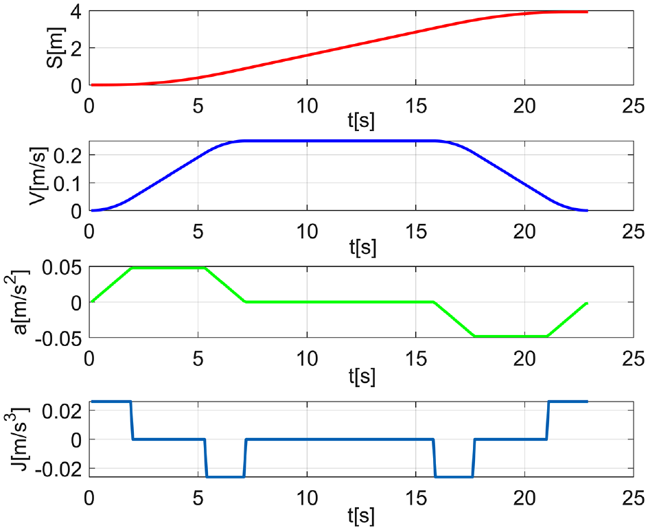
Motion state of the end.
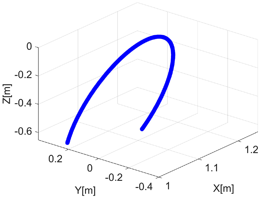
Space curve trajectory.
Linear interpolation.
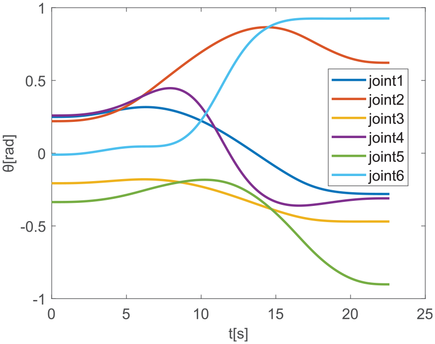
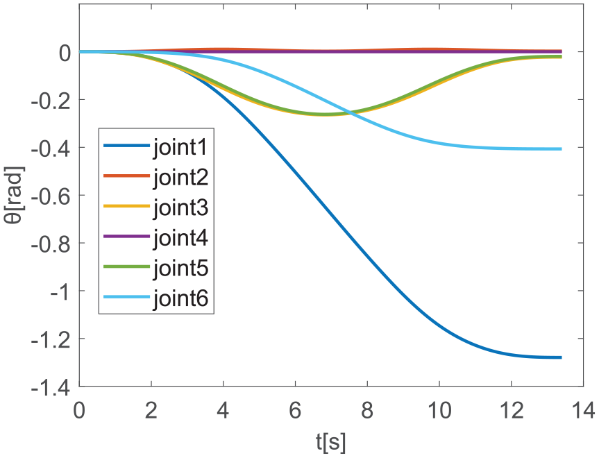
Variation curve of each joint.
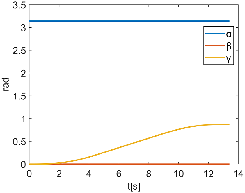
The attitude quaternion is converted into XYZ Euler angle. The end attitude change curve is shown in Figure 19.
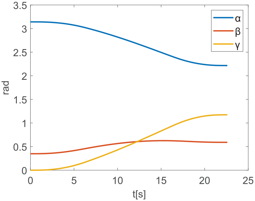
Variation curve of end attitude.
Figures 11 and 16 show that the trajectory planning method can make the welding robot complete the specified straight and circular trajectory. Figures 10 and 15 show that the end of the welding robot can complete the welding task according to the set velocity constraint curve, and the displacement, velocity, and acceleration of the end are flat without mutation, which verifies the feasibility of the spatial trajectory interpolation based on the S-shaped acceleration and deceleration curve and improves the working performance of the welding robot. Figures 14 and 19 show that the spherical linear interpolation (SLERR) based on unit quaternion ensures the stability of the end attitude of the welding robot and avoids the singularity of the attitude. Figures 13 and 18 show that each joint variable of the welding robot is gentle and has no mutation, and the variation range of the rear three small joint variables is greater than that of the front three large joint variables, which verifies the feasibility of the combination of the inverse solution multi-objective optimization method and the trajectory planning method.
Conclusion
In this paper, the performance evaluation index of the connecting rod stiffness is established, and the performance index of the subsequent motion area of the connecting rod caused by joint rotation is improved. Based on the principle of minimum joint displacement, an inverse multi-objective optimization method is proposed. Compared with traditional methods, it is more comprehensive. To a certain extent, this method makes the post-triaxial variables continuously non-mutation, and the angle variation of the rear three small joints is greater than that of the front three large joints, which reduces the power consumption of the welding robot. In addition, the multi-objective optimization index
Prospect: In the future, the inverse multi-objective optimization problem will be further studied to achieve the optimal solution from the inverse operation itself and, on this basis, deepen the trajectory planning.
Footnotes
Declaration of conflicting interests
The author(s) declared no potential conflicts of interest with respect to the research, authorship, and/or publication of this article.
Funding
This research was funded by High-Tech Ship Scientific Research Project from the Ministry of Industry and Information Technology ([2019]360) and Zhengzhou University Youth Talent Enterprise Cooperative Innovation Team Support Program Project (2021).