
Abstract
The inconsistency between continuous feedrate scheduling and discrete interpolation of Non-Uniform Rational B-Splines (NURBS) curves as toolpath interpolation affects the interpolation accuracy and motion smoothness of computer numerical control (CNC) machining. The S-shaped series feedrate scheduling method of the NURBS curve is presented to meet the consistency between feedrate scheduling and interpolation, and the needs of the motor to receive accurate discrete pulses to avoid chatter. The acceleration and deceleration margin factor models are respectively established in the acceleration and deceleration stages to compensate for the velocity loss in the discrete process, so that the feedrate scheduling can be accurately reached in each acceleration and deceleration stage. Based on this, 17 kinds of acceleration and deceleration situations are summarized according to the comparison of displacement, start and end velocity, and the number of interpolation cycles. The butterfly three-segment trajectories are selected for simulation in Matlab. The experimental platform is built based on the Codesys platform programing, and the series feedrate scheduling of the proposed method for a NURBS toolpath is carried out. Both simulations and experiments have verified the effectiveness of the algorithm.
Keywords
Introduction
The International Organization for Standardization (ISO) defined NURBS 1 as the only mathematical representation for free curve surfaces, defined in the Standard for the Exchange of Product Model Data (STEP) in 1991. Subsequently, it is incorporated into the international standard of Programmers Hierarchical Interactive Graphics System (PHIGS). After this, the NURBS has been extensively applied in numerical control machining of complex parts.2–5 In order to effectively reduce the impact, desynchronization, overtravel or oscillation of the machine tool during CNC machining, acceleration and deceleration control is required for the feedrate scheduling. 6 Feedrate scheduling is divided into pre-interpolation and post-interpolation scheduling. With the development of computer technology, pre-interpolation feedrate scheduling is mainly used.
The curve and surface represented by NURBS have full flexibility, and at the same time, the representation of elementary curve and surface, free-form curve and surface are unified. But it still has shortcomings: the parameters have no geometric meaning and there is no analytical expression for calculating arc length. Usually arc length calculation of free-form curve is to approximate the arc length with the chord length, but the error is large. Jeon and Ha 7 calculates the radius of curvature of the point and approximates the length of the curve with the arc length. The solution process is an iterative method, which requires a large amount of calculation and is not conducive to real-time calculation. Jun et al. 8 proposed a high stationary control strategy for the theoretical basis of the kinematic stability of numerical control equipment. Lin et al. 9 studied the five-section S-shaped acceleration and deceleration control algorithm for real-time interpolation of NURBS curves. Pan et al. 10 studied the S-shaped acceleration and deceleration control algorithm, and 17 S-shaped type acceleration and deceleration modes were given to achieve continuous acceleration and deceleration, and to reduce shock and oscillation. Sun et al. 11 used the real-time interpolation algorithm for flexible high-speed machining via adjusting the acceleration of the axis of motion up to the requirement of continuous transition. Adaptive feedrate scheduling for continuous parametric toolpath with confined contour error and axis jerks was proposed by Chen et al. 12
Liu et al.13,14 proposed adaptive feedrate scheduling on parametric toolpath with geometric and kinematic constraints for CNC machining. Lee et al. 15 proposed an off-line feedrate scheduling method for CNC machines constrained by chord tolerance, acceleration and jerk limitations. Su et al.’s team has developed successively the trajectory is partitioned into feedrate restricted intervals (FRIs) determining the target feedrate and the positions of tool acceleration and deceleration on the toolpath, 16 and proposed a feedrate optimization method of end milling using the internal data of the CNC system, that is, the spindle power, the block number, and the combined speed of feed axes. 17 A novel jerk minimization algorithm in the context of multi-axis flank CNC machining is proposed by Hashemian et al., 18 in which the total jerk of the tool’s motion is minimized, implying the tool is moving as smoothly as possible, without changing the geometry of the given toolpath. Zhong et al. 19 proposed a novel real-time interpolator for parametric curves (RTIPC), which provides a time-optimal solution and limits the machine dynamics (axial velocities, accelerations and jerk) and contour error through feedrate look ahead and acceleration look ahead operations. Sun et al. 20 present a state-of-the-art review: path, feedrate and trajectory planning for free-from surface machining. Lin et al. 21 proposed a combined feedrate scheduling model with error constraints as well as dynamic constraints, and an efficient algorithm is designed to solve this model.
As discussed above, the feedrate scheduling algorithm is proposed using the continuous integration approach. Furthermore, the motion factors such as velocity at the time of actual interpolation are solved from the step changes of the corresponding discreteness. A time-rounding-up based feedrate scheduling method is proposed to consider the round-off error while restricting the motion parameters within their specified ranges by Ni et al. 22 In this paper, a new “S-shaped Series” feedrate scheduling algorithm is developed to compensate for the velocity losses in the discrete process based on the relevant velocity margin factor. The purpose is to use known acceleration and deceleration in the acceleration and deceleration stages when the toolpath is sufficiently long under normal circumstances, and add an acceleration interpolation cycle in which the velocity reaches the known maximum velocity.
In the first section, the acceleration and deceleration modes with the discrete process under various circumstances are summarized. Secondly, acceleration, velocity, and displacement of discretization are solved from the interpolation cycle as the velocity step changes. The velocity losses of the discrete process can be compensated by the velocity margin factor. In addition, the S-shaped series acceleration and deceleration motion is proposed based on the NURBS curve. This method has fulfilled the discreteness requirement of the actual interpolation which can further improve the computational efficiency and real-time requirement for CNC machining.
Velocity, displacement, and interpolation cycles based on S-shaped series algorithm
Interpolation cycles of the S-shaped series algorithm
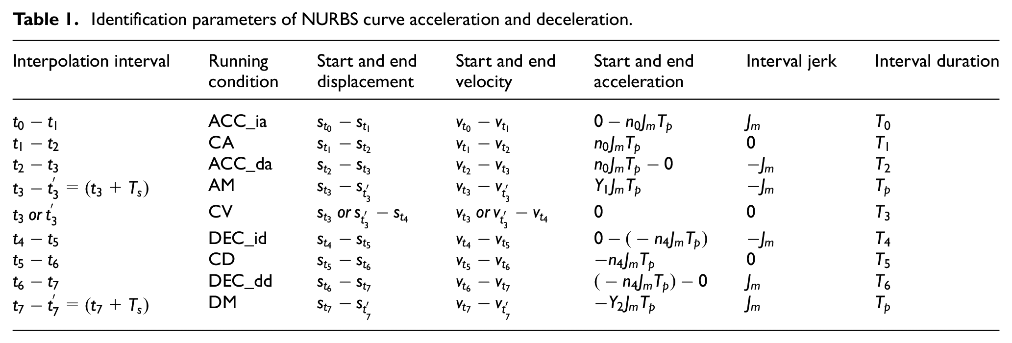
During CNC interpolation, NURBS curve interpolation can be performed to guarantee the discreteness of velocity. Moreover, displacement, velocity, acceleration and deceleration motion of the seven-section S-shaped is shown in Figure 1.

Acceleration and deceleration process of NURBS curve.
In this figure,
Identification parameters of NURBS curve acceleration and deceleration.
Suppose

① When
② When
③ When
④ When
If

Where,
Displacements at acceleration and deceleration sections of S-shaped series algorithm


Moreover,

After that, the displacement

Similarly, the displacement

The displacement of constant deceleration at the deceleration section such as

The displacement of the deceleration margin factor section (

Finally,

Moreover, the non-uniform velocity section has a displacement of

Arc length and maximum velocity of S-shaped series algorithm
The arc length of the NURBS curve adopts the Gaussian integration method. Gaussian numerical integration is an effective high-precision numerical calculation method. In the field of engineering numerical calculations, it is commonly used to perform numerical calculations on integrals that are difficult to obtain analytical solutions. At the same time, the Gaussian integral is widely used due to their computational stability and convergence.
The Gaussian integral of n nodes can be expressed as 23 :

The larger the value of n, the more accurate the calculation result. Literature 11 introduced the method of selecting nodes and weighting factors of the Gaussian integral formula.
In this paper n = 3, that is,
From the differential geometry, the interval between two adjacent sampling points

Velocity

Where

The maximum velocity

Where
Method for S-shaped series acceleration and deceleration modes
17 Acceleration and deceleration modes of seven-section S curve
An integral velocity curve mode is presented in Figure 1, obtained at long processing distance where the corresponding velocity reaches its maximum value. When the start velocity  represents the uniform acceleration stages, the symbol
  represents the variable acceleration stages, and the symbol
  represents the uniform velocity stages.

17 Modes of S-shaped series acceleration and deceleration ( uniform acceleration stage,  : variable acceleration stage,
  : uniform velocity stage).
Computational formulas for the interpolation cycles of the corresponding 17 acceleration and deceleration modes are listed in Table 2.
Interpolation cycles for the computation of 17 acceleration/deceleration modes.

The rounding down
Flow chart analysis of 17 acceleration and deceleration modes
To analyze the 17 acceleration/deceleration modes, the following procedure is employed.
Judge the size of
Figure out
Judge the size of
Figure out interpolation cycles from equation (1) and (2)
Select the acceleration/deceleration mode, to complete planning for curves.
Detailed judgment procedures are considered for four situations Vs = Vd = Vm, Vs < Vd = Vm, Vd <Vs = Vm and
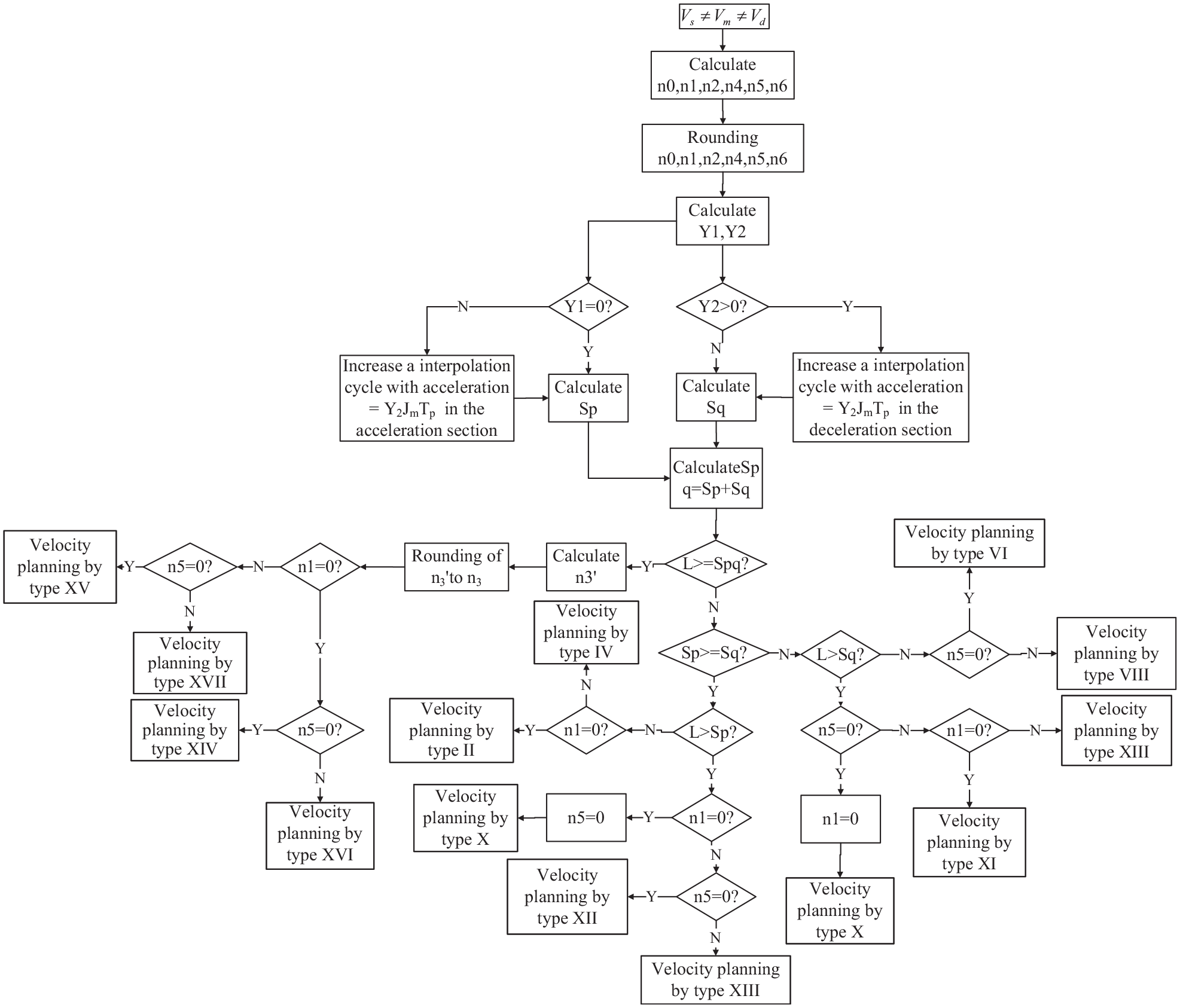
The general situation
Different symbols such as
Simulation and experiment
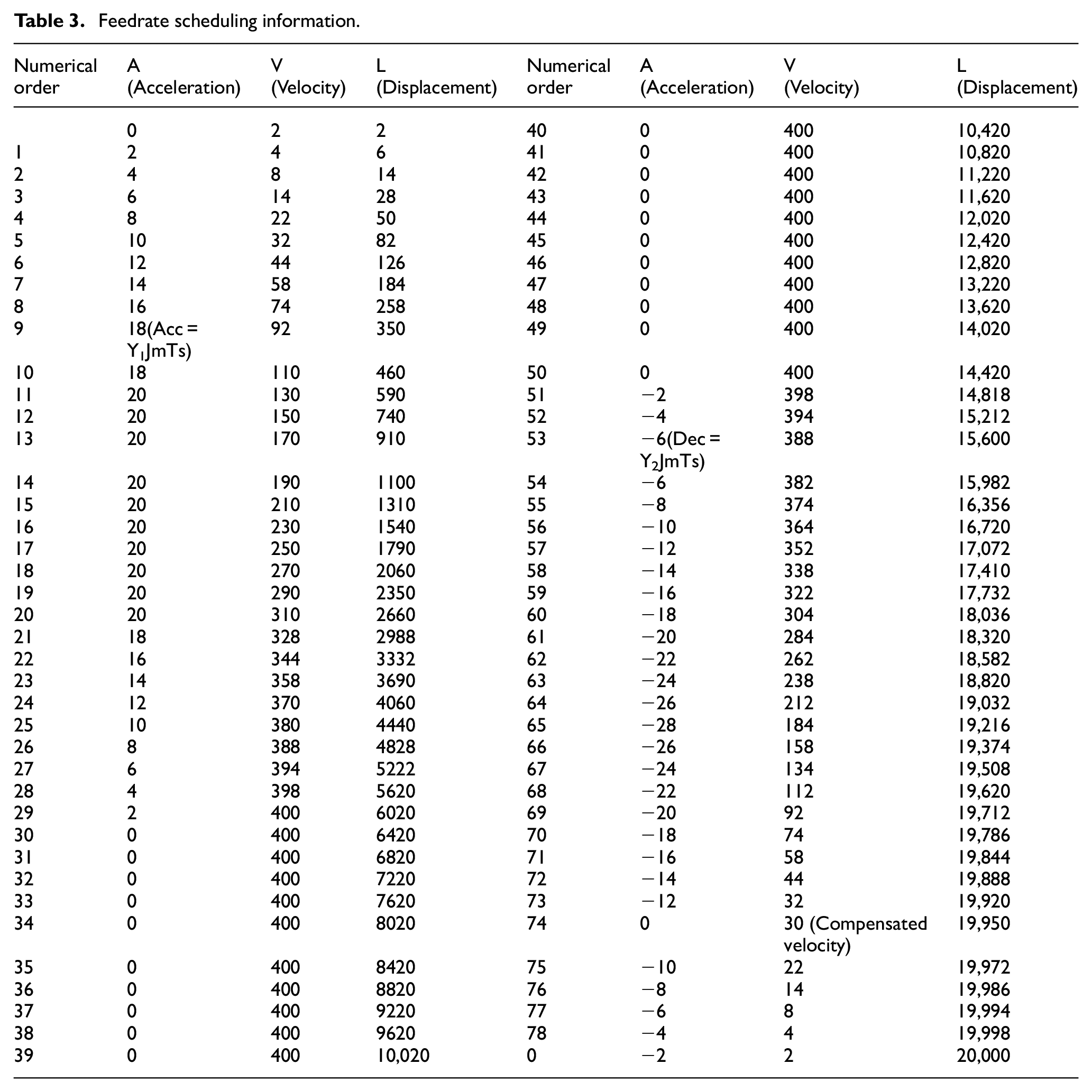
Assuming NURBS curve 20,000 mm, it is known that the start velocity
Using the S-shaped series feedrate scheduling proposed in this paper, it is calculated that increasing acceleration
Feedrate scheduling information.

Acceleration, velocity, and displacement trajectory.
It can be obtained from the table that in the acceleration phase, the acceleration as the rounding loss is realized by compensating the acceleration
In order to further verify the effectiveness of the algorithm, the butterfly is used as the tool path for feedrate scheduling as shown in Figure 5. The specific butterfly fitting parameters are listed in the Appendix. The I, II, and III trajectories are chosen as the planning trajectories, and the previous formula (13) is used to calculate of each arc. The formulas (14)–(16) calculate the start and end velocity. During the Matlab simulations, the S-shaped series acceleration/deceleration mode judgment methods of NURBS butterfly curves are determined. The motion parameters are defined as the values of maximum velocity

The butterfly toolpath.
I trajectory is calculated with start velocity
II trajectory is calculated with start velocity
III trajectory is calculated with start velocity
The acceleration, velocity and displacement trajectories are shown in the Figures 6 to 8 respectively. The symbol o means adding an acceleration caused by rounding acceleration in an interpolation cycle to make the velocity reach the known maximum velocity in the acceleration stage. The symbol  performs compensated velocity caused by rounding velocity to reach accurately the end.

Acceleration trajectory.

Velocity trajectory.

Displacement trajectory.
The test platform is composed of programing software, a master station, a slave station, a real-time Ethernet bus, a drive and a motor as shown in Figure 9. Real-time Ethernet adopts the high-performance NCUC 2.0 bus protocol with a communication cycle of 1 ms. Logic programing software and HMI monitoring software run on the upper computer, and perform Modbus or TCP/IP communication with the system master to complete the control program code download and real-time data interaction. The master station module is the core of the system logic program execution and task scheduling. It mainly performs the calculation of the compiled IEC 61131 logic program, the data communication between the slave nodes based on real-time Ethernet, and the data exchange of the human-computer interaction interface. The slave station is the main part of the system that directly completes the control of the peripheral equipments. It mainly performs real-time communication with the master station, and realizes real-time control functions such as digital/analog data acquisition and output, and motor servo. The digital AC servo drive is a high-end AC servo system with high performance, intelligence, high reliability, and small size. It adopts a dedicated digital signal processor (DSP) and an intelligent power module (IPM), an advanced and optimized control algorithms that can achieve accurate digital control of torque, velocity and position. Huada LDD series servo motors have a short dynamic response time, stable operation at low velocity, and realizes closed-loop control of position, velocity and torque.

The test platform.
The semicircle curve is shown in Figure 10(a) and constructed by a 2nd degree B-Spline with control points = (0 0 0,0 100 0,−100 100 0,−100 0 0), knot vector = (0 0 0 0 1 1 1 1), and weights = (1 1/3 1/3 1). The acceleration, velocity and displacement planning with the proposed method is shown in Figure 11. Figure 10(b) shows the interpolation results of the semicircle curve, and the interpolation points can be zoomed on the trajectory for the partial view. Through the trace function of codesys, the velocity and displacement trajectory of the X axis and Y axis are shown in Figure 12.
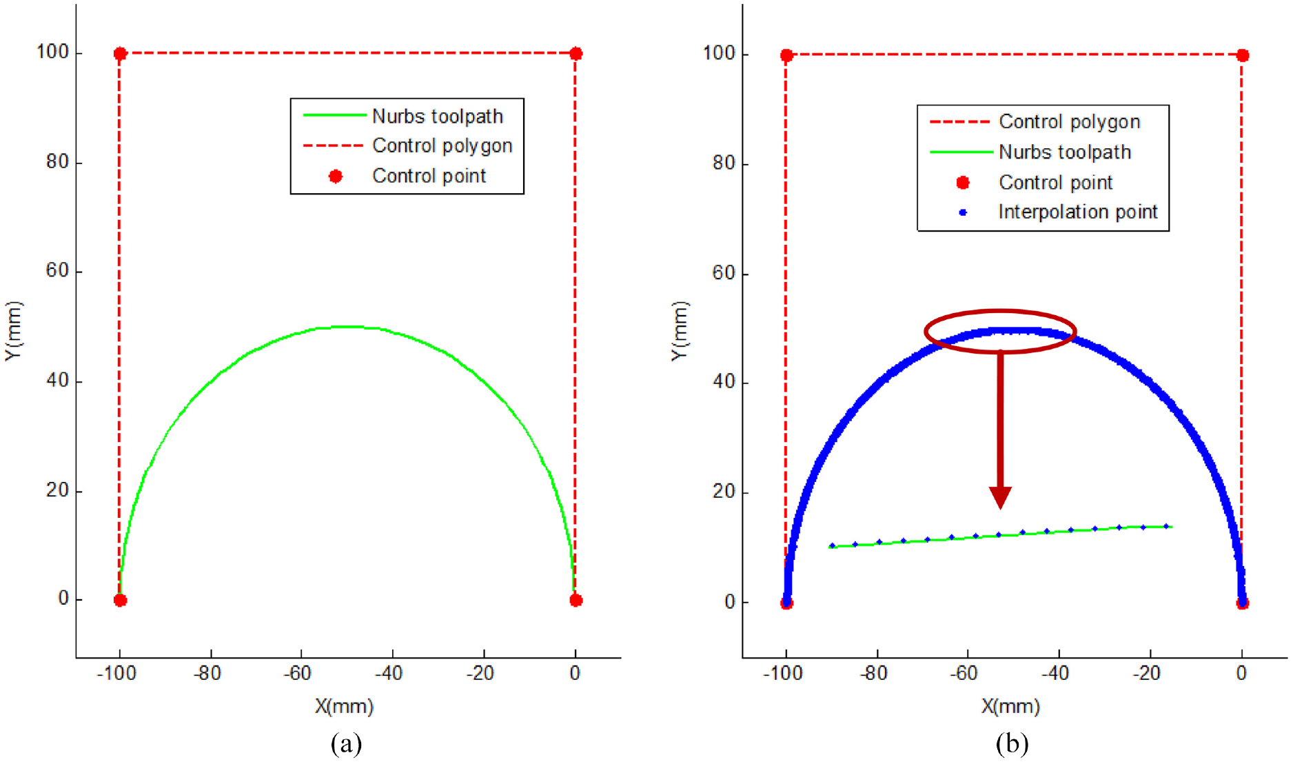
NURBS toolpath and interpolation.

Acceleration, velocity and displacement trajectory.
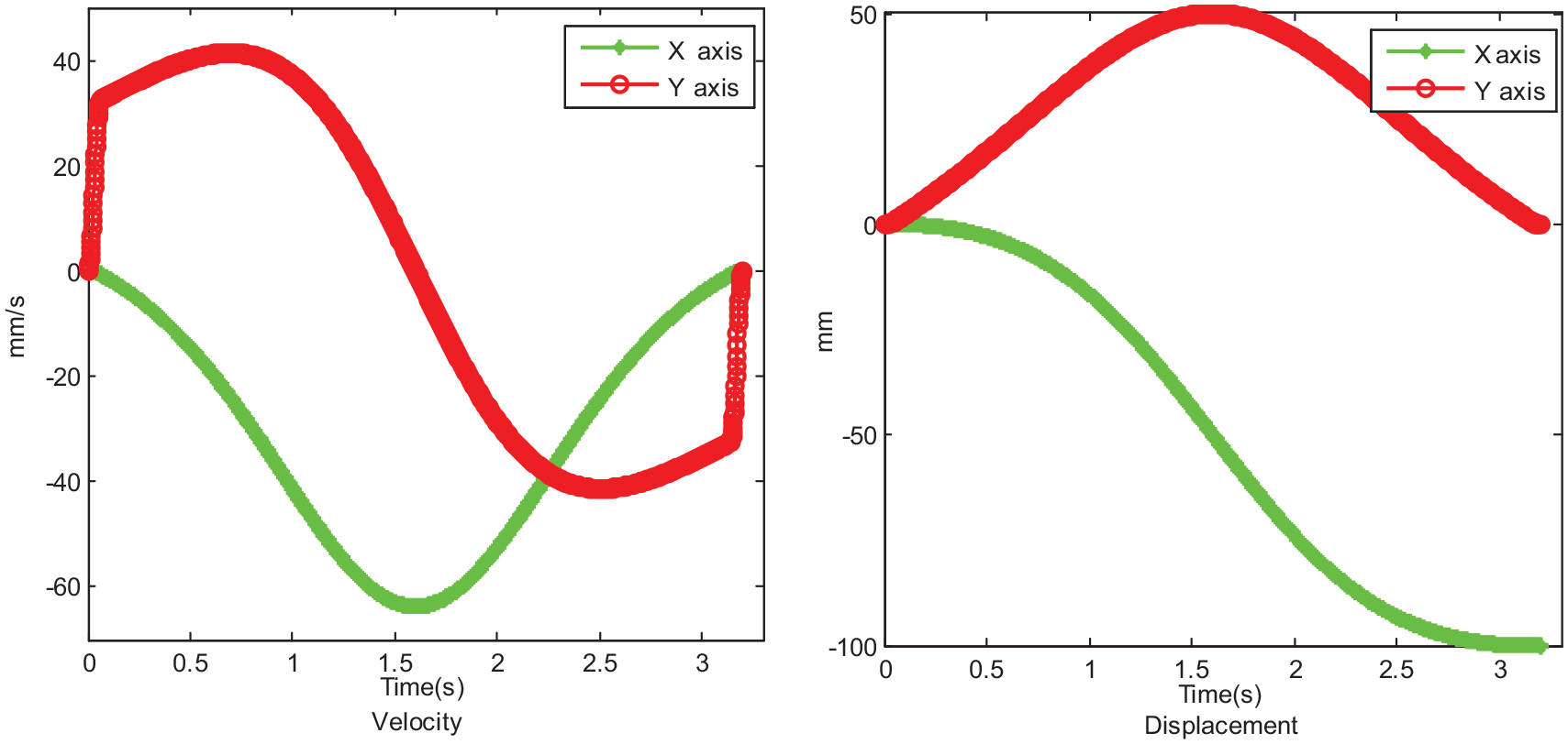
Velocity and displacement of X and Y axis.
Conclusions
In the acceleration and deceleration stage, in order to compensate for the loss of acceleration and deceleration rounding, the acceleration
The experimental platform is built and programing is based on the CODESYS platform. The series feedrate scheduling of the proposed method for the semicircle curve is carried out through the software configuration. The interpolation trajectory shows that the proposed method feedrate scheduling can guide the toolpath trajectory to reach the end point accurately
Footnotes
Appendix
The butterfly coordinates for control points (54.493, 52.139), (55.507, 52.139), (56.082, 49.615), (56.780, 44.971), (69.575, 51.358), (77.786, 58.573), (90.526, 67.081), (105.973, 63.801), (100.400, 47.326), (94.567,39.913), (92.369, 30.485), (83.440, 33.757), (91.892, 28.509), (89.444, 20.393), (83.218, 15.446), (87.621, 4.830), (80.945, 9.267), (79.834, 14.535), (76.074, 8.522), (70.183, 12.550), (64.171, 16.865), (59.993, 22.122), (55.680, 36.359), (56.925, 24.995), (59.765, 19.828), (54.493, 14.940), (49.220, 19.828), (52.060,24.994), (53.305, 36.359), (48.992, 22.122), (44.814, 16.865), (38.802, 12.551), (32.911, 8.521), (29.152, 14.535), (28.040, 9.267), (21.364, 4.830), (25.768, 15.447), (19.539, 20.391), (17.097, 28.512), (25.537, 33.750), (16.602, 30.496), (14.199, 39.803), (8.668, 47.408), (3.000, 63.794), (18.465, 67.084), (31.197, 58.572), (39.411, 51.358), (52.204, 44.971), (52.904, 49.614), (53.478, 52.139), (54.492, 52.139); knot vectors (0, 0, 0, 0, 0.0083, 0.0150, 0.0361, 0.0855, 0.1293,0.1509, 0.1931, 0.2273, 0.2435, 0.2561, 0.2692, 0.2889, 0.3170, 0.3316, 0.3482, 0.3553, 0.3649, 0.3837, 0.4005, 0.4269, 0.4510,0.4660, 0.4891, 0.5000, 0.5109, 0.5340, 0.5489, 0.5731, 0.5994, 0.6163, 0.6351, 0.6447, 0.6518, 0.6683, 0.6830, 0.7111, 0.7307, 0.7439, 0.7565, 0.7729, 0.8069, 0.8491, 0.8707, 0.9145, 0.9639, 0.9850, 0.9917, 1, 1, 1, 1); weights (1,1,1,1,1,1,1,1,1,1,1,1,1,1,1,1,1,1,1,1,1,1,1,1,1,1,1,1,1,1,1,1,1,1,1,1,1,1,1,1,1,1,1,1,1,1,1,1,1,1,1).
Handling Editor: Chenhui Liang
Contributions
Wu Jichun is mainly responsible for writing and revising papers and algorithm design. Xu Ke mainly writes papers and experimental platform construction and experimental verification. Ren Guang is mainly responsible experimental guidance. Fan Dapeng is mainly responsible for overall guidance. I would like to take this opportunity to thank the reviewers for their comments and the editors for their revisions to the article.
Declaration of conflicting interests
The author(s) declared no potential conflicts of interest with respect to the research, authorship, and/or publication of this article.
Funding
The author(s) disclosed receipt of the following financial support for the research, authorship, and/or publication of this article: Supported by the Regional Innovation Foundation of China-Hunan Joint(U19A2072), National Natural Science Foundation of China (52105077), the Natural Science Foundation of Hunan Province (2021JJ30678).