
Abstract
The numerical simulation of casting process can calculate casting filling process, solidification process, and obtain change and coupling information of temperature field, velocity field, pressure field, stress field and microstructure. At present, numerical simulation of casting process has been quite mature at the macro level, and is developing towards the direction of micro level. The coupling and integration of different fields between temperature, flow, stress, and microstructure, is the shape of things for numerical simulation research of casting process. This paper reviews and summarizes the research history and current situation of numerical simulation of casting process. The progress in numerical simulation from five aspects of casting solidification, casting filling, stress field, microstructure, commercial software, is presented.
Introduction
The numerical simulation of casting process numerically calculates and simulates the filling flow and solidification process of liquid metal in mold, so as to obtain the changes of temperature, flow, pressure, and microstructure of castings in casting process. The numerical simulation of casting formation can predict defects, including shrinkage cavity, shrinkage porosity, hot crack. The simulation results can be used for optimization of casting process parameters, eliminating casting defects and improving product quality. The qualities of different process schemes can be predicted and compared ahead of production through casting numerical simulation software, so as to reduce the cost and development time of new products. Therefore, the numerical simulation of casting process can shorten the process experiment cycle, ensure the casting quality, improve the process yield, reduce the production cost and waste loss, and has high practical value for enterprises.
Numerical simulation of casting process mainly consists of temperature simulation, flow simulation, stress simulation, and microstructure simulation. 1 The casting solidification simulation began from the 1960s. The mold filling and stress-strain evolution began in the 1980s. In the 1990s, it entered the numerical simulation of casting microstructure. At present, numerical simulation of casting process has penetrated into all aspects of casting forming process, and is developing towards microstructure simulation, performance optimization and service life prediction. The paper discusses the status and trend of casting simulation from the following five aspects: solidification, filling, stress, microstructure and simulation software.
Simulation of casting solidification
After the high-temperature liquid metal is filled in the mold, it releases heat, and gradually cools and solidifies, finally forms the casting product. Simulation of solidification mainly includes the heat transfer between casting and mold and surrounding environment (heat conduction between metal and mold, heat radiation between metal and environment, convective heat transfer), latent heat releasing during solidification (considered as a heat conduction problem with internal heat source), the temperature field simulation of liquid-solid state, and the formation of shrinkage cavity and porosity during solidification. Normally, a FDM (finite difference method) algorithm is applied to simulate temperature field. There are many methods to predict shrinkage cavity, 2–9 including isothermal curve method, isothermal gradient method, flow conductivity method, isosolid phase rate curve method, solid phase rate gradient method and liquid metal feeding distance method. These methodes can provide a variety of criteria for shrinkage porosity and shrinkage cavity prediction.
In 1962, Forsund of Denmark firstly used computer and FDM to calculate the heat transfer in casting solidification process. In 1965, Campbell, Villen Weider of General Electric (GE) applied FDM to simulate large thick castings and proposed a predictable solidification model. In the same year, Henzel and keverian 10 of GE applied the instantaneous heat transfer program to simulate automobile cylinder block castings and verified the results by actual measurement. In the 1970s, Sahm of Germany 11 proposed the research direction of computer numerical simulation for casting solidification process. M.C. Flemings of Massachusetts Institute of technology proposed to use simulation technology to study and predict shrinkage cavity, porosity, hot crack and segregation of castings. In 1973, Victor Davies of Norway applied FDM in sand casting, metal casting and low pressure casting of aluminum products. In 1974, Los Alamos laboratory developed a color moving picture technology, which can describe strip or spot images in different temperature ranges, and realize the mold profile visualization of solidification simulation technology.
In the early 1980s, numerical simulation of solidification process has gradually become a hot research direction, and theoretical research and practical application have developed rapidly. In 1982, Niyama proposed the criterion of shrinkage cavity and porosity defect, which is considered as an epoch-making research. He firstly proposed the G/R1/2 method to predict the shrinkage cavity and porosity of castings. The criterion has good practicability for various alloys and different castings. At the fifth International Foundry conference in 1983, Pehlke and Berry has put forward the concept of casting process CAD, which is attributed to the organic connection of calculated simulation, geometric modeling and database. Hansen proposed the concepts of pretreatment, posttreatment and intermediate calculation. Sahm discussed the application of numerical simulation in microstructure and casting properties of solidification process, summarized a series of relations based on the calculation, and envisaged using these relations to organically connect geometric model, solidification parameters, alloy properties and microstructure parameters.
At present, numerical simulation of casting solidification has been very mature at the macro simulation level. The simulation of temperature field and the prediction of shrinkage cavity and shrinkage porosity have been very close to the actual production. Nowadays, the research of solidification simulation is developing towards the microstructure simulation at the micro level.
Simulation of casting filling
During casting filling in the mold, the liquid metal is gradually cooled, accompanied by physical and chemical changes such as oxidation, heat transfer, impact and etc. The casting defects, such as air entrainment, shrinkage cavity, shrinkage porosity, are related to filling process. The key problem of filling simulation is the simultaneous solving problem of flow and pressure in Navier-Stokes (N-S) equation. Compared with numerical simulation of solidification process, the calculation of filling process involves more complex theoretical equations. In addition to temperature changes, N-S momentum equation needs to be solved. The iterative calculation of velocity field and pressure field is repeated, which requires a large amount of calculation and the iterative results are easy to diverge. In addition, the position and shape of the free surface should be treated. And simulation results are difficult to be verified by experimental methods. Therefore, it is difficult to calculate and simulate casting filling.
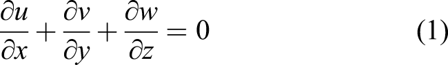
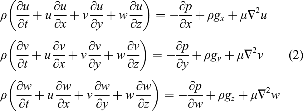
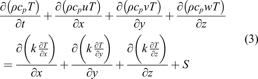
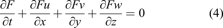
In filling simulation, high-temperature liquid metal flowing is generally regarded as an unsteady flow of viscous incompressible Newton fluid. The turbulent model with k-ε equations is used to solve mass, momentum, energy conservation equations. The volume function method is normally applied to track the changing volume function of fluid surface.
Mass conservation: - u, v, w are velocities in x, y, z directions; g
x, g
y, g
z are gravitational accelerations in x, y, z directions; - ρ is the density; P is the pressure; T is the temperature; μ is the kinematic viscosity; c
p is the specific heat capacity at constant pressure; - F is volume function, and 0 ≤ F ≤ 1.
Several algorithms used in filling simulation are as follows. SIMPLE: the theoretical basis of this method is that the pressure is not directly specified by mass conservation equation. After substituting the pressure into momentum equation, the velocity satisfying mass conservation equation can be obtained. Pressure and velocity are coupled and need to be iterated simultaneously, hence the calculation speed is slow. Based on this method, some researchers proposed improved SIMPLE methods to accelerate iteration speed and reduce calculation time. MAC and SMAC: MAC method was proposed by Harlow and Welch in 1965.
12
This method is based on finite difference grid, two ends of the momentum equation are discretized to obtain Poisson equation for solving pressure field. The continuity equation is used as constraint conditions of the pressure to deform the Poisson equation. The corresponding pressure field and velocity field are solved by iterating the momentum equation and continuity equation at the same time. MAC method adds identification particles to the fluid to track and describe the fluid flow. The characteristic of this method is to solve directly without changing the equations, the velocity boundary conditions are easy to be given. It is suitable for solving viscous incompressible fluid, and it is easy to realize the transformation from two-dimensional to three-dimensional. However, the pressure field and velocity field need to be iterated simultaneously, and lots of tracking particles need to be calculated to accurately reflect the shape of free surface, resulting in large amount of calculation, slow calculation speed and low efficiency. Based on MAC, SMAC algorithm introduces potential function to correct velocity field, which can greatly improve operation speed and save computing memory. SOLA-VOF: the SOLA-VOF method is proposed by Wang in his doctoral thesis in 1985.
13
This method has been the widely used numerical calculation method in casting filling simulation. The momentum equation and continuity equation are solved by SOLA method, and the free surface is calculted by volume of fluid (VOF) method. VOF method defines a volume function F, which is used to represent the volume content of liquid in a fluid unit. When the fluid unit is filled with liquid, F = 1. When the unit has no liquid, F = 0. When 0 < F < 1, the unit has a free surface. By solving the volume fraction F of each fluid element, the position and shape of free surface can be determined. VOF method is verified sufficiently fast and stable to be used in free surface solving problem. With the development of fluid equation from two-dimensional to three-dimensional, the difference scheme and computational grid are more complex and diverse, various improved VOF methods have been proposed and used in various filling numerical simulation software.
The development of computational fluid dynamics for filling simulation is reviewed as follows. In 1983, Hwang and Stoehr 14 first combined computational fluid dynamics with casting filling problem, and simulated the filling flow process of plate casting by two-dimensional method. In 1984, Desai 15 first combined the flow phenomenon and heat transfer in casting filling process. In 1985, Wang 13 applied SOLA-VOF method to casting filling in his doctoral thesis, and verified it with high-speed photography technology. In 1988, Lin and Hwang 16 combined SOLA-VOF method with heat transfer in fluid calculation, considering the computational coupling of flow field and temperature field. In 1991, Jonson et al. 17 simulated the filling results of liquid metal in the cavity under different states, and discussed the influence of liquid metal on the filling results. In 1992, Yeh and Hwang 18 used SOLA-VOF method to solve k-ε turbulence model with free surface. Molten steel flowing is simulated and compared with hydraulic model experiment.
In 1995, Sirrell et al. 19 of the University of Birmingham, UK, published the standard experimental results, which choosed pure aluminum as the experimental alloy, a higher sprue was designed to artificially cause turbulent filling effect, and the change of liquid metal filling state was recorded by X-camera technology. The results showed that most of the calculated filling states with time were similar to experimental results. In 1997, Pan et al. 20 used SOLA-VOF algorithm to analyze gas-liquid flow in filling process, including velocity and bubble flow trajectory, and considered the interaction between gas and liquid. In 1998, at the eighth international conference on Modeling of Casting, Welding and Advanced Solidification Process, Jolly et al. of the University of Birmingham verified the simulation of MAGMAsoft and FLOW-3D software, and given the simulation results of filling the cavity with liquid metal. Hirt et al. of American fluid science company described the calculation model, calculation method and defect prediction model of FLOW-3D software, which was successfully applied in automotive castings. In 1998, Jurgen et al. 21 improved the VOF method. They used unstructured grids to control the unit volume, and converted the hyperbolic equation into a single parabolic equation to reduce the amount of calculation, which has been used in the production of simple castings.
In 1998, Stoehr and Wang 22 improved the SOLF-VOF method and applied it to the three-dimensional filling problem. In 2001, Hong et al. 23 proposed a mathematical model of complex cavity filling process. Schwarze et al. 24 proposed a model for the flow field and dispersed phase behavior in the melt of continuous casting of steel strip. In 2003, Li and Zhou 25 proposed a three-dimensional simulation program for die casting process, and the finite difference method was used to solve three-dimensional N-S equation. In 2004, Mirbagheri et al. 26 proposed an improved SOLA-VOF method to analyze the impact and erosion degree of molten metal on different mold walls. Sakuragi and Takuya 27 proposed a filling process algorithm based on Cold Isostatic Pressing (CIP) and considering surface tension for squeeze casting and die casting process simulation. The simulation results were compared with experimentally measured pore position and size.
In 2005, Kashiwai et al. 28 simulated the vacuum suction casting process of aluminum alloy castings. In 2007, Lee et al. 29 simulated the filling process of semi-solid magnesium alloy, analyzed the rheology and thixotropy of liquid metal at different shear rates and cooling rates, and the effect of viscosity on the filling process. In 2011, Korti et al. 30 simulated aluminum casting filling problem with high pressure. In 2013, Mcbride et al. 31 developed a centrifugal casting model, which can simulate the free surface details of complex centrifugal casting filling process, and verified by hydraulic simulation experiment and high-speed camera.
From the above litteratures, it can be seen that in filling simulation problems, MAC, SMAC and SOLA methods are generally used to calculate N-S and continuity equations, which are used to jointly solve the coupling calculation of pressure and velocity. VOF method is generally applied for free surface treatment. Nowadays, casting filling simulation develops towards specialization and three-dimensional simulation. A specialized subdivision algorithm is developed for casting process of different types and materials. 32,33 At the same time, the development of three-dimensional numerical simulation software is becoming more and more perfect, and many commercial simulation software have been applied in practical production.
Simulation of stress field
The casting thermal stress generated in the solidification process will cause cracks and deformation in the processing and use of castings, which will seriously affect the properties and performance of castings. Therefore, it is necessary to numerically simulate the generation and change of thermal stress.
The numerical simulation of stress field can be roughly divided into two parts, one is the simulation of solid-liquid two-phase region (quasi solid region), and the other is the simulation of the later stage of solidification.
The stress analysis of solid-liquid two-phase region is of great significance to study and predict the casting defects, hot crack, residual stress and residual deformation formed in the solidification zone, because many casting defects such as shrinkage cavity, shrinkage porosity and hot crack are formed at this time. The simulation at this stage generally adopts the rheological model. The rheological model adopts the combination of simple fluid model and ideal mechanical models such as elastomer, viscous body and plastic body to represent the complex flow and deformation law of materials, so as to more accurately reflect the change law of flow and deformation with time. Therefore, the rheological model is more suitable to deal with the flow and deformation law of quasi solid zone during solidification. 34–36
The stress calculation of post solidification stage often uses some mechanical models, 37–40 including the thermoelastic model, the thermoviscoelastic model, the thermoelastoplastic model, the thermoelastic viscoplastic model, the Perzyna model, the Heyn model and the unified variable model.
In the solidification process of castings, stress is closely related to cooling, and uneven temperature distribution will produce thermal stress in castings. Therefore, coupling thermal analysis can improve the accuracy of stress analysis. 41 The mesh generation algorithm of the finite difference method (FDM) is simple, the program design is simple, and the convergence is good. The FDM has unique advantages in predicting the dynamic boundary treatment in the process of shrinkage and porosity. Therefore, FDM is often used in casting simulation of flow field and temperature field. The mesh model of finite element method (FEM) is flexible, which can accurately simulate various complex curved surface or curve boundaries, realize the unified treatment of various boundary conditions, and is suitable for casting simulation of stress field. Therefore, in the coupling simulation of temperature field and stress field, FDM is often used to calculate the flow field and temperature field, and FEM is often applied to calculate the stress field. 42
Simulation of casting microstructure
The macro simulation of filling and solidification has been deeply studied, and many commercial simulation softwares have been widely used and applied in casting production. Numerical simulation of casting alloy microstructure is in the research stage and is a hot spot. 43 In microstructure simulation, the microstructure nucleation and growth model are simulated to reproduce the formation and change process of grain, dendrite, eutectic, component segregation and micro pores. At present, the main numerical methods include deterministic method, stochastic method, phase field (PF) method. Among these methods, Cellular Automaton (CA) method and PF method are the most concerned and studied. Nakajima et al. 44 summarized the computer simulation models of casting filling and solidification process, discussed the development from macroscope-scale model to microscope-scale model, especially the CA model and PF model. Zhang et al. 45 summarized the development of titanium alloy microstructure simulation, including the CA model and PF model.
Deterministic simulation method
In the early stage of solidification microstructure simulation, limited by the development level of computer and macro transmission theory, the deterministic simulation method is mostly used in the microstructure simulation of metal solidification process. At a given time, the nucleation density and growth rate of grains in a certain volume of melt are determined functions. Deterministic simulation is based on volume element to solve the continuity equation. Firstly, the calculation space is divided into volume elements, and the temperature of each volume element is uniform. Then, according to some nucleation laws, the volume element is further divided into micro volume elements, and each micro volume element has a spherical grain growing at a certain speed.
The deterministic method is based on classical solidification kinetics and crystal growth characteristics. The deterministic functions of crystal nucleation density and growth rate in melt are derived, which can describe the changes of nucleation density, dendrite tip radius and growth rate with solidification conditions. Several deterministic models have been proposed by researchers, including the continuous nucleation model, 46 the instantaneous nucleation model, 47 the Gaussian distribution nucleation model, 48 the Rappaz-Theovz nucleation model, 49,50 the dendrite growth model LGK, 51 KTG, 52 the multi-scale multiphase model 53 and the eutectic growth model. 54,55 However, the deterministic method can not consider some random phenomena in the solidification process, such as random nucleation distribution, random crystal orientation, etc., nor can describe the complex microstructure and explain some solidification phenomena, such as the transformation from columnar crystal to equiaxed crystal, the competitive elimination of dendrite growth, the fusing and bifurcation of dendrite arms, etc. In recent years, there are few studies on deterministic models, but its development and improvement have laid the foundation for the subsequent numerical simulation of microstructure.
Stochastic simulation method
The stochastic method uses the probability method to describe the nucleation and growth of grains. There are Monte Carlo (MC) method and CA method, of which CA method is widely used.
MC method divides the calculation element into N micro elements on the grid, and the grain nucleation and growth on each node are calculated according to the probability model. CA method regards the grid element as a cell. The state values of the cell include physical parameters such as temperature, solubility, solid fraction, growth orientation and liquid phase flow rate. At each step, the state values of each cell and the transition of the interface are realized by solving control equations such as temperature and solute field, coupling dendrite growth and capture algorithm.
In 1993, Rappaz and Gandin 56 first used CA method to simulate metal solidification microstructure, and predicted the grain growth and get transformation of Al-Si alloy under different alloy composition and cooling rate. Grandin et al. 57–59 combined the finite element macro heat transfer calculation with CA algorithm to simulate two-dimensional and three-dimensional grain structure of castings under non-uniform temperature field, and applied to simulate three-dimensional grain selection process of directional solidification of superalloys and Al-Si alloys under continuous casting conditions. In 1998, Dilthiy and Pavlik 60 used CA method to simulate the dendrite morphology of alloy. In 1999, Nastac 61 combined the macro temperature field and solid-liquid solute transport equation, solved the interface moving velocity based on the solute conservation equation of interface element, and successfully simulated the growth of free equiaxed and columnar crystals and CET transition in the undercooled melt.
After 2000, the microstructure simulation of solidification process based on CA method has developed rapidly, more factors affecting dendrite growth, such as flow and alloy elements, have been considered, and many improved CA methods have been proposed. 62–66
Phase field (PF) simulation method
PF simulation is also called direct microstructure simulation. It introduces phase field variables to describe complex growth process of the interface between new phase and parent phase and the solid-liquid interface in equilibrium state. It can describe the changements of shape, curvature and movement of solid-liquid interface, and finely describe the transformation of microstructure and the reproduction of complex solidification phenomena, such as coarsening of dendrite arm, fusing and bifurcation. 67,68
The important theoretical phase field model was developed in the 1980s. The early work was dendrite solidification simulation of pure materials and binary materials. Langer 69 and Fix 70 first introduced the phase field model for first-order phase transition. Collins and Levine 71 independently developed a similar diffusion interface solidification model. Langer and Sekerka 72 considered the model of diffusion interface motion in binary alloy system with miscible gap in solid solution phase. Caginalp et al. 73–76 carried out important early works in the development and analysis of solidification phase field model. Penrose and Fife 77,78 provided a framework for deriving phase field equations from a single entropy function in a thermodynamically consistent manner, and the non-isothermal solidification process was modeled. Kobayashi 79,80 carried out pioneering simulation on the growth of two-dimensional and three-dimensional dendritic crystals in the early 1990s, the works proved that the phase field method has the potential for complex microstructure modeling, and promoted the rapid development of phase field calculation in materials science. The combination of phase field and temperature field, flow field, solute field and external action field can truly simulate the macro and microstructure changes in the solidification process. In recent years, the adaptive variable grid and parallel algorithms 81–84 were proposed, and PF method has been greatly improved, showing strong development potential and application prospect, and has become one of the most successful techniques for material microstructure simulation.
Simulation software for casting filling and solidification process
Main numerical simulation software of casting filling and solidification.
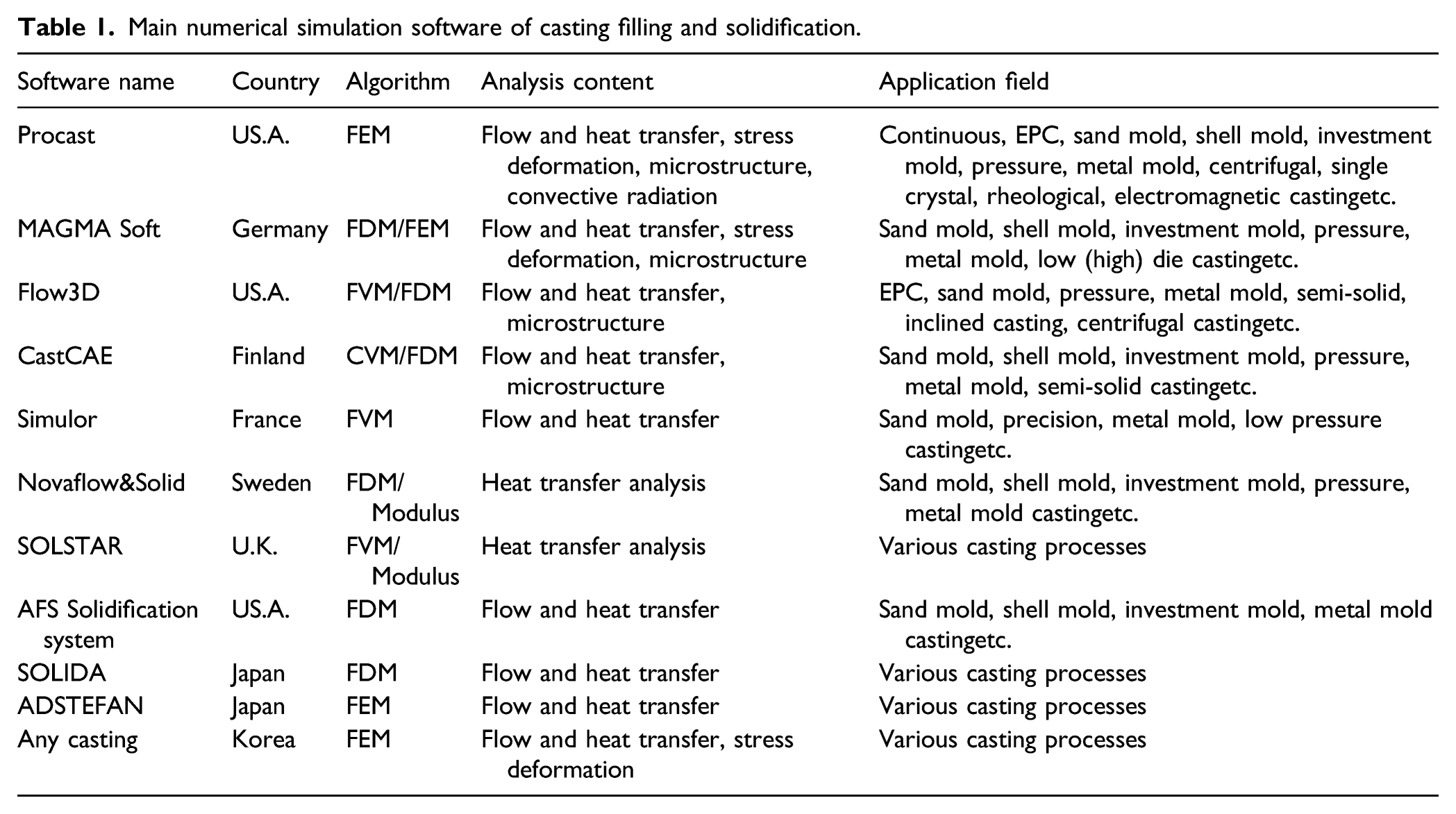
Development direction of current casting simulation software is expanding from low-pressure casting, die casting and investment casting on the one hand, and from macro simulation to microstructure simulation on the other hand. At present, the development direction of numerical simulation is as follows: (1) Oxidation inclusion simulation; (2) Complex multiphase flow simulation; (3) Modeling/core making process simulation; (4) Simulation of pattern generation process of gasified mold casting; (5) Semi solid casting simulation; (6) Microscopic numerical simulation.
Conclusion and perspective
This paper reviews and arranges the research of numerical simulation of casting process in recent years, and discusses and summarizes the solidification process, filling process, stress field, microstructure simulation and the development of commercial software.
At present, the casting simulation technology has been very mature for the macro simulation of shape, size and contour, and the prediction of casting defects. The casting simulation research is developing towards the micro simulation of predicting microstructure, involving crystallization, segregation, diffusion, gas precipitation, and phase transformation and so on. The micro simulation scale even reaches the nanometer level, involving crystal nucleation, crystal growth, dendrite and columnar crystal transformation to metal matrix control. Micro level simulation technologies, such as CA method and phase field method, as well as the combination of micro level and macro level, make the coupling and integration of temperature field, flow field, stress field and microstructure, which makes the current development direction.
Casting numerical simulation technology, also known as “flexible casting technology”, has been used not only in the optimization and prediction of casting design and process parameters, but also further used in the fields of digital manufacturing, virtual manufacturing, intelligent manufacturing.
Footnotes
Declaration of conflicting interests
The author(s) declared no potential conflicts of interest with respect to the research, authorship, and/or publication of this article.
Funding
The author(s) disclosed receipt of the following financial support for the research, authorship, and/or publication of this article: This work is partially supported by the National Natural Science Foundation of China (Grant Nos. U1708253, 61973135, 91948201), and the National Key Research and Development Program of China (Grant No. 2017YFB0702901).