
Abstract
This study investigated the effect of beam oscillation on the solidification behaviour during laser welding of Al-5754 to Al-6061 alloy. In this study, a finite element model has been developed to simulate temperature and fluid flow fields by implementing different combinations of volumetric heat source models. Solidification parameters such as temperature gradient (G), solidification rate (R), cooling rate (G × R) and G/R are evaluated to understand the mechanism of microstructure formation. It was found that beam oscillation improves the tensile strength by 21.4% for full penetration welding due to an increase in the percentage of formation of equiaxed grains. Modelling results revealed that the cooling rate increases with an increase in oscillation frequency. However, tensile strength followed a parabolic distribution with a peak at the oscillation frequency of 300 Hz.
Keywords
Introduction
5xxx/6xxx dissimilar aluminium alloy welding is considered a good strategy to weld the side and back walls for the automotive industry, driven by lightweight manufacturing, combining the advantages of both alloys such as low density, good formability, high strength-to-weight ratio, corrosion resistance, formability and weldability [1]. Remote laser welding (RLW) is an emerging solution to material joining as it offers benefits such as a non-contact welding process, high depth-to-width ratio, less distortion, and remarkable processing efficiency [2]. However, laser welding of Al-alloys poses challenges such as high reflectivity of the laser from the surface and high susceptivity to weld porosity and solidification cracks [3]. 5xxx aluminium alloys are solid solution strengthened by the β(Mg2Al3) phase, having excellent formability and elongation, and are widely used as structural automotive components [4]. 6xxx aluminium alloys are strengthened by Mg2Si precipitates which provide good specific strength and hot crack resistance [5]. Concerning the nature of the RLW process that no filler wire is used, the welding of 5xxx and 6xxx aluminium alloys are considered to be beneficial because it creates weld chemistry that has low crack sensitivity [6].
Investigations on beam oscillation have suggested that it helps to get a stable molten pool and keyhole, improves gap bridging, and leads to the formation of a wider weld seam [7–9]. Most of the studies (details are added in section 1 of the supplementary material) are focused on the effect of beam oscillation on the process stability, gap bridging, porosity, and mechanical properties at lower oscillation frequencies. The effect of the frequency of oscillation is not explored at higher oscillation frequencies. The effect of beam oscillation on mechanical strength is compared with no oscillation welding at the constant heat input whereas the comparison at the similar weld profile (penetration depth) is still missing. However, the impact on grain morphology is not fully understood. This is due to very fast and dynamic solidification behaviour which is difficult to be measured experimentally [10]. The solidification process is affected by the critical interactions between heat transfer and fluid flow behaviour near the solid–liquid interface in the molten pool [11].
This paper aims to investigate the influence of beam oscillation on the solidification behaviour during the laser welding of Al-5754 and Al-6005 in butt joint configuration. A finite element model is developed to simulate the dynamics of heat transfer and fluid flow behaviour during the laser welding process. The solidification behaviour is discussed based on the solidification parameters calculated from the model such as solidification rate (R), thermal gradient (G), and cooling rate (G × R) and its effect on grain morphology and mechanical strength. A detailed comparative study in terms of solidification behaviour, grain morphology, and mechanical strength is carried out for the full penetration welding with and without beam oscillation. The effect of oscillation frequency on the solidification parameters, grain morphology, and mechanical strength is also investigated.
Model description
Numerical model
The numerical study is based on our previously developed laser welding model [12–15] which is described by the solutions of mass, momentum, and energy conservation equations [16]. The difference within this study lies in the definition of the laser heat distribution from the volumetric and hybrid heat sources. Different combinations of hybrid volumetric heat sources are used to represent the spatial distribution of laser energy in the keyhole and for the best prediction of the shape and dimensions of the weld profile. A three-dimensional Cartesian coordinate system is established with the heat source moving along the x-axis as shown in Figure 1(a) and the sinusoidal oscillation in the x–y plane. The following assumptions were made: (i) No gap between the plates is considered; (ii) Boussinesq's approximation [17] is used to account for change of density due to temperature variations; (iii) The weld pool surface is considered flat; (iv) The absorption coefficient of the laser by the workpiece is kept constant as 0.60 [18].
(a) Schematic illustration of geometry and finite element mesh distribution used for the simulations, (b) Weld experiment setup.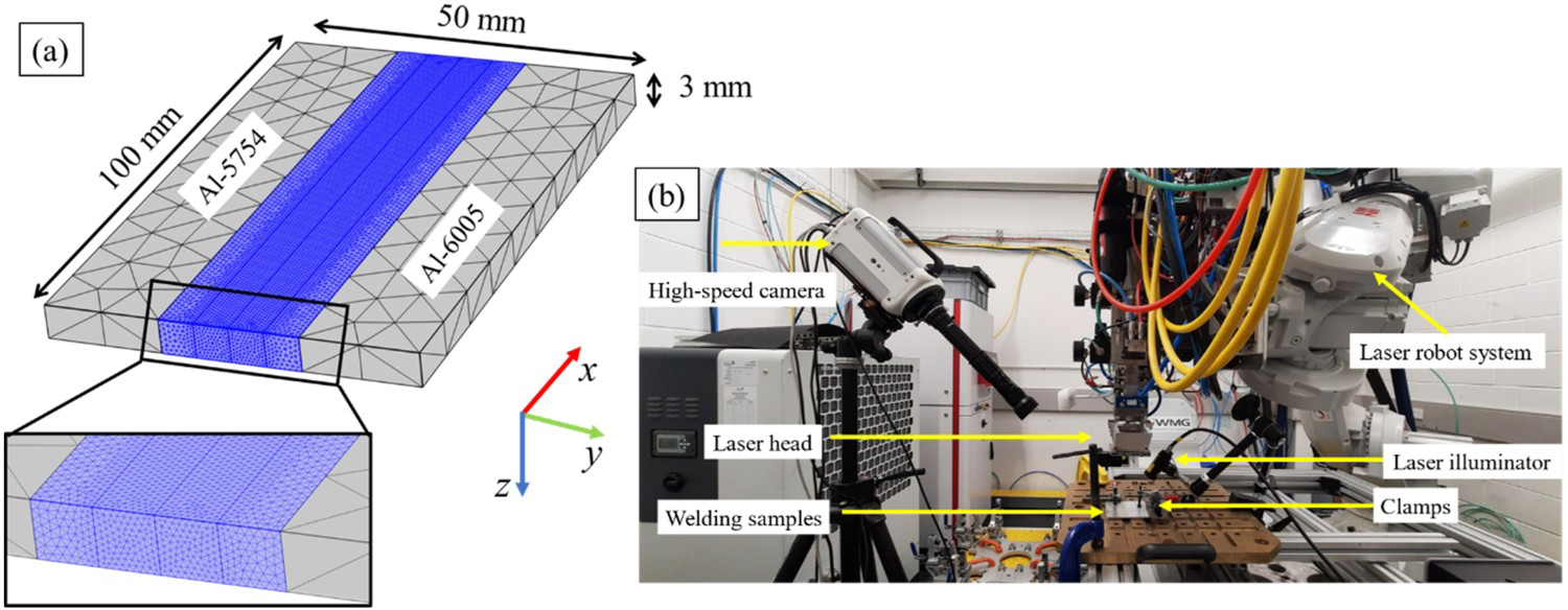
Moving heat input model
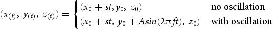
The general trajectory of the moving heat source is given in Equation (1) where s is the welding speed, A is the oscillation amplitude and f is the oscillation frequency.
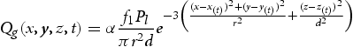
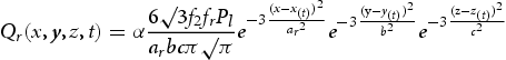
The power density distribution of the different volumetric heat sources with origin (x0,y0,z0) is described as follows:
Case-1 3D volumetric Gaussian heat source [19]
Case-2 3D volumetric Gaussian (Equation (2)) and double ellipsoid heat source combined [20]
Case-3 Gaussian damped heat source and double ellipsoid heat source
where ar, af, b, and c are the heat source distribution parameters depending upon the shape of the weld pool obtained by measuring the rear (ar), front (af), width (b), depth (c) of the half ellipses.
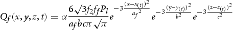

The Gaussian damped heat source model suggested by Yuewei et al [21] was adopted to describe the heat distribution, which is given in Equation (6) as follows:
Case-4 Rotary Gauss body heat source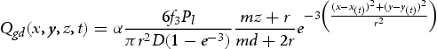

A rotating Gauss body heat source model [22] was used as a volumetric heat source given as:
Case-5 Proposed Modified Gaussian damped heat source and double ellipsoid heat source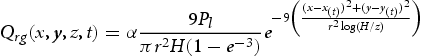
The Gaussian damped heat source is modified to account for the decay of the heat distribution through the thickness of the workpiece in place of specifying it to the depth of penetration. In general, the depth of penetration is provided as input in the model which is calculated experimentally or by interpolation using a surrogate model based on a few experiments. The experimental calculation will not serve the advantages of performing numerical simulations to predict the fusion zone dimensions. Equation (9) is the extension of Equation (6) where the surface heat source is extended to the volumetric heat source. The heat source mentioned in Equation (9) is normalised which gives the integral of Equation (9) as 1. The modified Gaussian damped hybrid heat source eliminates the requirement of providing depth of penetration as an input and is defined as:


The effective heat absorbed by the double ellipsoid and modified Gaussian damped heat source is given by Equation (10). f4 and f2 are the power distribution coefficients (f4 + f2 = 1). Boundary conditions are given in section 2 of the supplementary material.
Numerical implementation
The numerical model is solved using COMSOL Multiphysics 5.6 software. The algebraic multigrid solver was adopted as it provides robust solutions for large CFD simulations. The discretisation in space is done using the finite element method and time discretisation is done using the backwards differential formula. The system is solved fully coupled and the damped Newton method is used for solving systems of non-linear equations. The size of the simulation domain for a single plate is 100 mm × 25 mm × 3 mm with each plate divided into three domains to improve the mesh distribution as shown in Figure 1(a). Tetragonal mesh is used with a minimum mesh size of r/8 mm having a total number of mesh elements of 750,639 elements. The temperature-dependent material properties of AA-5754 and AA-6005 alloys are taken from [23,24] and COMSOL material library [25]. These properties are defined locally using a piecewise function and in case of unavailability of material properties beyond a certain temperature, the values are taken as constant for the last known temperature.
Experimental methods
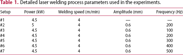
Detailed laser welding process parameters used in the experiments.
The welded samples were sectioned normally to the welding direction and polished to a surface finish of 0.05 µm, followed by etching in caustic sodium fluoride reagent (2%NaOH + 5%NaF + 93% water). The weld dimensions were measured in a Keyence VHX7000 optical microscope. EBSD mapping was conducted on a JEOL 7800F scanning electron microscope. Grain size is determined by the equivalent diameter of the circle for equiaxed grain and fitted ellipse major diameter for columnar grains using AztecCrystal software. The mechanical properties of the joints are assessed using a uniaxial tensile test performed using a 30 kN static Instron Universal tensile machine according to ASTM-E8 using a sub-sized tensile specimen [26]. To check the repeatability of each welding condition, three weld seams are prepared for each weld setup and five tensile test samples were prepared from each weld seam.
Results and discussions
The process parameters combinations used for welding trials are given in Table 1 and corresponding experimental values for the weld width and weld depth obtained using optical microscopy and calculated values from the model are given in Figure 2.
(a) Variation of surface power density with the volume power density for #1 and #2, and simulated weld cross-sections for all 5 volumetric heat sources for setup #1. (b) optical micrograph of the welded region, (c) comparison between experimental and simulated weld width, and (d) penetration depth.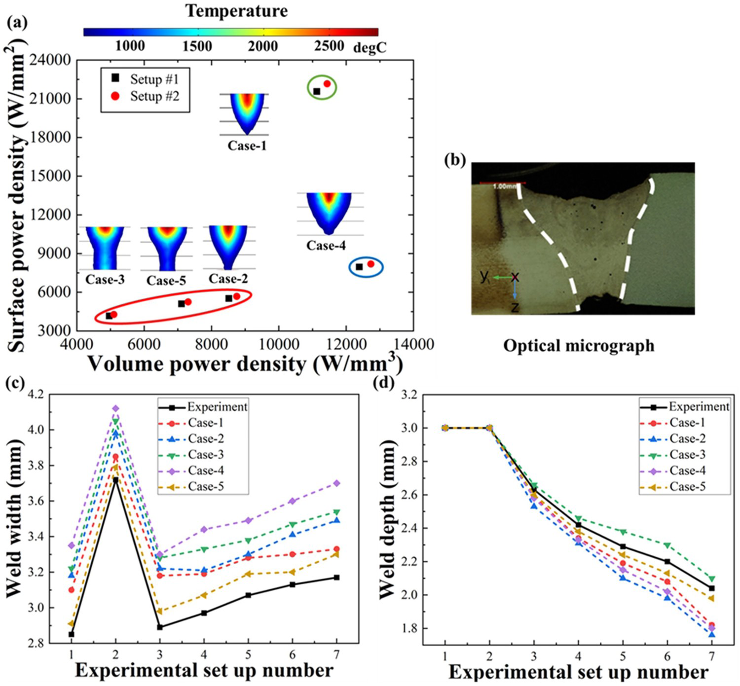
Model validation
The numerical model is validated by comparing the weld cross-sections and morphologies of the top surface of the weld pool with the corresponding experimental results. It is required to estimate the similarities between the different heat sources based on the heat distribution such that the most appropriate heat sources can be identified. Also, this will showcase the position of the new heat source based on different distribution functions. The volumetric heat source model is the simplified approach to model keyholes as it quantifies the heat input and distribution through the complex keyhole formation. The shape of the weld profile depends on the heat distribution along the surface and the volume of the workpiece. This heat distribution is governed by the power densities at the surface and inside the volume of the workpiece. Figure 2(a) shows the variation of surface power density with volume power density for all 5 volumetric heat sources for setups #1 and #2. Figure 2(a) represents the shape of the weld cross-section predicted from the numerical model for all heat sources based on the temperature distribution. It was found that the heat sources for cases 2, 3 and 5 can be combined based on the similarity of the surface and volume power densities. Case-1 has the highest surface power density of all the cases which suggests that it has the highest peak temperature in all cases. Case-4 has the highest volume power density which suggests that it has the highest heated volume which can be seen from the temperature distribution for the weld profile. The heat distribution developed by case 4 is different from the rest. Figure 2(b) shows the optical micrograph of the weld cross-section obtained for setup #1. It is evident from Figure 2(a–b) that the shape of the weld cross-section predicted in case 5 has the best agreement with the experimental observation. Figure 2(c–d) summarises the weld width and depth of penetration obtained from the experiments and the numerical models for all the experimental setups performed in this work for all volumetric heat sources. The average percentage error of different volumetric heat source models is 6.7% (case-1), 9.2% (case-2), 9.5% (case-3), 10.1% (case-4), and 2.1% (case-5) as given in Figure 2(c–d). Case-5 has the lowest error of 2.1% of all as shown in Figure 2(c–d) for all the experimental setups.
The second comparison is based on the weld pool morphologies of the top surface. Case-5 is used for the development of weld pool morphology at the top surface as it generates the best results based on the shape and dimensions of the weld cross-section. The experimental high-speed camera images of the top surface of the weld pool for no oscillation and beam oscillation welding are shown in Figures 3(a–b) respectively. Figure 3(c–d) shows the simulated weld pool morphologies which are indicated by isothermal contours from liquidus temperature to boiling point. The keyhole profile is roughly circular (Figure 3(a–b)) which matches the simulated contour map (Figure 3(c–d)). The comparison of the length of the weld pool and width of the weld pool between the experiment and simulation are in good agreement with an overall 4.95% difference, demonstrating the validity of the employed model.
Comparison of the weld pool top surface morphologies between the experimental high-speed camera (a and b) and numerical simulation, including the absolute temperature profile (c and d) for different setups. The temperature above the boiling point where the keyhole is formed is shown in white colour in the contour map.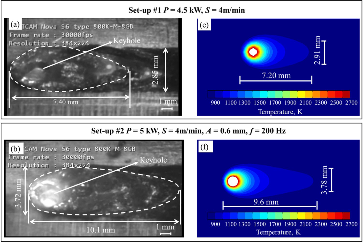
Influence of beam oscillation on grain morphology during full penetration
The simulated temperature (weld thermal cycles are represented in Figure S.1 in section 3 of the supplementary material), flow fields, and solidification process are combined to investigate the effect of beam oscillation on grain morphology. The evolution of the solidification behaviour of the top surface at the solid–liquid interface is demonstrated by studying the solidification parameters. It has been proposed that the grain structure of a weld depends on the solidification rate (R) and temperature gradient (G) during solidification [18,27]. The ratio G/R is proportional to the morphology of solidification and G × R is proportional to the size of the grains formed [28]. The threshold value for G/R is 7 × 10³ Ks/mm for the dendritic structure of the aluminium alloys and a lower value of G/R promotes equiaxed dendritic structure [18,29]. Figure 4 compares the variation of solidification parameters (G, R, G × R, and G/R) along the representative isotherm (898 K) on the top surface of the molten pool boundary. In both no oscillation and beam oscillation cases, G exhibits uniform distribution at the weld centre and increases rapidly along the fusion boundary and beam oscillation conditions have a lower temperature gradient as shown in Figure 4(a). The solidification rate decreases from the weld centre to the fusion boundary and a relatively high peak is found for the no oscillation condition as shown in Figure 4(b). The G × R follows a peak shape with a peak value at the weld centre suggesting that the refined grains are formed at the weld centre and grain growth occurs towards the fusion boundary. The no oscillation condition has higher G × R, which suggests that the grain size will be smaller as compared to the beam oscillation condition. The G/R value for both cases is below the critical value for the formation of cellular or dendritic microstructure, therefore, a dendritic microstructure is expected in the fusion zone. The G/R follows a ‘U’ shaped distribution with a minimum value located at the weld centre suggesting that the equiaxed grains form at the weld centre [28]. The lower value of G/R for beam oscillation conditions demonstrates the formation of more equiaxed grains. The shape of G × R is similar to R and the shape of G/R is similar to G. The solidification parameters also suggest that there is the formation of a larger fusion zone for beam oscillation condition as compared to no oscillation condition. This can be attributed to the larger width of the solidified region at the top surface as shown in Figure 4.
Comparison of the solidification parameters for welds produced with no oscillation and beam oscillation during full penetration, extracted from the solidification isotherm on the top surface: (a) thermal gradient, (b) solidification rate, (c) G × R and (d) G/R.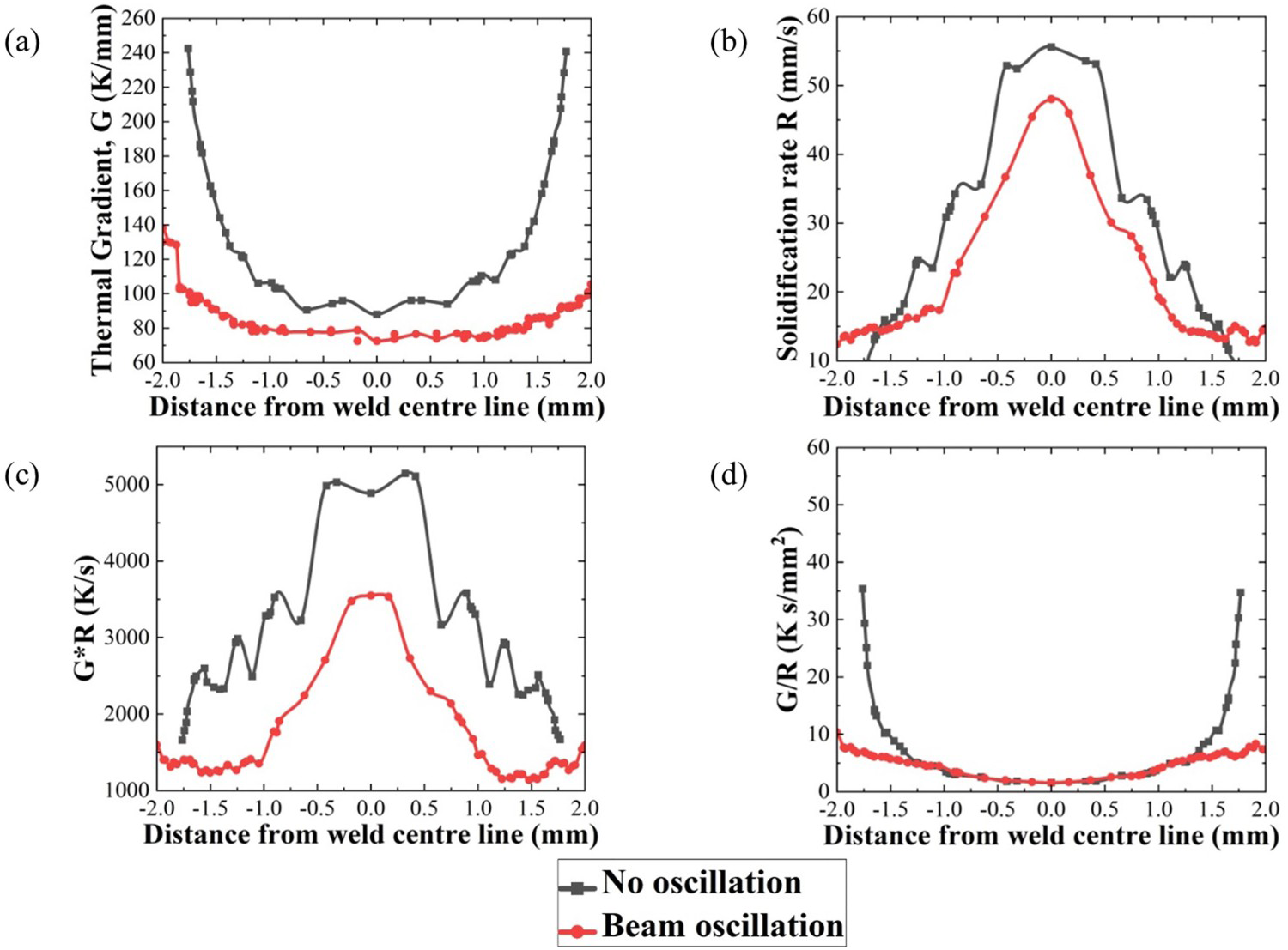
EBSD analysis was performed across the transverse cross-section of the weld zone to investigate the impact of beam oscillation on the weld microstructure and to compare the findings obtained from the numerical model. The grain structure maps for both oscillation and no oscillation conditions are shown in Figure 5. The weld cross-sections are comprised of equiaxed grains marked as fusion zone 1 (FZ1) at the centre and columnar grains marked as fusion zone 3 (FZ3) at the boundary of the fusion line. The columnar grain morphology is typical for dendritic growth, which is in the direction of the thermal gradient. It is evident that the fusion zone region and the region of equiaxed grains both increase with beam oscillation. An increase in the equiaxed region in the fusion zone, which is evident from the ratio of equiaxed area to total fusion zone area, increases the isotropy of the weld preventing crack propagation during the tensile test [30] and reducing crack susceptibility [29]. Consequently, an increase in tensile strength by 21.4% is determined with the application of beam oscillation (Figure 5(c)). The average grain size of the equiaxed and columnar region is smaller for no oscillation conditions which are well correlated to the region with the highest cooling rate values, following the same trend as in the numerical model. The beam oscillation condition has a larger region of equiaxed grains which is correlated to the lower G/R value, which again is consistent with results from the numerical model.
EBSD IPF maps showing the grain structures for (a) setup #1, (b) setup #2, and (c) provide the grain size, area of a different region, and tensile strength.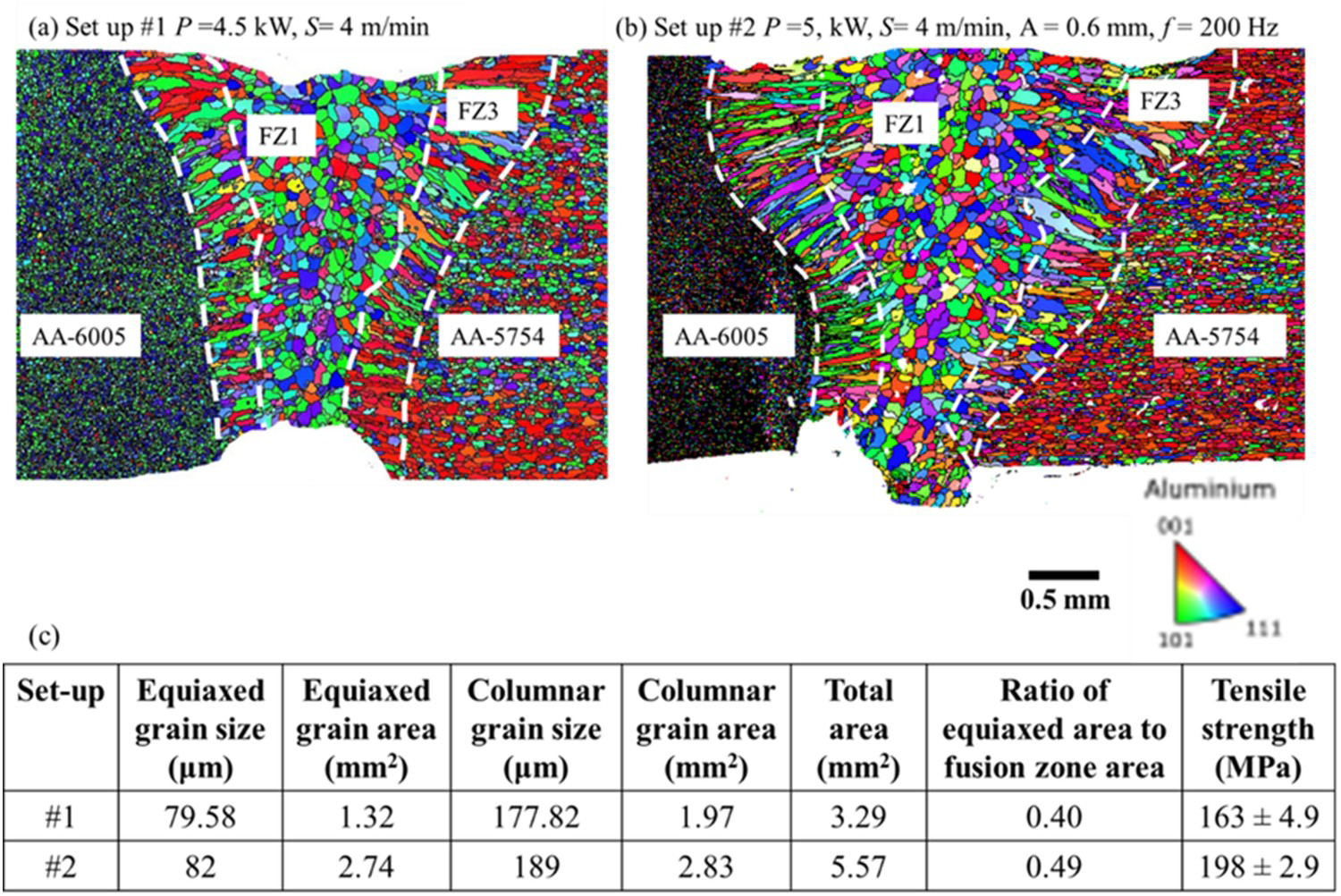
Influence of frequency of oscillation on grain morphology
To investigate the influence of the frequency of oscillation on the evolution of solidification behaviour, solidification parameters are studied along the top surface of the molten weld pool boundary. Figure 6 shows the solidification parameters for different oscillation frequencies for setups #37 (weld thermal cycles are represented in Figure S.1 in section 3 of the supplementary material). The G demonstrates uniform distribution at the centre and increases along the fusion boundary (see Figure 6(a)). The G value remains constant with an increase in oscillation frequency. The R increases with an increase in oscillation frequency. This is due to an increase in the travel speed of the laser beam with increasing oscillation frequency which increases the R. The G × R has a peak shape which shows that the fine grains will form at the centre and coarse grain growth around the boundary of the fusion zone. The peak of G × R increases with an increase in oscillation frequency suggesting that the smallest grains will be formed at the highest oscillation frequency. It is also worth noting that the peak broadens with the increase in oscillation frequency, suggesting that grain growth is hindered and more regions of finer grains will be formed. The G/R is below the threshold value of 7 × 10³ Ks/mm for the dendritic structure [18,29] and a lower G/R value at the centre suggests the formation of equiaxed grains as shown in Figure 6(d). Slight differences in the value of G/R were observed among the welds with varying frequencies. Overall, the solidification parameters suggest that an increase in oscillation frequency leads to the formation of finer grains and hinders grain growth at a higher frequency.
Solidification parameters for welds produced with varying oscillation frequencies from 100 Hz to 500 Hz, extracted from the solidification isotherm on the top surface: (a) thermal gradient, (b) solidification rate, (c) G × R and (d) G/R.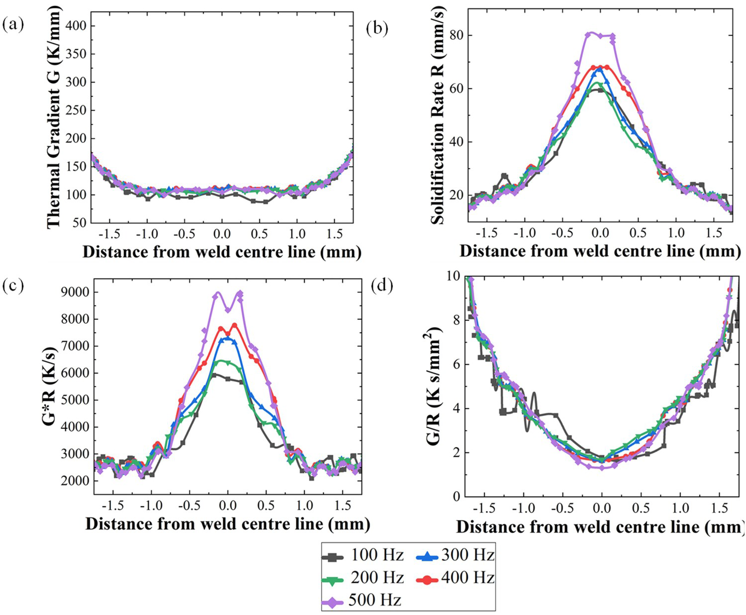
EBSD analysis was performed to investigate the influence of oscillation frequency on weld microstructure and to validate the findings observed from the numerical model. The weld profile looks asymmetrical in the EBSD maps due to the gaps between the plates and difference in the grain morphology of the base metals which leads to asymmetricity in the EBSD results. However, there is slight asymmetricity reflected in the maps of solidification parameters. The grain structure maps for different oscillation frequencies are shown in Figure 7(a–e). The weld cross-sections are comprised of three distinguishable zones: equiaxed grains (FZ1), broken columnar grains (FZ2), and long columnar grains (FZ3). The presence of broken columnar grains (FZ2) is due to stirring action in the weld pool which disturbs the growth of the columnar grains in the mushy zone and promotes finer grains [30]. This disturbance breaks the growth of the columnar dendrites in the mushy region and promotes the formation of fine columnar grains [30] which is consistent with the findings obtained from the numerical model. With increasing oscillation frequency, the fusion zone dimension decreases, which is evident from Figure 7(f). This is due to the decrease in line energy with the increase in oscillation frequency. With the increase in oscillation frequency, it was found that the grain size gradually decreases (see Figure 7(f)). It is evident from EBSD maps (Figure 7) that an increasing oscillation frequency increases the size of the FZ2 which is confirmed by the increase in the ratio of the area of FZ2 to the total area of the columnar zone. This is due to the increase in stirring by the oscillating beam which can be correlated to the broadening of the peak of G × R from the numerical model. It should be noted that the ratio of areas is provided in place of absolute value as the fusion zone area is not constant for all the cases and the ratio is a more critical parameter for the comparison. The tensile strength (given in Figure 7(f)) decreases with the increase in oscillation frequency to 300 Hz and then again decreases with increasing frequency. The increase in tensile strength is due to the decrease in grain size of both the equiaxed and columnar regions but the decrease in the tensile strength with an increasing frequency above 300 Hz is due to the decrease in the percentage of equiaxed grains formed which is demonstrated as the ratio of equiaxed area to fusion zone area reported in Figure 7(e). The decrease in percentage of equiaxed grains leads to a decrease in grain boundaries which acts as a barrier for crack propagation and thus makes the weld susceptible to cracking [29,30]. In all cases, the fracture occurs close to the Al-6005 boundary.
EBSD IPF maps showing the grain structures for varying oscillation frequencies of (a) 100 Hz, (b) 200 Hz, (c) 300 Hz, (d) 400 Hz (e) 500 Hz, and (f) provide the grain size, area of a different region, and tensile strength.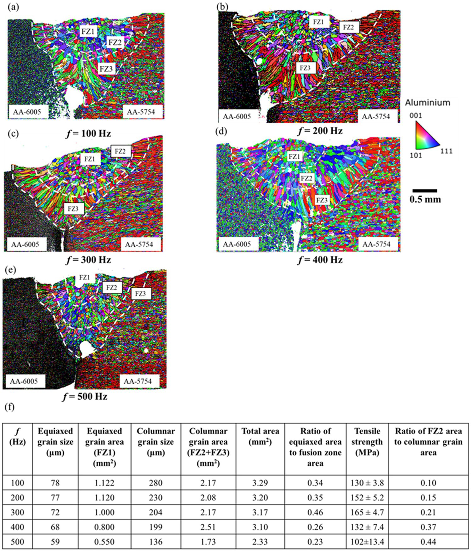
Conclusions
This paper studied the impact of beam oscillation on the solidification behaviour, grain morphology, and mechanical performance of laser-welded Al5754-Al6005 alloy. The main findings are as follows:
There is a good agreement between the simulations and obtained experimental results of weld profile, weld width, and depth of penetration with an overall error of 4.9%. The mapping of the different combinations of hybrid heat sources based on the surface and volume power densities provides the basis for the selection of the most appropriate volumetric heat source models. This opens an interesting future opportunity in the area of laser beam shaping as a tool to select the most appropriate heat source models to simulate the dynamics of laser beam shaping.
The G × R follows a peak-shape distribution with a peak value at the weld centre suggesting that the refined grains are formed at the weld centre and grain growth occurs towards the fusion boundary. For full penetration welding, the higher peak value of G × R for no oscillation condition suggests finer grain formation as compared to beam oscillation condition which is well correlated to EBSD analysis due to the higher cooling rate (G × R) value. During full penetration welding, tensile strength increases by 21.4% with beam oscillation. This is due to an increase in the percentage of equiaxed grains formed along the tensile direction which hinders crack propagation.
The R and the peak of G × R increase with an increase in oscillation frequency suggesting that the smallest grain will be formed at the highest oscillation frequency. The broadening of the peak with increasing oscillation frequency suggests that grain growth is hindered, and more regions of finer grains will be formed. High oscillation frequency results in high solidification and the cooling rate allows a finer grain formation but an area of equiaxed grain decreases. While low oscillation frequency results in lower cooling rate results in coarser grain and a higher area of the equiaxed grain. Results showed that a compromised solution which balances wider equiaxed grains formation and better grain refinement was determined at an oscillation frequency of 300 Hz having maximum tensile strength.
Footnotes
Disclosure statement
No potential conflict of interest was reported by the author(s).