
Abstract
Commercial laser interferometers are conventionally used to measure the positioning error of a long linear stage in multiaxis computer numerical control machine tools. However, commercial laser interferometers are costly and difficult to use. Therefore, a low-cost photodetector-based heterodyne interferometer combined with an electronic phasemeter module was proposed for precise measurement of the positioning error of a long linear stage. The proposed heterodyne interferometer was combined with a virtual electronic phasemeter that employs a self-developed signal-processing technique. Our core algorithm and proposed photoelectric-signal-processing technique were developed using the LabVIEW human–machine interface. Moreover, to verify the performance of the proposed heterodyne interferometer, a laboratory-built prototype was constructed and used to measure the positioning error of a long linear stage. The experimental results indicated that the positioning accuracy of the proposed interferometer was ±4.5 μm for a linear stage with a displacement of 250 mm; the results obtained were comparable to those obtained with a commercially available laser interferometer. The proposed heterodyne interferometer can thus be used in other applications related to precision engineering.
Keywords
Introduction
Multiaxis computer numerical control (CNC) machine tools such as three-axis and five-axis CNC machine tools are increasingly being used in precision engineering. 1,2 A linear stage is an essential component of multiaxis CNC machine tools; a linear stage is used to guide an object along a single translational axis. Ideally, a linear stage has a single degree of freedom (DOF) when it moves along a straight line; however, a linear stage exhibits 6-DOF motion when it moves. Therefore, a linear stage has 6-DOF geometric errors: positioning error, horizontal straightness error, vertical straightness error, pitch error, yaw error, and roll error. 3,4 The motion characteristics of the linear stage have a considerable impact on the quality of the finished machined product and the machining accuracy. 5 Hence, if the 6-DOF geometric errors of the linear stage in multiaxis CNC machine tools can be measured and compensated for, the quality of the machined product and accuracy in machining can be increased. 6–9 Conventionally, laser interferometers (for example, the Renishaw XL-80) are used to measure the geometric errors of a linear stage. However, laser interferometers are expensive, and they can only measure a 1-DOF geometric error of the linear stage in an experimental setup. Therefore, their measurement efficiency is low. 3,10 To address these shortcomings, numerous systems for simultaneously measuring the 6-DOF geometric errors of the linear stage of multiaxis CNC machine tools have been developed in recent years. 1–9,11–17 These measurement systems can be broadly classified as systems using (1) noninterferometric optical sensing technologies and (2) interferometric technologies. Noninterferometric optical sensing technologies have been demonstrated to have various advantages, including small size, low cost, and high accuracy; moreover, they enable noncontact measurement. 1,2,5,9
In a previous study, the present group developed a novel and easy-to-implement system with a simply structure for simultaneously measuring the 6-DOF geometric errors of a linear stage. This system was based primarily on the principles of geometrical optics; therefore, it is inexpensive and highly accurate. 3 However, the system cannot be used for measuring the geometric errors of a long linear stage with a traveling range of >200 mm. Owing to the inherent limitations in geometrical optics, measuring the positioning error with high precision and accuracy for such long traveling ranges is challenging. Therefore, the precision and accuracy of our developed measurement system must be increased to enable measurement of the positioning error of a long linear stage.
In another previous study, the present group developed a novel precise and simple system for simultaneously measuring 6-DOF geometric errors of a long linear stage. The developed measurement system combines interferometric and geometrical optics technologies. In this system, a commercial laser interferometer (Renishaw XL-80) is employed to measure the positioning error of a long linear stage with a traveling range of >200 mm. 1 However, the manufacturing cost of this system is high because commercial laser interferometers are expensive. Therefore, lowering the manufacturing cost of the developed measurement system is imperative.
Heterodyne interferometers have been widely used in various applications such as displacement and angle measurements owing to their high signal-to-noise ratio, wide dynamic range, and direct traceability to the length standard. 18–20 Hence, in this paper, an inexpensive heterodyne interferometer based on a virtual electronic phasemeter is proposed for measuring the positioning error of a long linear stage. In the proposed approach, a virtual electronic phasemeter is used to replace the conventional electronic phasemeter through the application of a self-developed photoelectric-signal-processing technique. The proposed photoelectric-signal-processing technique is implemented using only the LabVIEW (Laboratory Virtual Instrumentation Engineering Workbench) human–machine interface (HMI) and a self-developed algorithm. The proposed heterodyne interferometer is cheaper than the aforementioned commercial laser interferometer. For measuring the positioning error of the linear axis, the total volume of the optoelectric mechanical system is large; this size helps to account for spatial interference and to achieve high-precision analysis. However, achieving high measuring accuracy in the frequency domain is costly and typically dependent on a special and expensive high-resolution circuit device.
The remainder of this paper is organized as follows. In Section 2, the structure and measurement principle of the proposed heterodyne interferometer is introduced. In Section 3, the proposed virtual electronic phasemeter is described. In Section 4, the experimental characterization of the proposed heterodyne interferometer using a laboratory-built prototype is discussed. Finally, in Section 5, some brief concluding remarks are presented.
Proposed heterodyne interferometer with a virtual electronic phasemeter
Structure of the proposed heterodyne interferometer
This study focused on the use of the proposed heterodyne interferometer to resolve the aforementioned problem; a self-developed photoelectric-signal-processing technique and the LabVIEW core algorithm were used to calculate the displacement distance of the linear axis. Figure 1 displays the structure of the proposed heterodyne interferometer based on a virtual electronic phasemeter for measuring the positioning error of a long linear stage. In our proposed interferometer, an electro-optic modulator (EOM)—in which a signal-controlled element exhibiting an electro-optic effect is used—is adopted to modulate a beam of light (Figure 1). The modulation may be imposed on the phase, frequency, amplitude, or polarization of the beam. The heterodyne light sources (two frequencies, namely f
1 and f
2) traditionally consist of a He–Ne laser light source and an electro-optic frequency shifter. Here, the traditional method of building heterodyne sources is not used because a virtual electronic phasemeter was adopted to ensure low-cost application. Therefore, our laboratory-built prototype directly used an oscillator to produce periodic signal voltages with a sawtooth waveform and to drive an EOM. The light beams (f
1 and f
2) passed through a beam splitter (BS), where they were split into distinct light beams (a reference light beam and a measurement light beam). Structure of proposed heterodyne interferometer.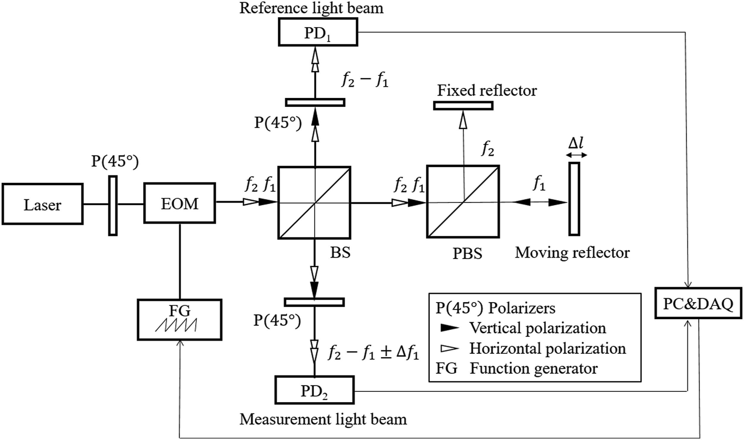
The light beams (f 1 and f 2) of the reference light beam are passed through a quarter-wave plate (P) and incident on a photoelectric detector (PD1). A heterodyne interference signal is thus generated in PD1. The light beams (f 1 and f 2) of the measurement light beam are passed through a polarized BS (PBS), where they are further split into two separate light beams (two frequencies of f 1 and f 2). The first subseparate light beam (f 2) is incident on a fixed reflector surface. The light beam reflected from the fixed reflector surface passes back through the PBS, the BS, and another P, after which it is finally incident on another photoelectric detector (PD2). The second subseparate light beam (f 1) is incident on a moving reflector surface. The moving reflector is set up on the long linear stage. The light beam reflected from the moving reflector surface passes back through the PBS, the BS, and the P, after which it is finally incident on PD2. The first and second subseparate light beams generate another different heterodyne interference signal on PD2.
These two heterodyne interference signals on the photoelectric detectors are then analyzed using the proposed virtual electronic phasemeter developed to measure the positioning error of a long linear stage (see Section 3). The proposed virtual electronic phasemeter, which employs a self-developed photoelectric-signal-processing technique, is used instead of the conventional electronic phasemeter to reduce the manufacturing cost. The proposed photoelectric signal processing is implemented using only the LabVIEW HMI and self-developed algorithm. Figure 1 presents the structure of the proposed heterodyne interferometer, which is composed of a laser light source, an EOM device, two photodetectors, a BS, a PBS, and three polarizers. The core algorithm accompanied by a self-designed sawtooth wave function generator circuit was used instead of employing a common configuration for commercially available heterodynes, which often includes a lock-in amplifier, a somewhat expensive device, and a Mach–Zehnder interferometer configuration. A major aim was to minimize the total manufacturing cost of the proposed heterodyne interferometer.
Measurement principle
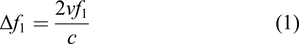
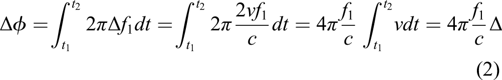
In this section, the measurement principle of the proposed heterodyne interferometer is described. During measurement of the position error of a long linear stage, the moving reflector moves at a constant velocity v. As indicated in Figure 1, the motion of the moving reflector stretches the reflected light beam (frequency f
1 and wavelength
Because the optical path difference between the reference and measurement light beams can be altered at any time during the measurement of the geometric errors of the long linear stage, the heterodyne interference signal on PD2 can also be altered at any time. According to interference theory, the number of shifts in the heterodyne interference fringes N on the two photoelectric detectors can be obtained as
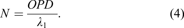
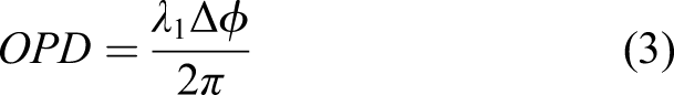
Equation (4) indicates that the optical path difference between the reference and measurement light beams can be obtained by determining the number of shifts in the heterodyne interference fringes N on the two photoelectric detectors by using the proposed virtual electronic phasemeter. Subsequently, by substituting OPD into equations (2) and (3), the displacement
Proposed virtual electronic phasemeter
The method used to process the signals from the heterodyne interferometer is key to realizing high-precision measurement over a large range. 18 Electronic phasemeters or lock-in amplifiers are conventionally used to analyze and process the heterodyne interference signals. 22–27 However, these devices are expensive and difficult to use. Therefore, in this study, a self-developed photoelectric-signal-processing technique was employed for processing the signals of the heterodyne interferometer on the basis of a virtual electronic phasemeter; moreover, to reduce the manufacturing cost, the proposed heterodyne interferometer was used instead of a conventional electronic phasemeter for measuring the positioning error of a long linear stage. The proposed photoelectric-signal-processing technique is implemented using only the LabVIEW HMI and a self-developed algorithm.
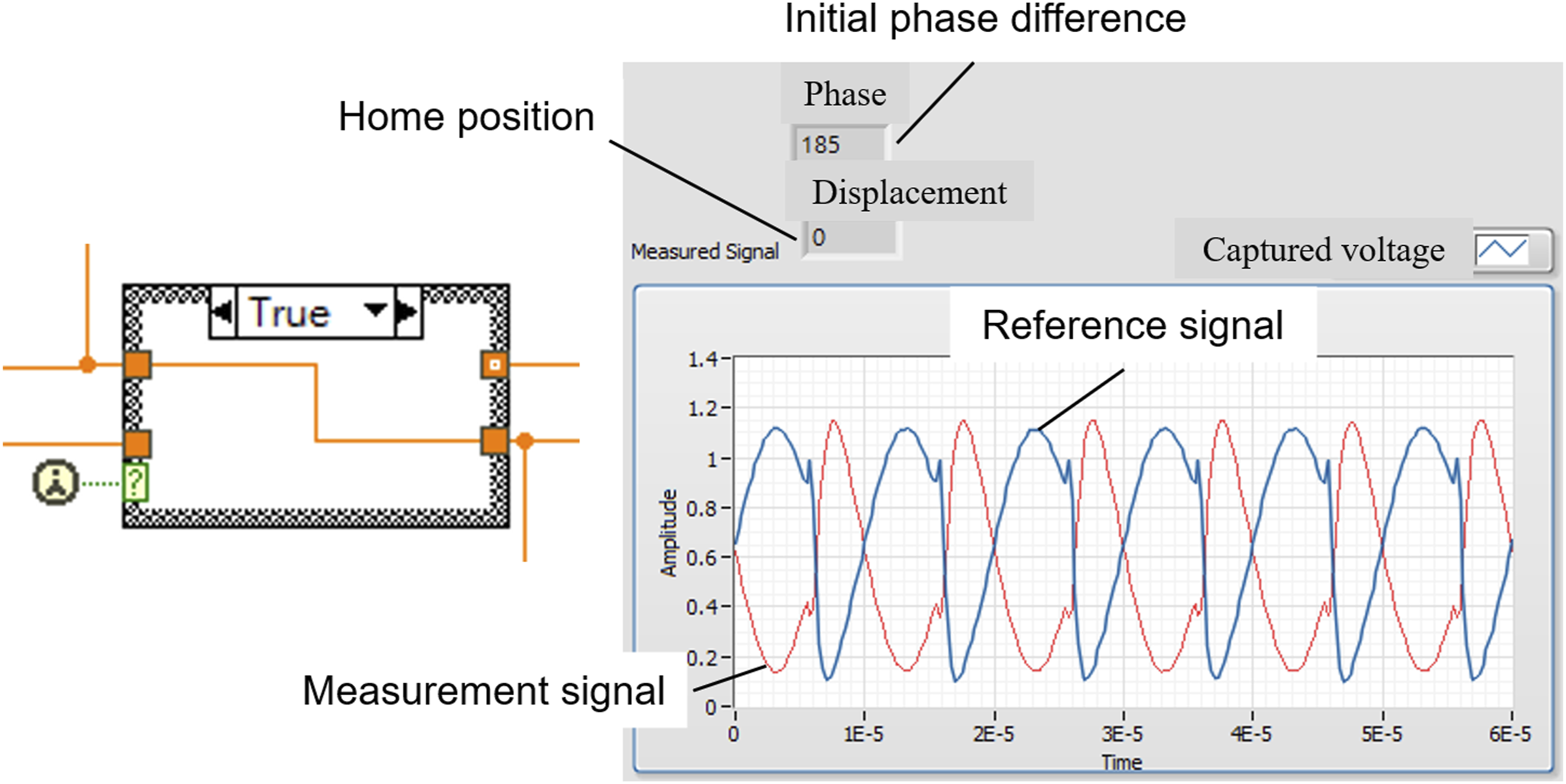
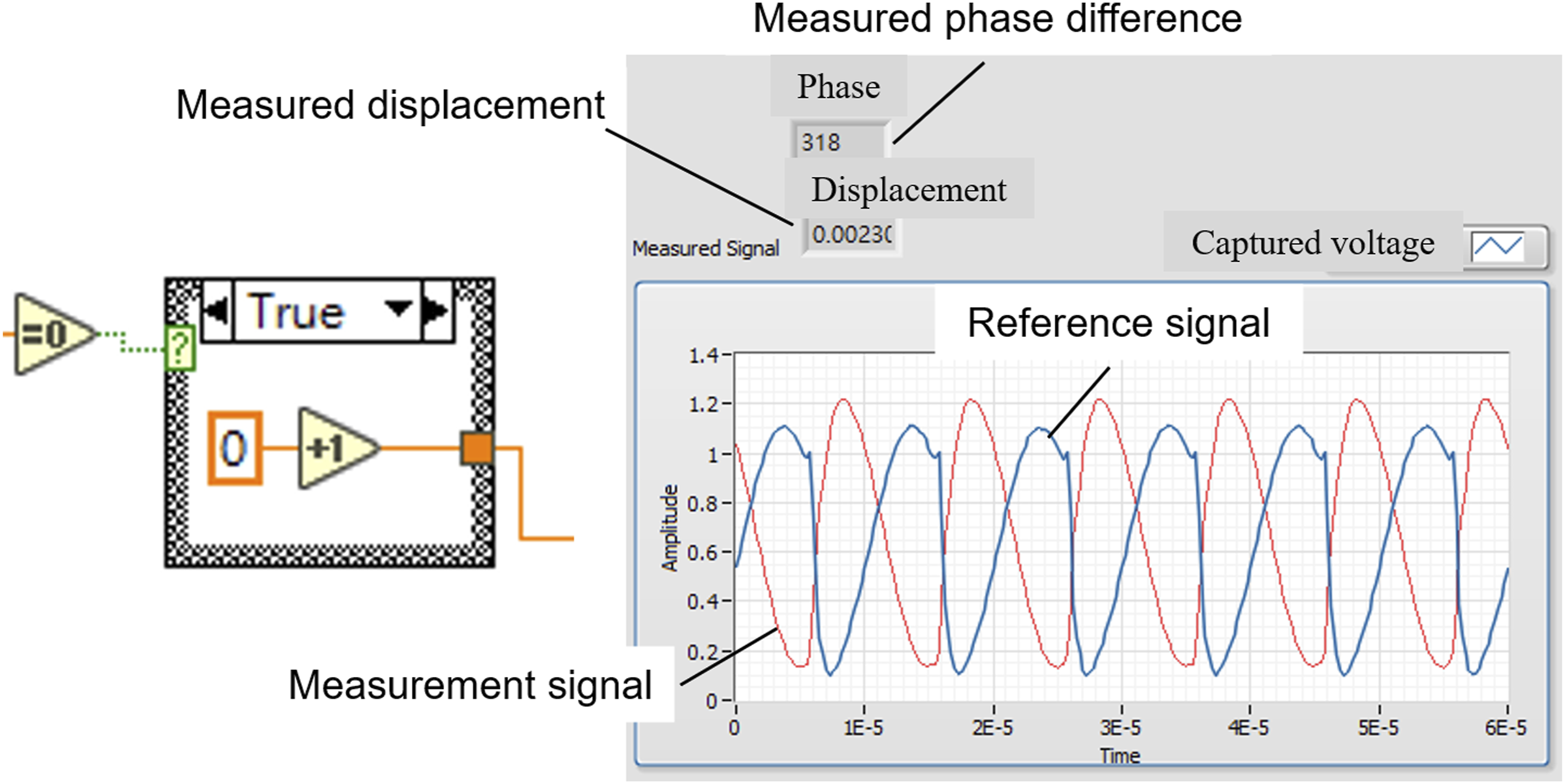
The key part of the proposed virtual electronic phasemeter is the considerable focus on high-resolution phase wrapping. In the traditional method, the conventional electronic phasemeter is commonly used to resolve phase wrapping. However, the proposed heterodyne interferometer is implemented using the LabVIEW HMI (Figure 2) and a proposed algorithm. The LabVIEW implementation includes the following four steps: First, a periodic electric voltage pulse is used to trigger the generation of a heterodyne light source through the LabVIEW HMI. Second, in the proposed heterodyne interferometer, two PDs are used to calculate and retrieve the initial phase between the reference and sample light beams; thereafter, the initial phase value is adjusted to 0°. Third, in accordance with interference theory, the phasemeter indicates the relation between the phase variation and displacement by counting the interference pattern number, which is often compared with the half-wavelength of the light source. The first call function is used to process the signals and store the data in combination with the case structure function in LabVIEW (Figure 3). Fourth, the virtual electronic phasemeter determines the accumulated fringe pattern number by using the shift register, thus obtaining more information on the exact displacement while the platform is moving. Proposed LabVIEW HMI. Home position and initial phase difference.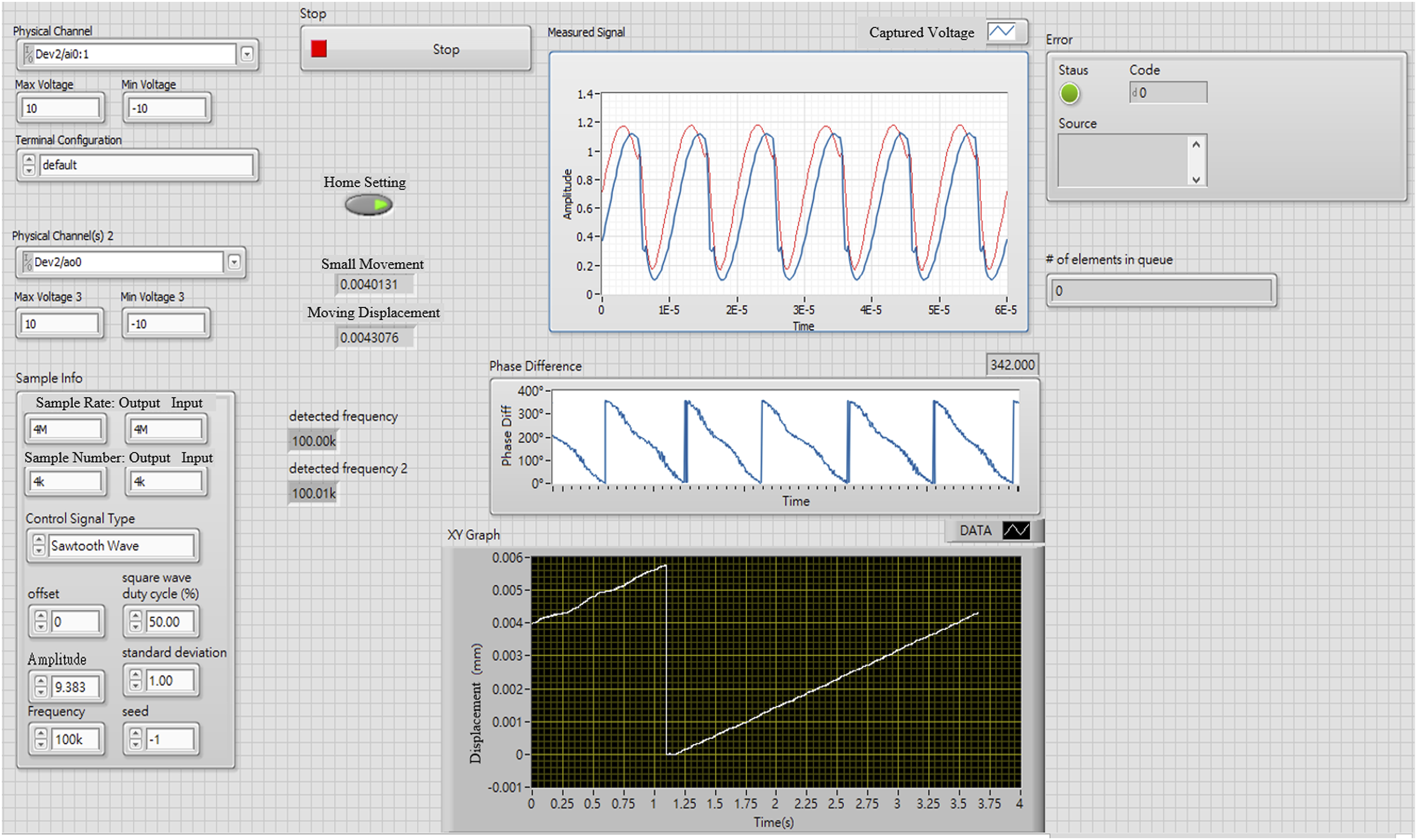
Subsequently, when the long linear stage is moved, the number of shifts in the heterodyne interference fringes N on the two photoelectric detectors is measured using the proposed virtual electronic phasemeter and recorded using the LabVIEW shift register function. Figure 4 presents the self-developed algorithm used for calculating the number of shifts in the heterodyne interference fringes N for the proposed virtual electronic phasemeter. The self-developed algorithm performs three main processes: data acquisition, phase-difference calculation, and fringe-pattern capture. Subsequently, the displacement Self-developed algorithm for our proposed virtual electronic phasemeter (a) data acquisition, (b) fringe-patterns capture, and (c) phase-difference calculation. Measured displacement and phase difference.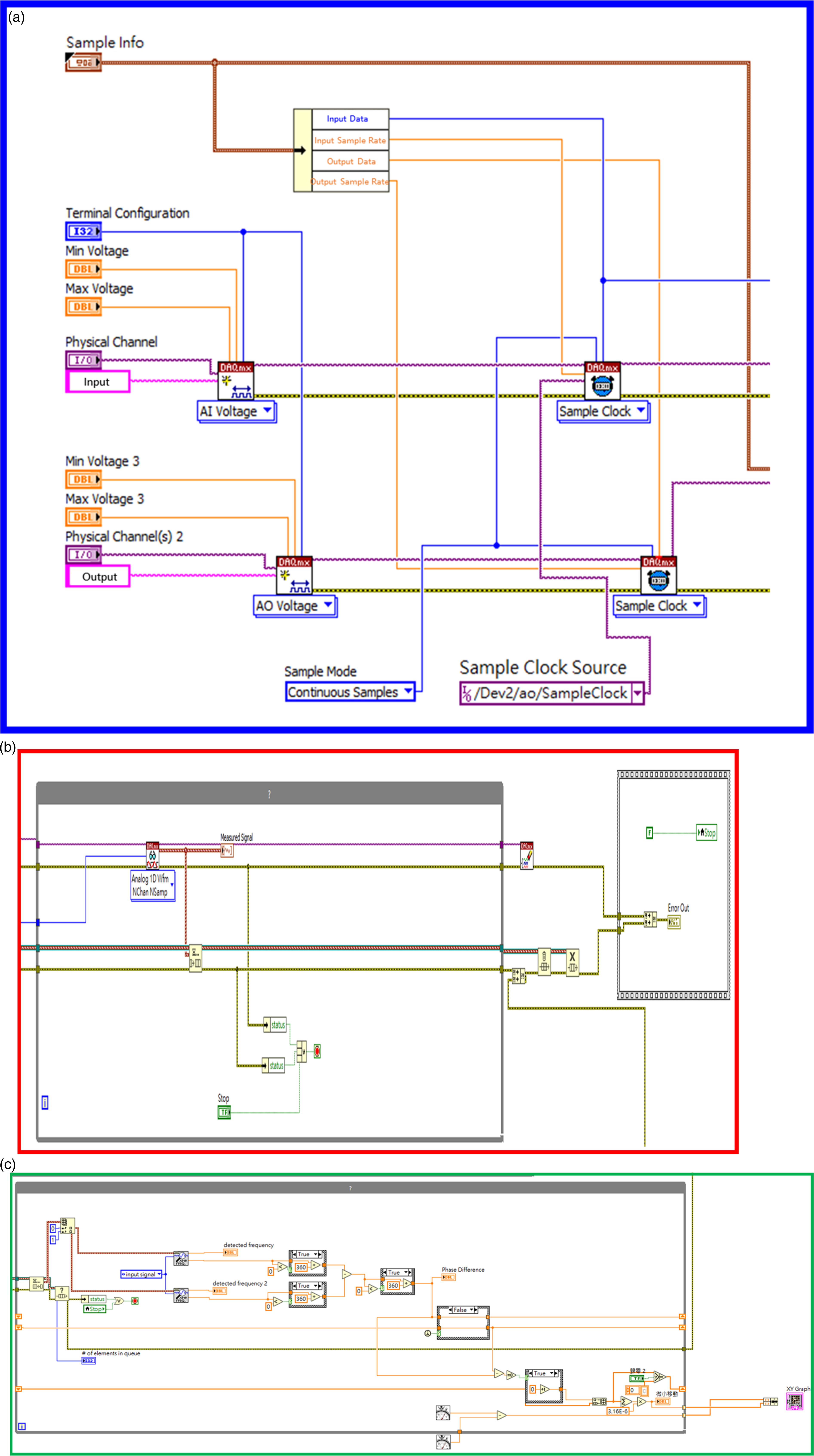
Experimental results of the prototype model
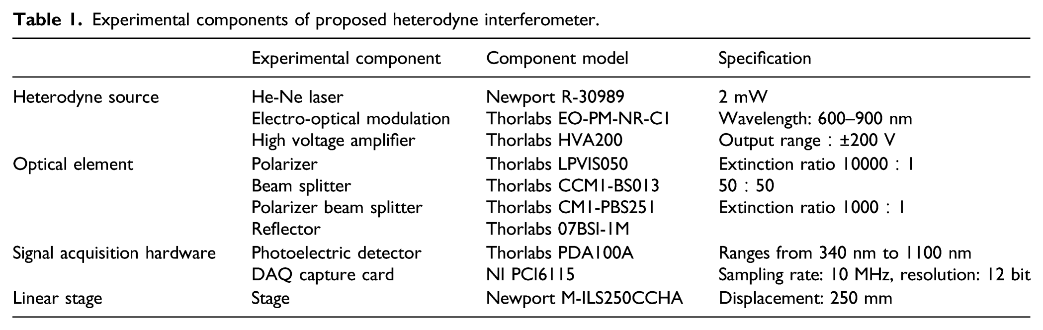
Experimental components of proposed heterodyne interferometer.
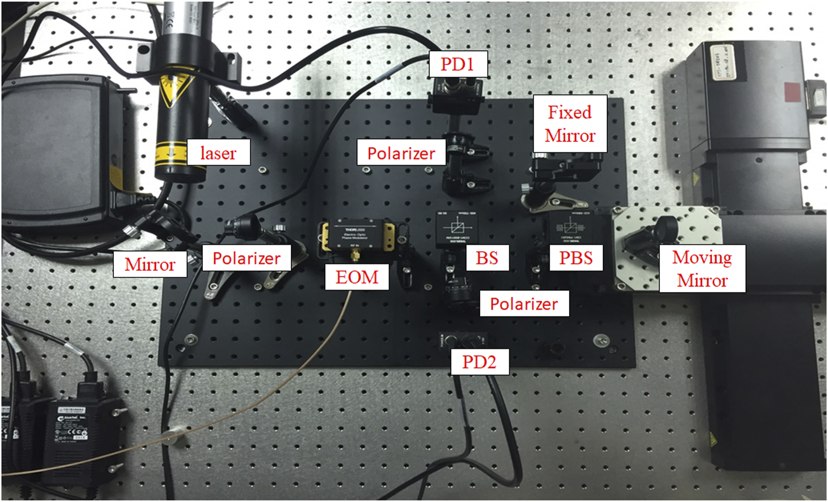
Laboratory-built prototype and measured long linear stage.
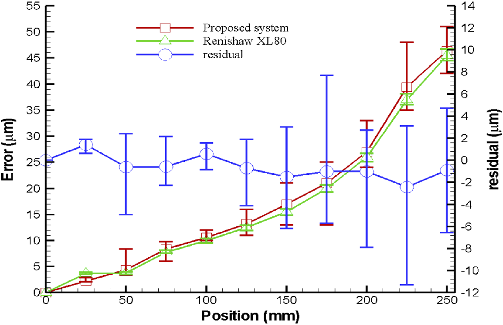
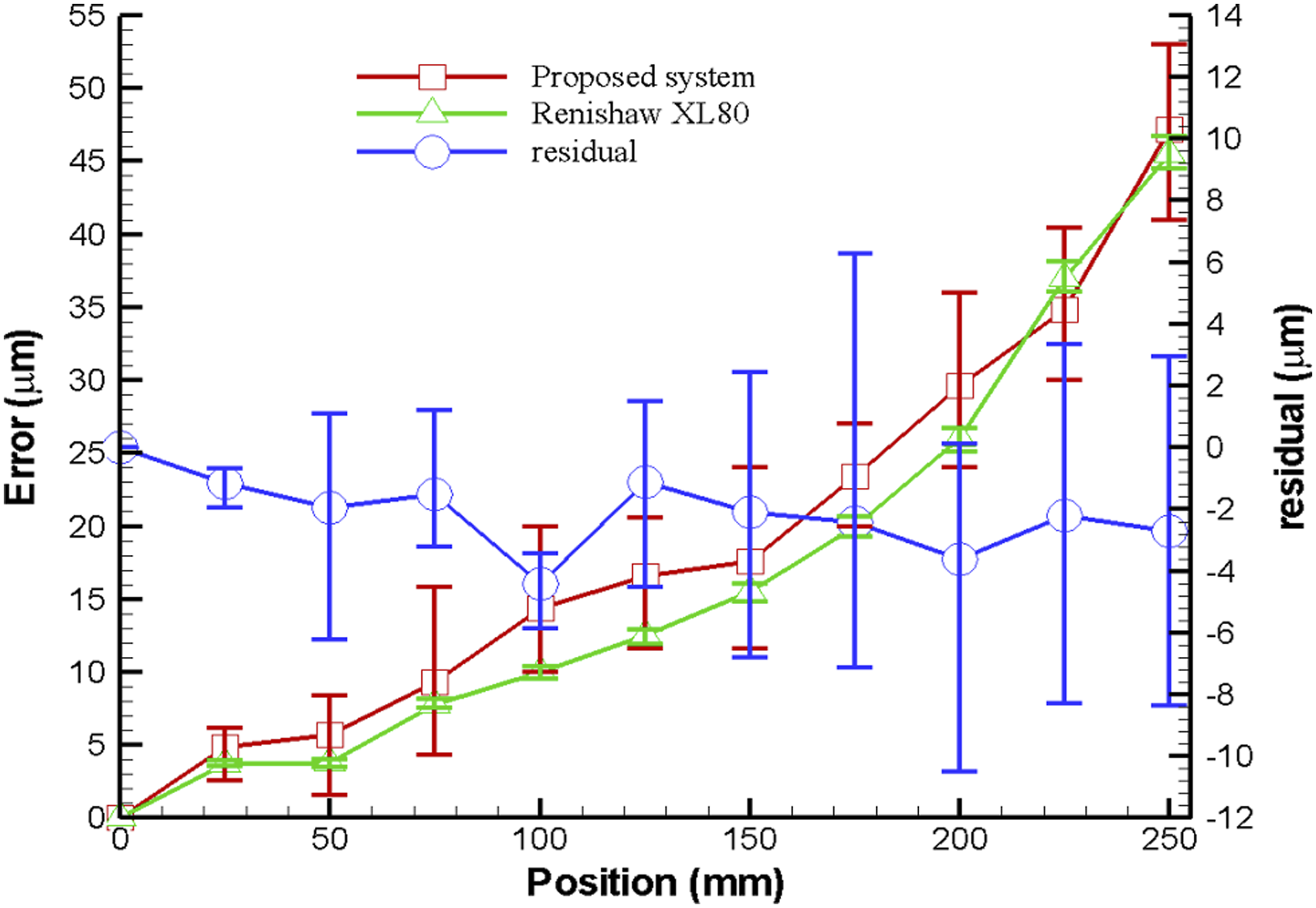
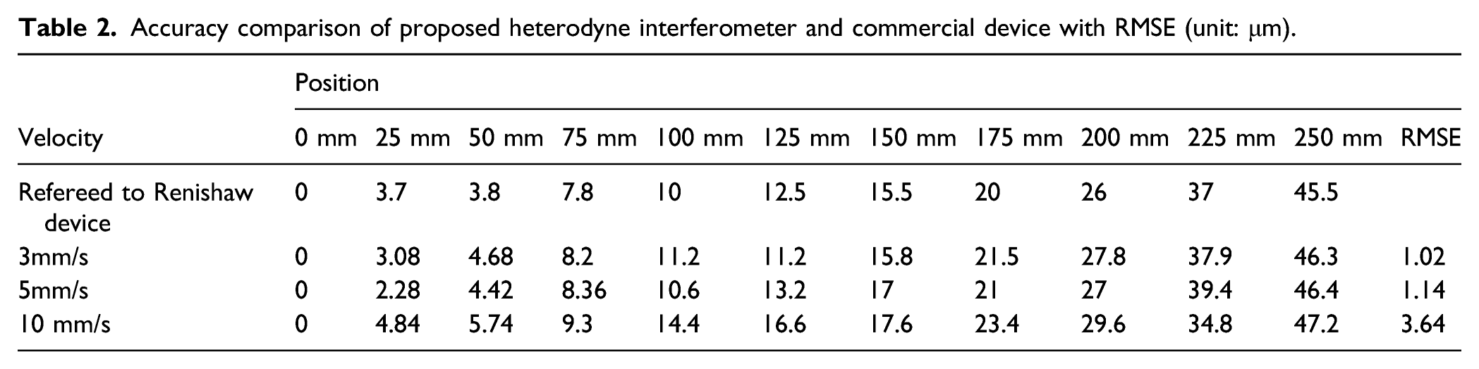
Figures 7–9 reveal the measurement results obtained for the positioning errors of the long linear stage at the three velocities. The measured positioning errors were consistent for the different velocities and had negligible differences. Table 2 lists the accuracy comparison of the proposed heterodyne interferometer and commercial Renishaw interferometer. The accuracy and root mean square error (RMSE) of each measuring point are based on tests conducted in triplicate. Experimental results for linear stage velocity of 3 mm/s. Experimental results for linear stage velocity of 5 mm/s. Experimental results for linear stage velocity of 10 mm/s. Accuracy comparison of proposed heterodyne interferometer and commercial device with RMSE (unit: μm).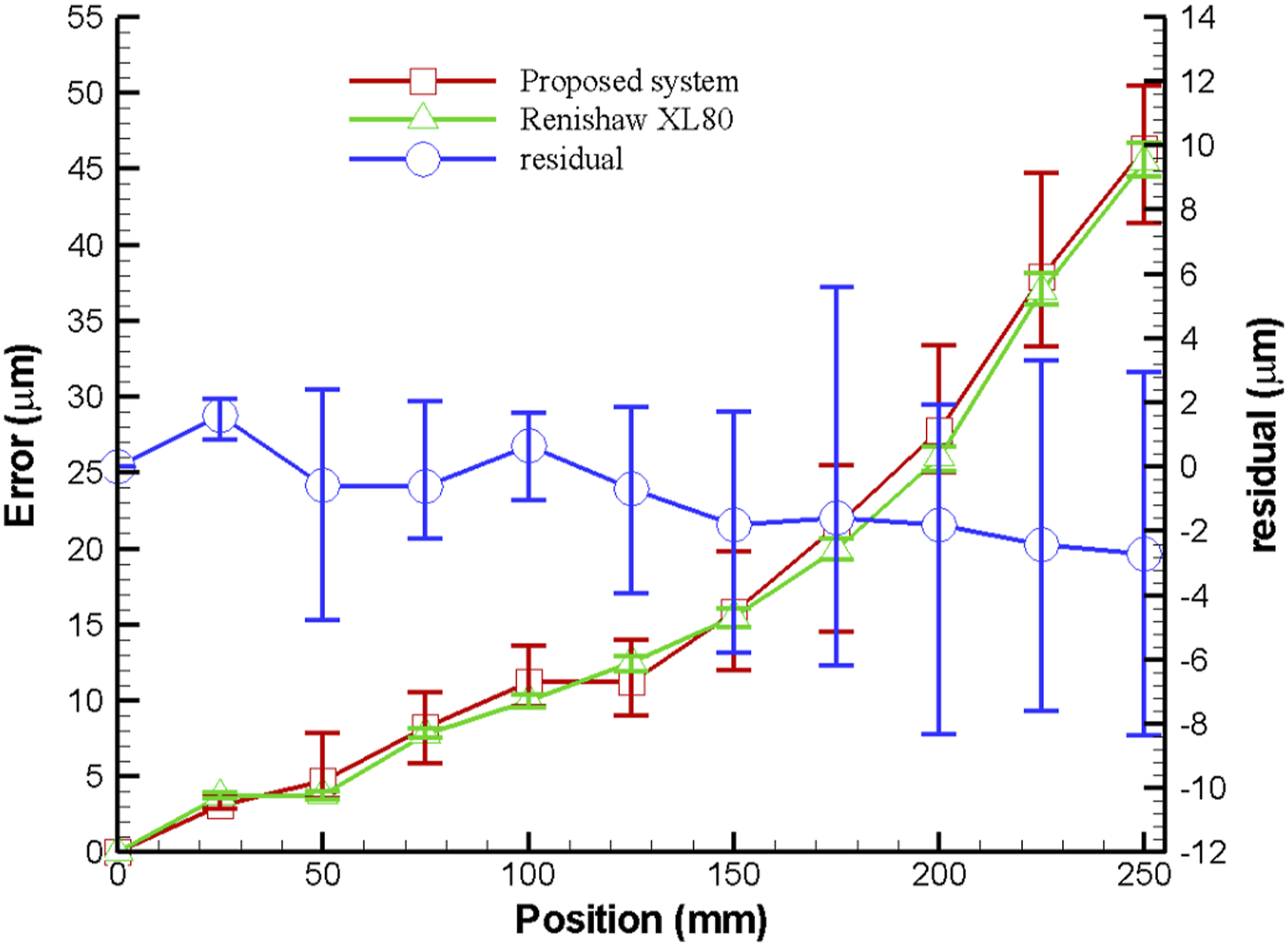
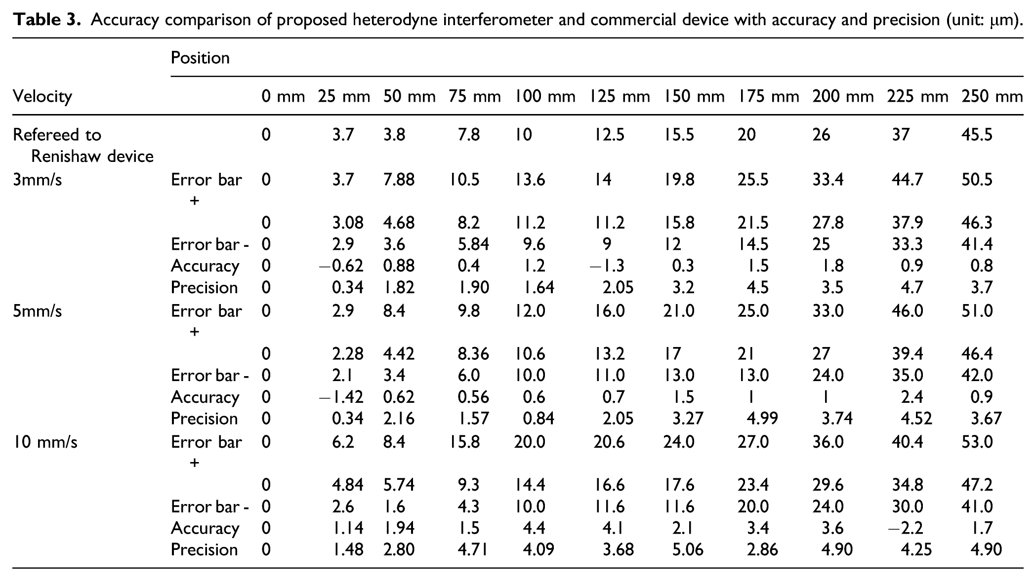
Accuracy comparison of proposed heterodyne interferometer and commercial device with accuracy and precision (unit: μm).
In summary, the experimental results demonstrated that the proposed heterodyne interferometer can be used for measuring the positioning error of a long linear stage with a traveling range of >200 mm, thus representing an alternative cost-effective solution for measuring the positioning error of linear stages with a long traveling range. In the future, the proposed heterodyne interferometer will be integrated into the previously developed precise and simple measurement system for simultaneously measuring 6-DOF geometric errors of a long linear stage used in machine tools. 1
Conclusions
In this study, a low-cost heterodyne interferometer configuration based on a virtual electronic phasemeter for measuring the positioning error of a long linear stage was proposed and verified. Unlike the commercial laser heterodyne interferometer used for the purpose of comparison (Renishaw XL-80), our interferometer has a photodetector-based configuration in combination with a virtual electronic phasemeter; moreover, a self-developed signal-processing technique is employed to process the signals from the heterodyne interferometer. The proposed core algorithm was demonstrated to be highly suitable for heterodyne interferometry. The effectiveness of the proposed heterodyne interferometer was verified through an experiment using a laboratory-built prototype. The experimental results indicated that the positioning accuracy of the proposed heterodyne interferometer was ±4.5 μm for a linear stage with a displacement of 250 mm; this result was highly consistent with that obtained for the commercially available laser interferometer, indicating that the proposed system is suitable for measuring positioning errors in linear stages with large displacements in real time and can thus be used in other applications related to precision engineering. This study focused on the self-developed photoelectric-signal-processing technique combined with the optomechanical configuration. To achieve device portability, the current dimensions of approximately 150 mm × 150 mm × 150 mm should be further reduced. Moreover, improving the measuring accuracy of the proposed heterodyne interferometer will be an aim of future work.
Footnotes
Declaration of conflicting interests
The author(s) declared no potential conflicts of interest with respect to the research, authorship, and/or publication of this article.
Funding
The author(s) disclosed receipt of the following financial support for the research, authorship, and/or publication of this article: The authors gratefully acknowledge the financial support provided to this study by the Ministry of Science and Technology of Taiwan under Grant Nos. MOST 105-2221-E-194-013-MY5, 106-2628-E-194-001-MY3, 108-2218-E-002-071, and 109-2218-E-002-006.