
Abstract
This study discusses the development process of a full-scale test facility composed of a high-performance radiant heating system, a life-sized instrumented thermal manikin system with sensing assemblies, associated equipment and in-house software controlling the entire system. This test system was aimed to be used to examine the behaviour of emergency-responder garments and subsequently to find weaknesses of turnout gears at critical thermal conditions greater than a standard 84-kW/m2-intensity, thereby contributing to improving the survival chance of firefighters who could be requested to execute an emergency evacuation from an unexpected growth of modern fires. To impose a target 126-kW/m2-irradiance throughout the garment-dressed manikin’s exposed surface for a limited period of time (12 s) as uniformly, consistently, stably and safely as possible, several technical aspects were considered: the amounts of heat-source power and electric power-supply; areas of heating and receiving and their geometrical relationship; a practical percentage of the maximum heater-capability; efficiencies of electric power-supply and water-cooling; movable equipment; and safety equipment. Two analytical models were encoded using a finite difference method in the LabVIEW platform to determine a burn injury distribution throughout the manikin-shell in association with the measurement data from the test system. The heating system and software were validated in respect of the heating consistency, vertical intensity variation, intensity-rise rate and discrepancies between the existing and present models. It was proved that the heating system is capable of increasing its heat emission up to 126 kW/m2 within 1.5 s, maintaining the intensity-level with less than 9-kW/m2-change for 12 s, and distributing the intensity-level with less than 11-kW/m2-variation along the vertical direction, from 45-cm- to 155-cm-height. The development process can contribute to the ability to develop a large-scale test facility to test specimens under a critical thermal exposure condition for research purposes.
Keywords
Introduction
The fire safety society has achieved advances in the understanding of fire behaviours in relation to heat transfer mechanisms in various engineering applications. Since the research field considers much higher thermal energy than typically observed in the living environment, these achievements have often been experimentally examined by using custom-made fire-test apparatuses. Researchers in the field of emergency-responder garments also use experimental instruments to assess the thermal protective performance of fabrics; the clothing is designed to act as a shield-like barrier to thermal hazards threatening professionals working in firefighter, army and car-racer roles. These evaluation apparatuses for fabrics’ thermal performance are designed to simulate a representative intensity of realistic fire hazards, which is governed by technical factors, such as the spatial location and geometry of fire sites, and the type and amount of materials (or fuel). Fire loads have varied over the years due to increases in residential geometries and use of flammable synthetic materials. 1 Features of modern fires, therefore, need to be reflected in creating a thermal condition to conservatively evaluate garments’ thermal protective performance for wearers’ safety.
Attention has recently been directed towards the fire safety for emergency responders in South Korea. Figure 1(a) and (b) show the ratios of fire-service fatality to casualty in three countries between 1980s and 2010s, and the percentages of spatial categories of 433,098-normal-fire and 55-great-fire events in Korea from 2006 to 2014, respectively; great fires refer to a fire hazard resulting in more than fire fatalities, 10 casualties or five billion Korean Won in damage and loss defined by the ministry of public safety and security of Korea. The fatality-to-casualty ratio of Korea is approximately over 10 times greater than those of the USA and England, and compartment fires in Korea account for 60.9% and 76.4% of the total normal and great fires, respectively. From the statistics, it can be inferred that (1) Korean firefighters still need improved physical protection against fire hazards during fireground operations to come up to the fire safety level of the other countries; and (2) their lives are often threatened by a critical thermal condition caused from modern compartment fires. Statistics with respect to the safety of firefighters: (a) the ratio of fire-service deaths to casualties in three countries; and (b) the proportion of compartment fire in the total number of fire events in South Korea.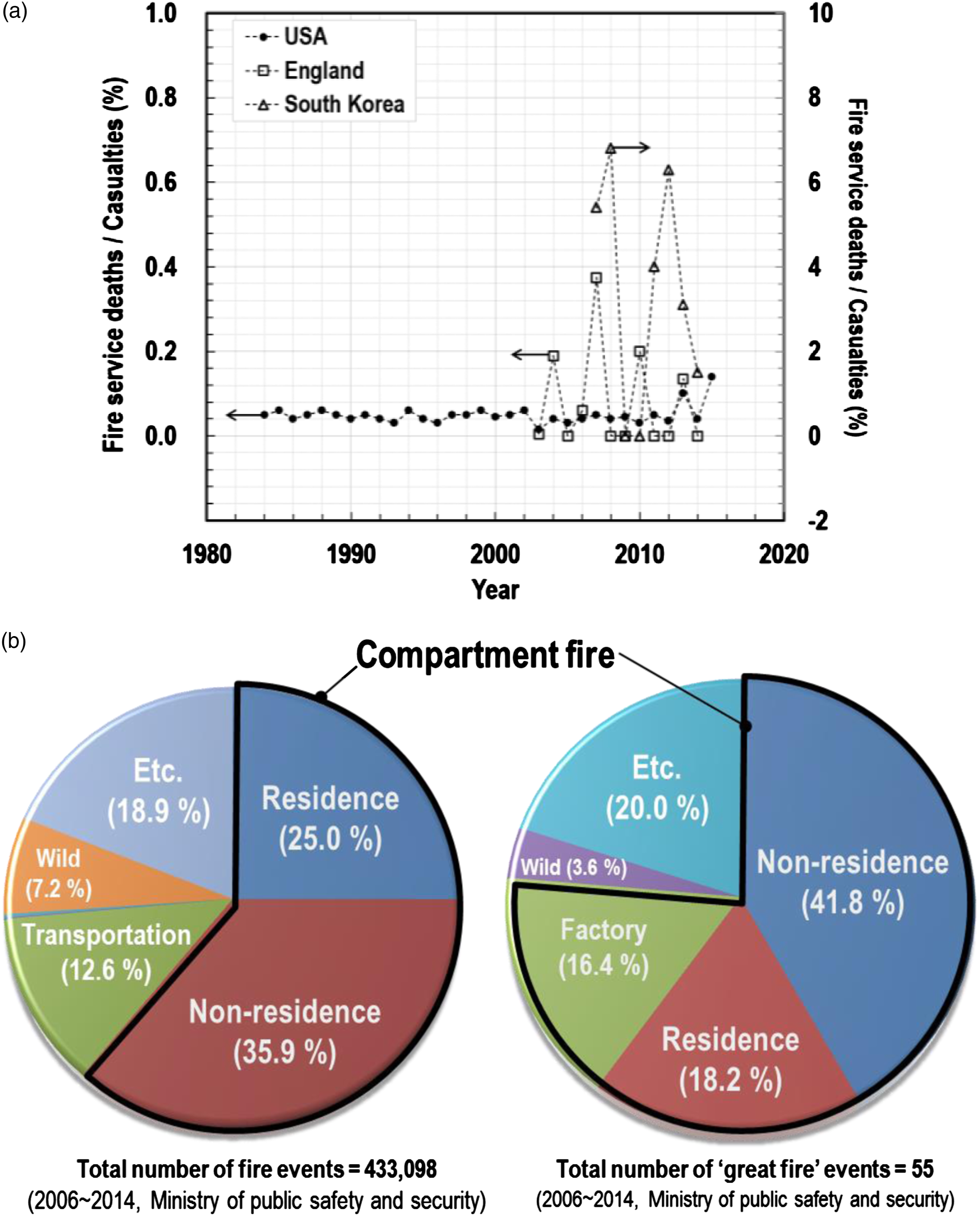
The critical condition for firefighters is generally defined as the flashover-, backdraught- or fully developed-stage. It was estimated that, when firefighters urgently egress from a compartment due to an unexpectedly rapid fire-growth beyond flashover (over 600 C), a tolerable limit of distance from the hallway for survival is just 1.5 m based on the presumptions of a crawling speed of 0.76 m/s and the maximum exposure time of 2 s. 2 Since an extremely low chance of survival is expected once exposed to the critical condition, firefighters should be trained to be acquainted with the indication of the onset of the stages and to evacuate from such dangerous places.
With respect to the emergency evacuation, many studies have dedicated to mitigate potentially life-threatening heat-stress for firefighters from several viewpoints: the protective performance against incoming heat and its requirements 3–4 ; the heat and moisture transfer mechanism across the fabric assembly with different conditions (air-gap, wet/dry or configuration) 5–7 ; the heat-stress impact on firefighters, regarding outgoing metabolic heat produced by the body, and its dissipation 8–10 ; and the test environment to examine the aforementioned performances of fabrics or garments. 11–13 To contribute to the improvement of firefighters’ survivability, urgently evacuating from modern fires, this research project is mainly focused on the protective performances of fabrics and garments and their evaluation. As part of the project, this paper comprehensively discusses the creation of a prerequisite test environment that enables one to examine functional limitations of full-scale thermal protective clothing under a higher level of thermal environment than the existing standard testing conditions employed in a thermal manikin test. 14 The test environment, proposed in this study, was devised to give assistance to the existing standard test methods that have limitations to create a critical condition to firefighters such as an emergency evacuation; features of existing methods are discussed in the next section to adapt their merits and to overcome their limitations for the apparatus development in this study.
The conventional thermal condition established in the testing field of thermal protective clothing was initially quantified by Behnke 15 as an intensity of 2 cal/(cm2•s), which is the average of the flash-fire intensity of 1–3 cal/(cm2s) recorded from a series of laboratory-scale tests. 16 Based on the reviews on the origin of the heat density and the characteristics of flash and compartment fires, this study proposed the upper radiant intensity of 3 cal/(cm2s), equivalent to 126 kW/m2 in SI units, for the worst-case scenario to examine the thermal protective performance and behaviours of garments subjected to critical thermal conditions.
In order to create the test environment, a group of high-performance radiant panels with a control program were developed from bench-to life-size. A bench-scale apparatus was initially designed to study the behaviours of small fabrics and equipment to protect body parts (hands, feet and arms), whereas the full-scale apparatus was to examine the aspects that cannot be covered by the work-table sized apparatus, such as the air-gap differential between the clothing and human skin created by body-curvature, and the degree of burn injuries throughout life-sized human-body. The research project includes a series of topics: (1) quantifying modern fire environments; (2) developing a bench-scale apparatus capable of creating the 126-kW/m2-radiant intensity; (3) establishing an instrumented manikin with heat flux sensors; (4) organising a data acquisition (DAQ) network that records outputs measured from dozens of points; (5) architecting an in-house software that controls the testing system and has functions to analyse heat transfers across human skin layers and degree of burn injuries; and (6) developing a life-size testing system. The topics from the third to the sixth were examined in this paper. The rest was discussed in a companion article by Kwon et al. 17
The features and limitations of the current apparatuses
In bench-scale tests, a small patch of fabrics or components (such as seams, zippers and pockets) of thermal protective clothing are exposed to a designed constant heat source, and the amount of heat transferred across the specimen-thickness is measured using a copper calorimeter. 11–12 The tests can contribute to the classification and selection of materials suitable for garments effectively in terms of cost and labour. However, they do not include several aspects affecting the garments’ performance, 5–6 such as the degree of fit, air-gap variation along the body-curvature and reinforcement caused by pockets and reflective trim, thereby having unsolved correlations between small-scale test results and actual performances of life-size garments. Therefore, the bench-scale tests are yet unable to allow an overall evaluation of the garments’ thermal protective performance.
To cover the limitations of bench-scale tests and assess the overall protective performance of garments, a representative regular-40-sized turnout gear including design features is subjected to a flame engulfment in conformity with ISO/DIN 13,506-1, 14 using a test system composed of two major parts: a measuring part with an upright life-sized flame (or flash-fire) manikin and a heating part with propane-diffusion-flame burners surrounding the manikin. Several instrumented flame manikins have been developed by research groups, such as Natick Laboratories, Dupont in conjunction with the US Air Force, NC State University, the University of Alberta, British Textile Technology Group, Swiss Federal Laboratories for Materials Science and Technology, and Aitex Certification Laboratory. 18 In general, manikins are made of flame-resistant polyester resin reinforced with fibreglass. A minimum of 110 sensors, such as skin simulant sensor and copper-slug calorimeter, are uniformly distributed throughout the manikin-shell. Their leads are mainly embedded inside. The heating system includes 8–12 burners positioned at the angular points of a hexagon at the vertical levels of knee and thigh to create a condition of flame-engulfment exposures to the manikin as uniform as possible for a specific short exposure time. The power of burners is regulated at a level within which the average heat flux measured for all the nude manikin sensors is a nominal level of 84 kW/m2 ± 2.5%.
The full-scale evaluation system allows researchers to observe phenomena visually, such as the ignition and burning of the garment, the structural failure of components, and sagging or shrinkage in all directions after flaming, as well as to analytically examine the data measured and calculated, such as temperature, heat flux and degrees of burn injuries.
13
However, there exist its potential limitations for advanced evaluation, as follows: 1. The standard deviation of the average heat flux calculated for all the heat flux measurements is guided as less than 20 kW/m2.
14
However, more accurate information on the amount of thermal energy originating from the multiple burners and arriving at the specimen’s exposed surface needs to be provided. In this respect, firstly, the diffusive flame-tips, ejected from the multiple burners’ nozzles, are highly fluctuant during engulfing the specimen. Secondly, although the heat-quantity is considered to be fully managed by mechanical valves regulating the flow rate of the gaseous fuel inside pipes, it takes a few seconds for the pressure of gas ejection to emit stable flames; the evaluation test is conducted for a few seconds, typically up to 12 s. The second limitation could be overcome by installing a high-performance carburetor; and 2. Practical difficulties exist on flame-exposure uniformity throughout the garment’s exposed surface. Although the complete uniformity may not be achievable during testing in practice due to the body-curvature, at least heaters should remain the consistency of heat emission, and the quantity of the incoming heat on each of the specimen’ surface-regions needs to be predictable.
The conventional thermal environment enables one to rank turnout gears in terms of thermal protective performance. However, it has limitations on use to examine the heat transfer mechanism from the clothing’ exposed surface, through fabric layers with air-gaps, and to the manikin’s skin sensor so as to find weaknesses and improve the garment’s protective performance, since the quantity of the incoming heat is one of the primary factors to analyse such heat transfer mechanism. A thermal manikin system, named as RadManTM, was recently developed by NC State University. 19 In the development, new attempts were made to cover the limitations of the conventional methods, such as a life-sized gas-powered radiant heating panel as a more stable heat source than diffusive flame burners, a water-cooled thermal shield to block the undesirable heat, an internal water-flow system simulating blood-flow, and a foil sensor (made by RdF Corp.) to reduce the heat saturation effect. The heat emission range of the heater was moderate as from 5 to 21 kW/m2.
Development of full-scale apparatus
General
A full-scale test system capable of creating the 126-kW/m2-radiant intensity was developed to examine the thermal protective performance and behaviours of garments at critical thermal conditions. This facility is composed of (1) a thermal chamber, (2) radiant heaters, (3) a thermal manikin instrumented with sensors, (4) a rail trolley and thermal shields operated by pneumatic pumps and (5) a DAQ system controlled by an in-house software.
Thermal chamber
In order to construct a thermal chamber for the full-scale test system, several auxiliary aspects should be fulfilled as follows: a 3-phase AC-380-V/1,600-A electric power system with control panels to operate heaters; a water-supply system to cool heaters down; a fire-resistant compartment; a ventilation-and-dust-collection system; a constant temperature-humidity system to maintain initial test conditions; and an emergent fire-extinguishing system. Figure 2(a)–(c) show the architectural plans of the thermal chamber and the layout of the test system. The inner walls of the chamber were covered with fire-resistant boards and a large explosion-protection glass window was installed on one wall to monitor tests. Only the heater-set, the instrumented manikin-set, the ventilation-dust-collection hood, a part of the DAQ system were placed within the chamber and all the system was controlled by the in-house software away from the test room. Architectural plans of the thermal chamber: (a) a bird’s eye view; (b) an architectural plan; and (c) a section.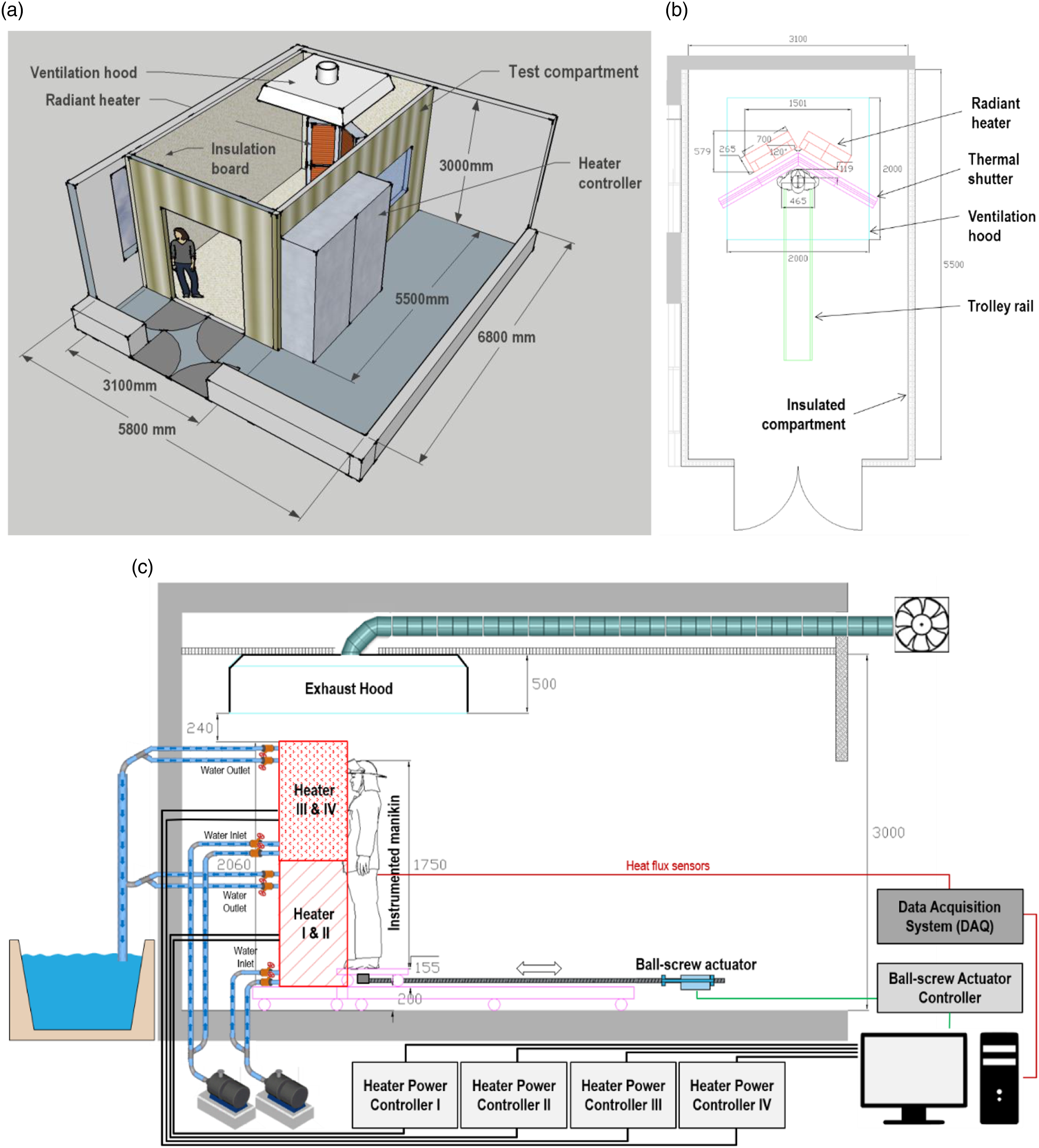
Radiant heaters
The radiation heating system was scaled up from a small-scale heater, through a bench-scale heater, and to the full-scale heater, which were introduced in the author’s other publications. 17,20 To impose a 126-kW/m2-irradiance throughout the full-scale manikin body as uniformly/consistently as possible, four technical aspects were considered: (1) the total heat-source power; (2) the geometrical relationship between the heating area and receiving area; (3) a practical percentage of the maximum heater-capability; and (4) the efficiencies of electric power-supply and water-cooling.
Based on the practical knowledge from the bench-scale heater development,
17
it was estimated that a receiving area of the manikin and a heating area of heaters are approximately 1.15 and 2.10 m2, respectively, thereby designing the corresponding total electric power as 756 kW, and proposed a 120-degree-angle layout for uniform irradiance on the specimens, as described in Figure 3. This design allowed the full-scale manikin body distanced approximately 300 mm from the heating area to receive the desired irradiance at around 70% of the maximum heater-capability. To supply such quantities of electric energy for the heating system, a 3-phase AC-380-V/1,600-A electric-power switchboard with circuit breakers was connected to the main electric-power system through two sets of 3-phase 300 sq mm cables. The spatial layout of the instrumented manikin and heating system.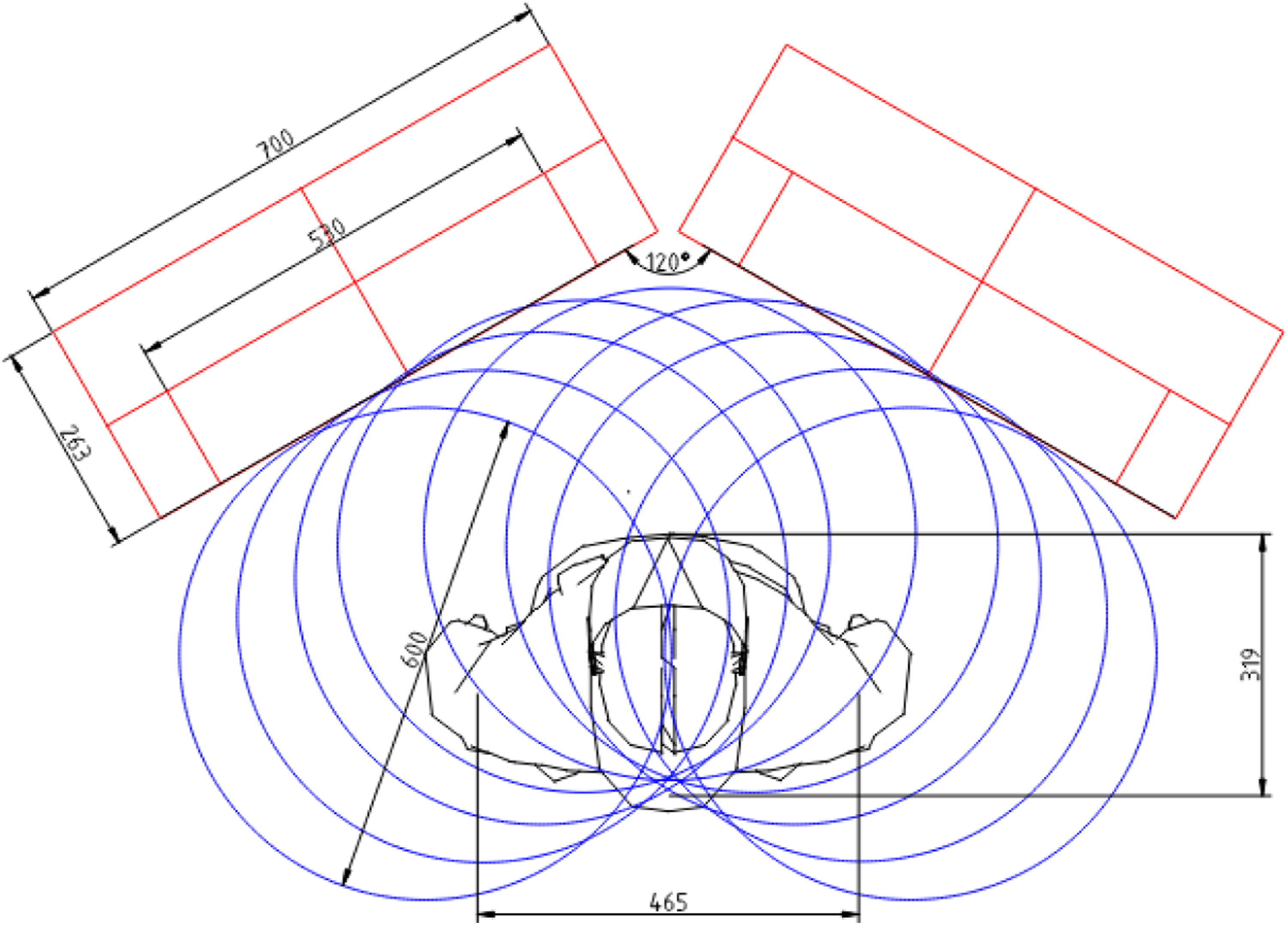
To achieve the efficiencies of electric power-supply and water-cooling, the full-scale heating system was separated from four heating panels, as shown in Figure 4(a). A single heater was designed to have 62 505-mm-length infrared halogen tubular quartz lamps (189 kW in total) installed in a 700 × 270 × 1030-mm stainless-steel frame (width × depth × height, SUS 304/430), as described in Figure 4(b). Each of the four heaters was individually connected to a 4-20-mA proportional-integral-differential (PID) controller installed in a heater-control panel that was connected to the electric-power switchboard through 3-phase 50 sq mm cables, as shown in Figure 4(c) and (d). For health and safety concerns, the maximum current flowing into the single heater was limited as 400 A, and total nine circuit breakers were installed in the electric-power switchboard and heater-control panel to shut down the electric power, in case of electrical failures. For the water-cooling system, a tap-water inflow with a flow rate greater than 20 lpm and an inlet temperature lower than 22 C was proposed to prevent any potential failures of the electrical part, heating elements and the stainless-steel frame from being over-heated, as shown in Figure 4(e). A mounting frame was constructed to provide the stability of the large-slenderness-ratio heating system, as shown in Figure 4(f). Notably, the heater consumes a large amount of electric energy only for a short period of time at the beginning of rapidly increasing the halogen-lamp temperature from room temperature. High-performance radiation heating system: (a) the front view of the heating system, (b) the front elevation and side section of a single heater, (c) the heater-control panel, (d) the electric-power switchboard, (e) the water-cooling system, and (f) the heater-mounting frame.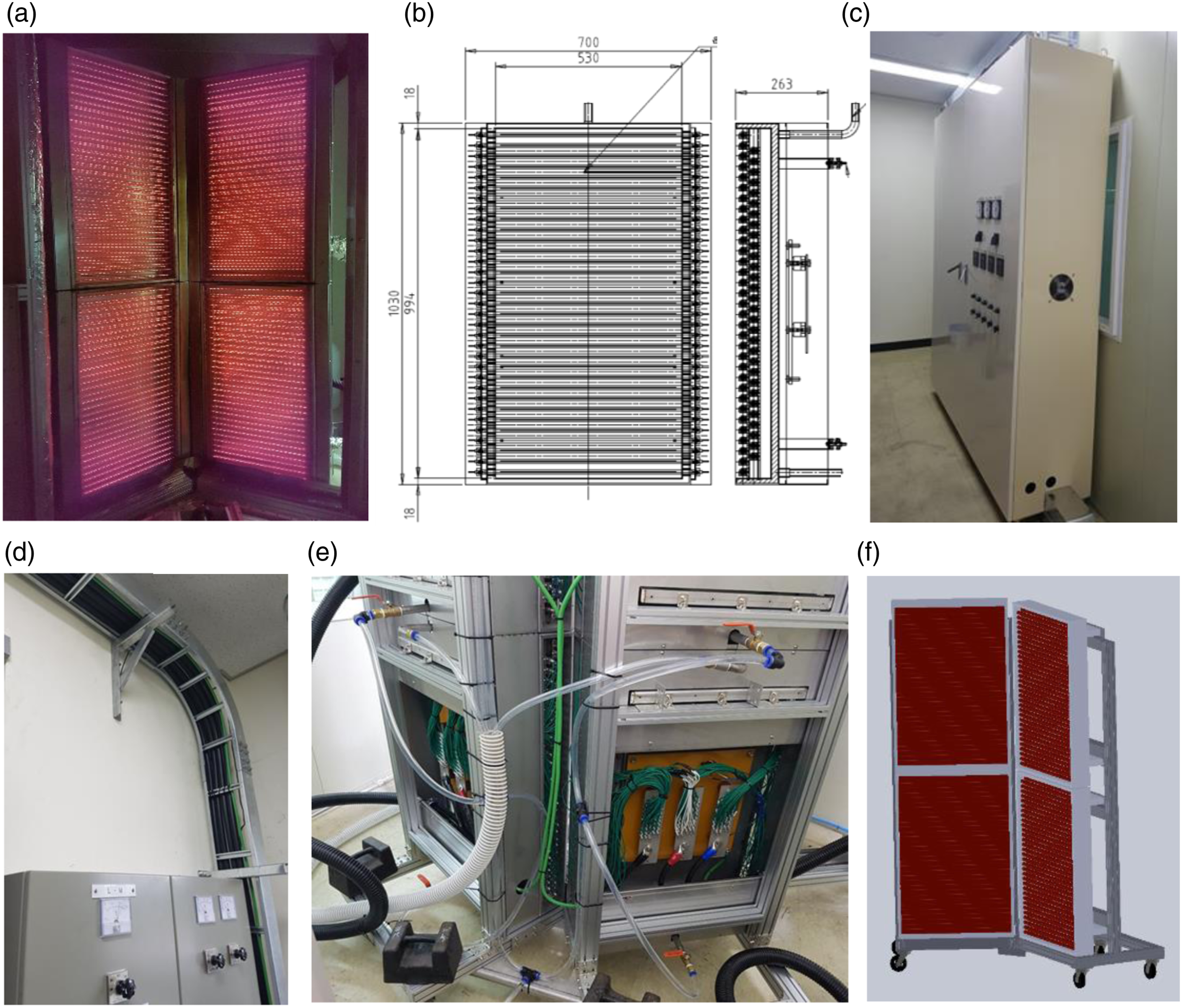
The full-scale heater should be thermally stabilised for a limited period of time after the activation. In the interim, to prevent any potential exposure of the test sample-dressed manikin to critical irradiance, thermal shields and a trolley on rails were developed, as shown in Figure 5. Since the exposure time of specimens to the heat source was set in a short range of 3–12 s in testing, the two shields closed at the onset of heating were supposed to be opened quickly after the heater-stabilisation stage. Two pneumatic pumps enabled each of the shields to be opened and closed within 1.5 s. In addition, the instrumented manikin stayed ready on the rail trolley distanced 2.5 m during the thermal stabilising and subsequently moved toward a predetermined position in front of the heat source by a ball screw linear actuator, not to be exposed to any potential irradiance before testing in collaboration with the movable thermal shields. To facilitate controlling the two motions methodically, an algorithm was encoded in the in-house software. The full-scale thermal heater-manikin system in the chamber.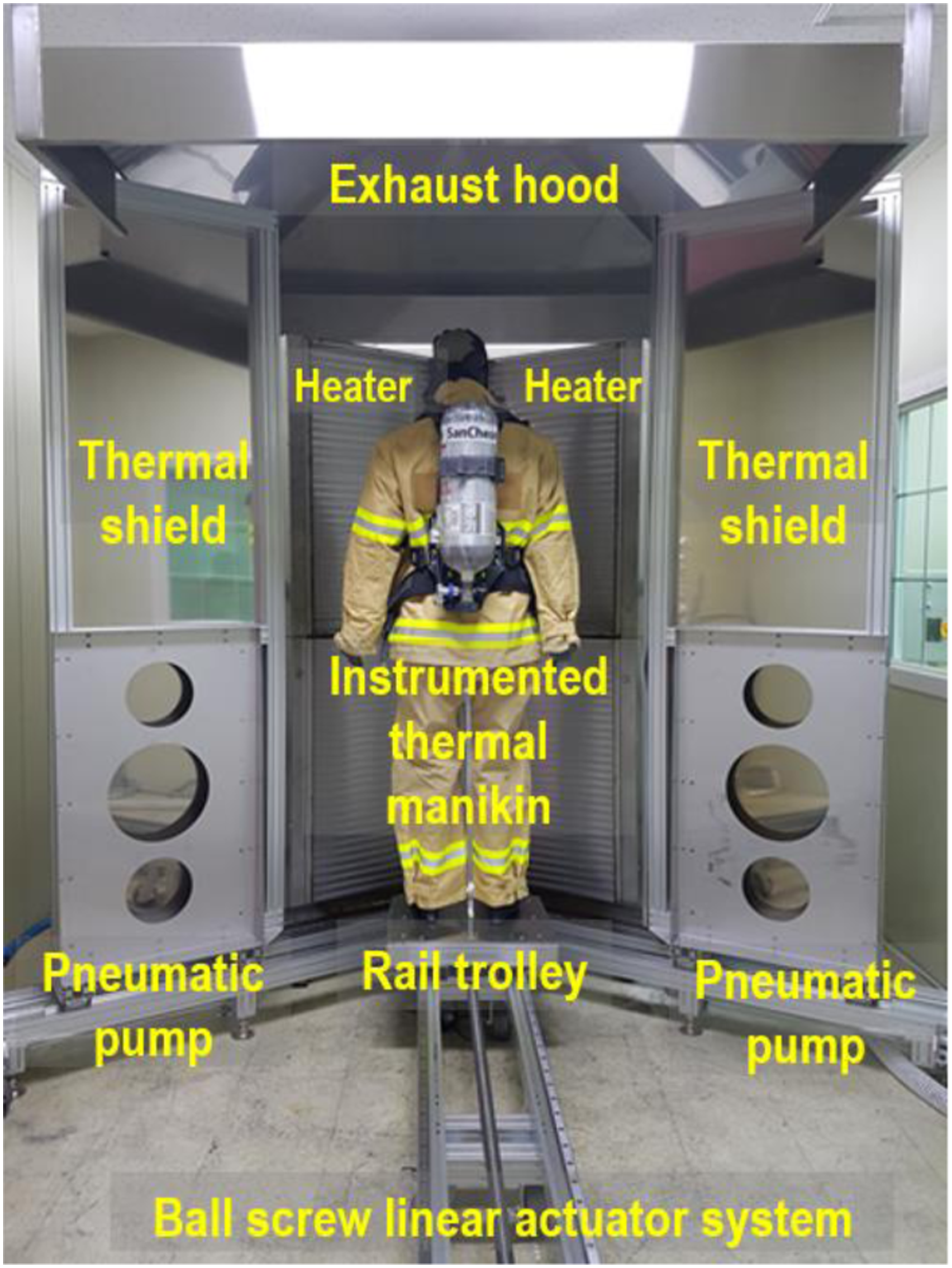
Instrumented thermal manikin
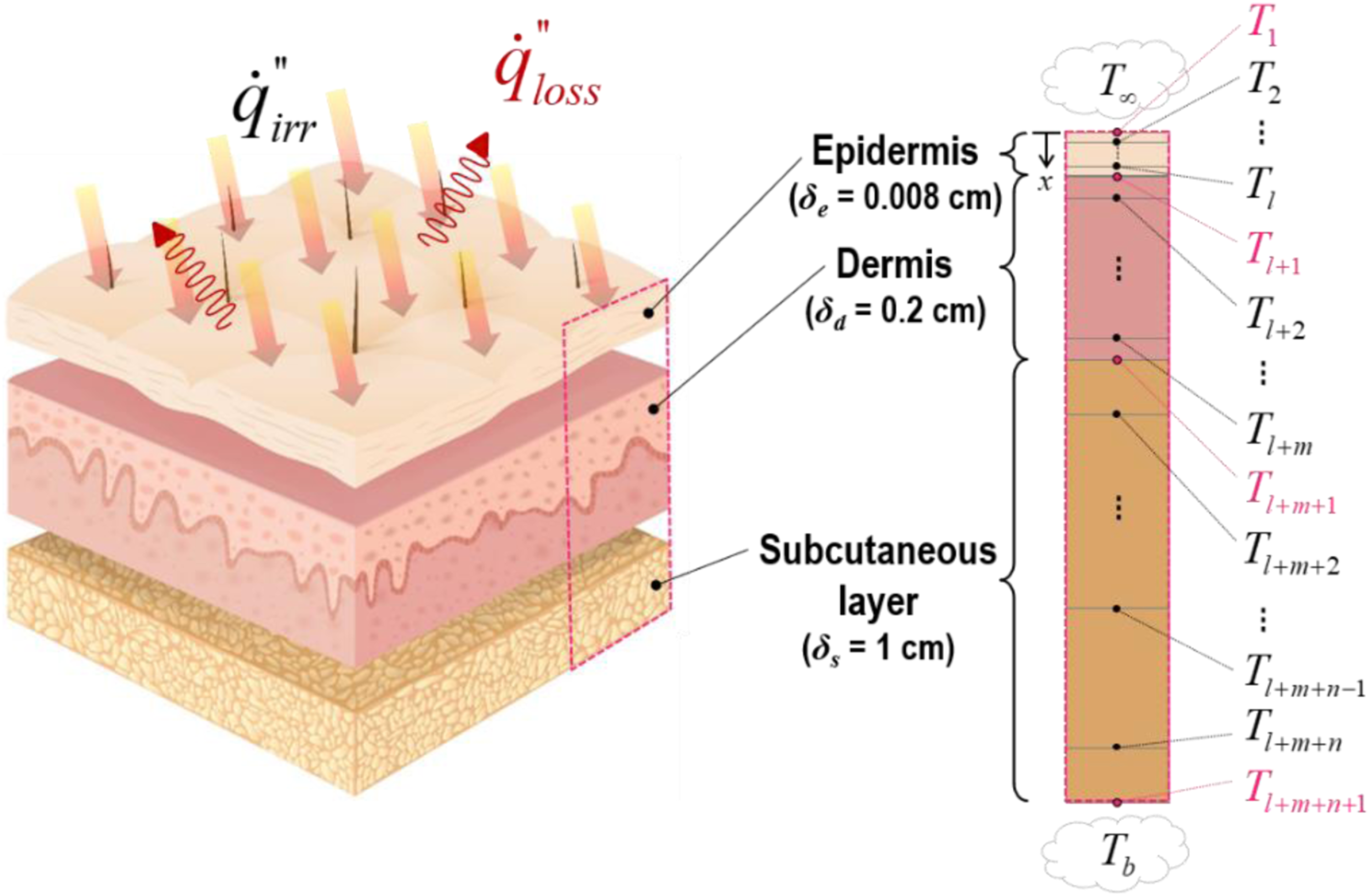
The thermal protective performance of garments can be evaluated by measuring accumulated thermal energies that are transferred across the clothing and air-gaps between the three-layered fabrics, subsequently arriving at the exposed surface of the human skin and the interfaces between the epidermis, dermis and subcutaneous layers. To simulate the assessment mechanism, a purpose-built life-sized manikin body, instrumented with heat flux sensing assemblies, was developed.
Figure 6 shows the instrumented manikin system in detail. The manikin-shell was made of fire-resistant polyester resin reinforced with fibreglass, jointed at the neck, shoulders, elbows, hands, pelvis and knees, and sized on the basis of the data on the 50th percentile physique of Korean males in the ages of 20–59 years,
21
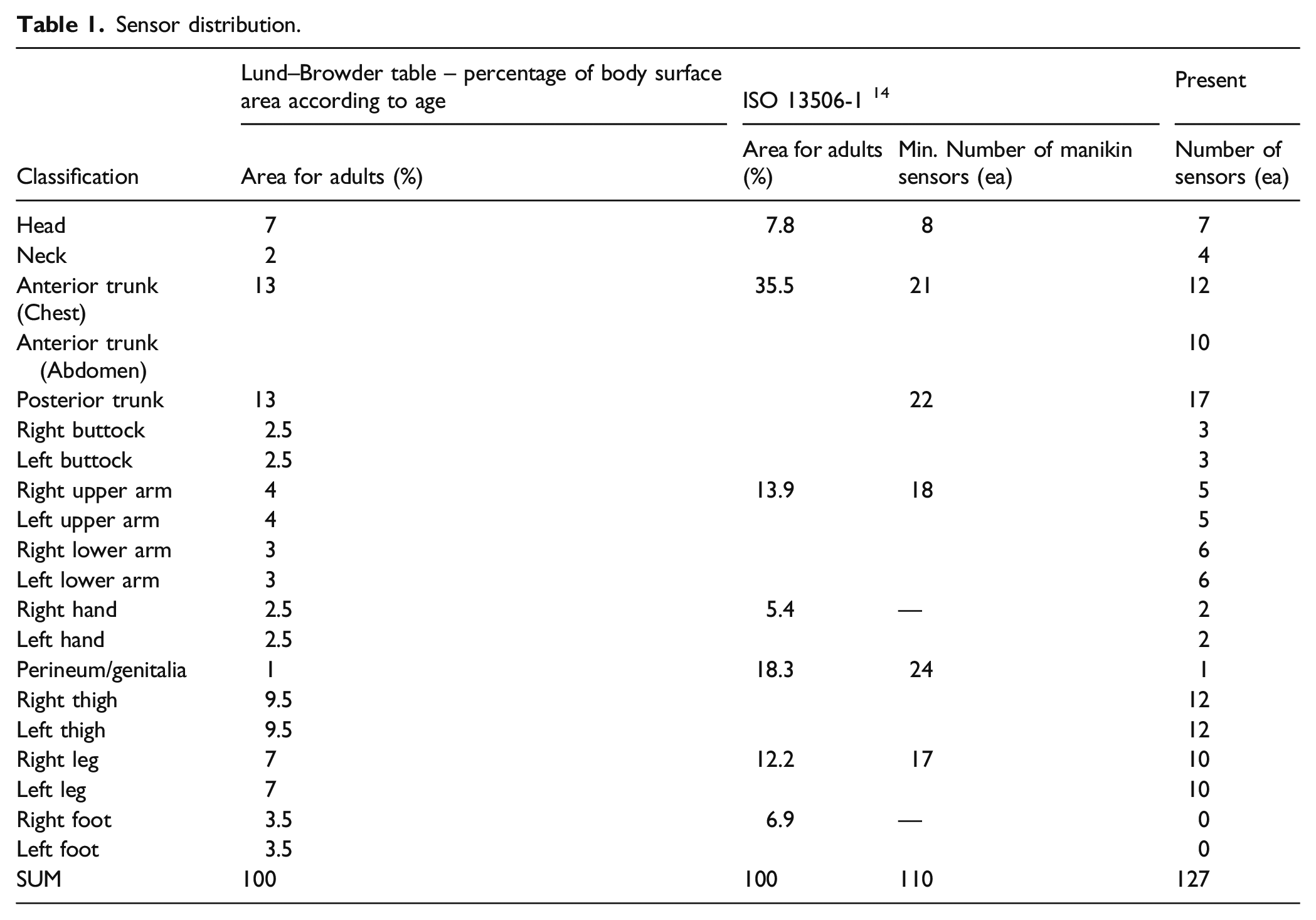
as shown in Figure 6(a). To firmly embed the sensing assemblies in the manikin body, the shell-thickness was designed as at least 4 mm. Considering the existing standard,14 127 sensing assemblies were distributed throughout the manikin-shell except the feet region, as shown in Figure 6(b); Table 1 demonstrates the number of sensing assemblies and the corresponding body parts and surface areas. Heat flux probe leads were configured through a drilled hole on the lower buttock-region to be connected to the DAQ system located outside the manikin body. The instrumented thermal manikin system: (a) the manikin physique and heat flux sensor; and (b) the schematic of sensor mapping. Sensor distribution.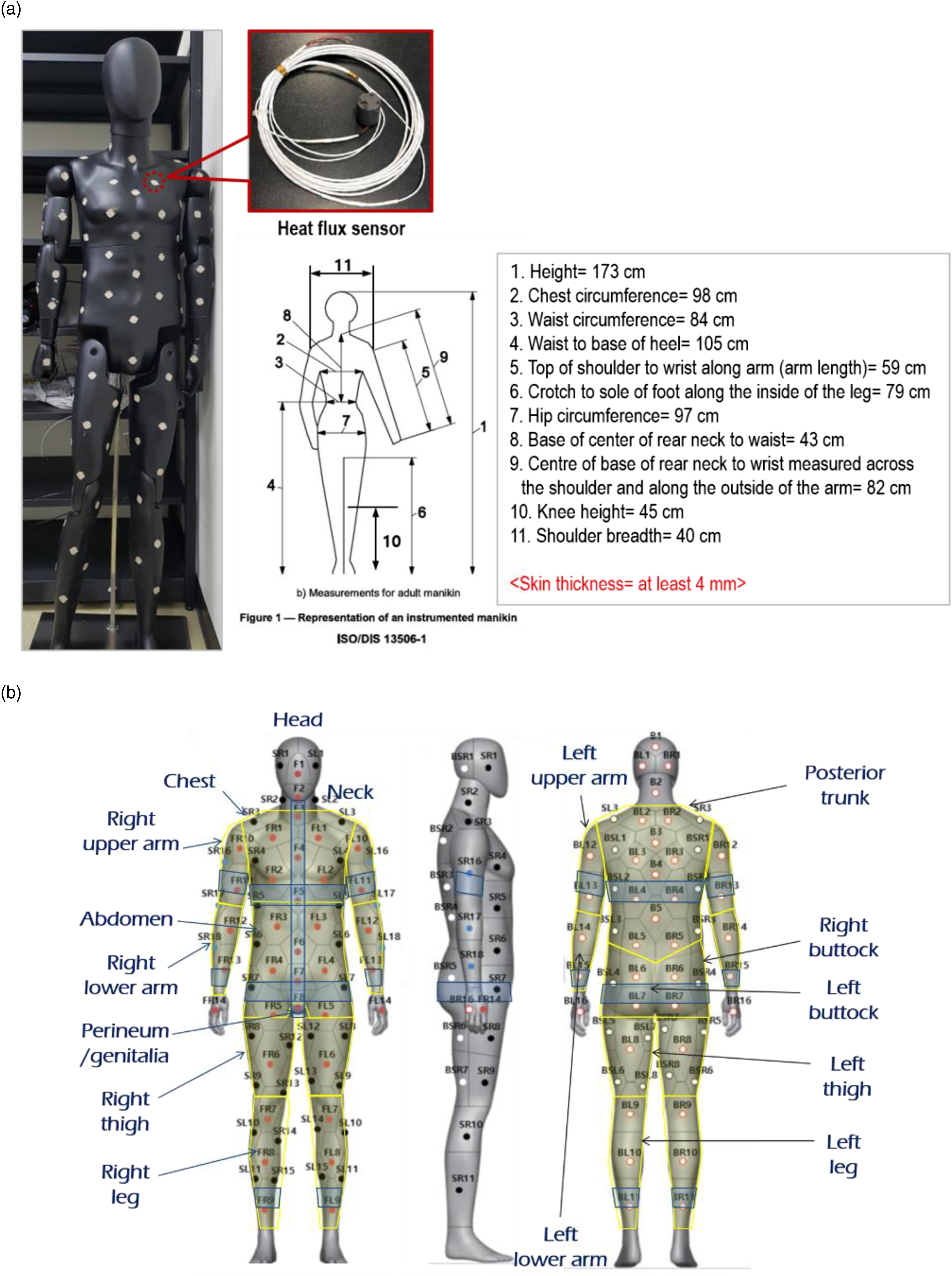
A thermoelectric heat flux probe, based on the Seeback effect (i.e. gSKIN® made by greenTEG), was employed to make the custom-made sensing assemblies. The probe was mounted in a PEEK-cylinder, filled with a skin simulant polymer. The probe’s back surface was adhered to the polymer surface with thermal conductive adhesive tapes, so that the sensing assembly is capable of reflecting voltage-signal variations that are caused by the thermal characteristics of the skin simulant polymer in measuring process; the composite polymer was made of silicone mixed with zinc oxide in the laboratory-scale tests, thereby having a thermal inertia comparable to that of the skin tissues, as shown in Figure 7. The exposed surface of the assemblies was covered with a thin layer of flat black paint with a thermal absorptivity greater than 0.9. Thermal inertia data of skin layers and ZnO-Silicone composites.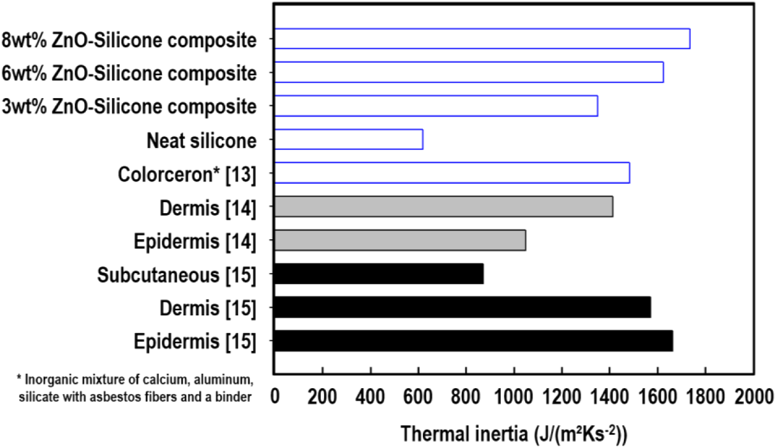
Modelling of burn injury evaluation in the in-house software
The data-set of the incident heat fluxes throughout the exposed body surface underneath the thermal protective fabric layers, obtained from the instrumented thermal manikin system, were directly input in two analytical models encoded in LabVIEW to calculate the temperatures at the interfaces between the epidermis, dermis and subcutaneous layers as functions of both time (t) and skin-depth (x): a skin model was developed by Mehta and Wong 22 and a burn model originated from Henriques, 23 and the former transient heat transfer equation encoded in the software is expressed in equation (A1) in Appendix.
To solve the linear parabolic partial-differential equation, finite-divided differences were substituted for the partial derivatives, as expressed in Equations (A2)–(A5) in Appendix. Subsequently, an algebraic matrix was derived using the Crank-Nicolson method (θ = 1/2), as follows
Elements of the tridiagonal matrix, [X], and the matrices with one column, {T} and {D}, are detailed in equation (A6) in Appendix; Table A1 shows the physical properties of materials used in the model, and the corresponding FD model is described in Figure 8. For initial conditions, the skin-layer temperatures and time-increment were set as 32.5°C and 0.1 s, respectively. The perfusing blood (or internal body) temperature was assumed to be maintained at 37°C during testing. The model’s boundary conditions were defined as follows The schematic of the human-skin structure and the corresponding finite difference model.

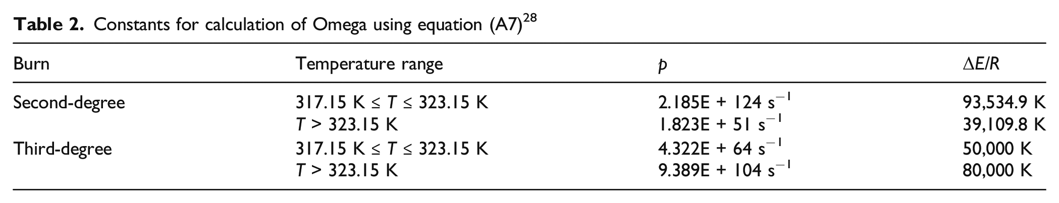
Burn injury criteria 23 .
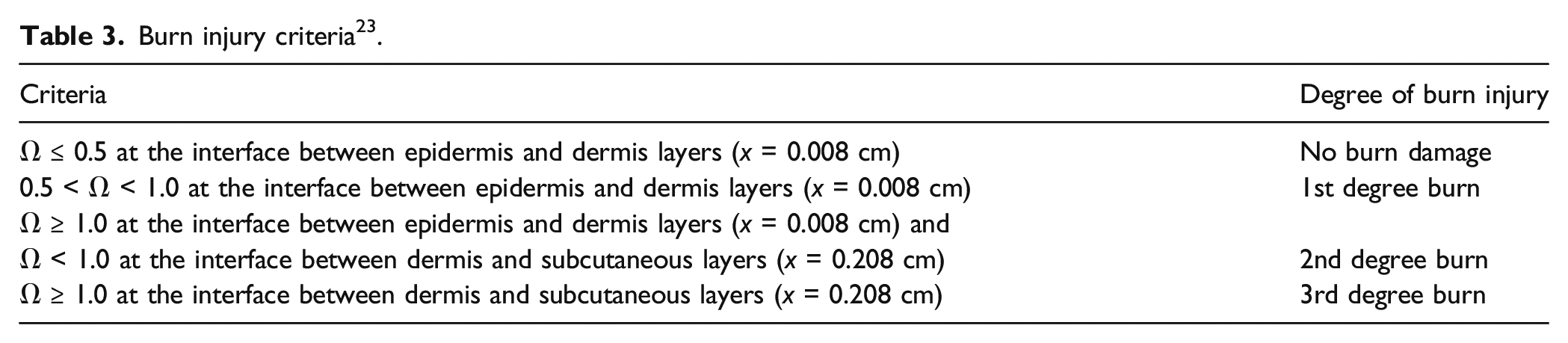
Figure 9(a) shows a screenshot of the test-system operation part in the in-house software, which controls the four heaters, the movable thermal shields and rail trolley, and the DAQ system. Figure 9(b) shows the skin and burn-model part, illustrating a prediction of burn injury distribution throughout the body on the left-hand side, time-dependent graphic profiles on the upper right-hand corner, and tabulated data of measurement and prediction on the lower right-hand corner. Screen shots of LabVIEW-based in-house software: (a) the system operation part; and (b) the skin- and burn-model part.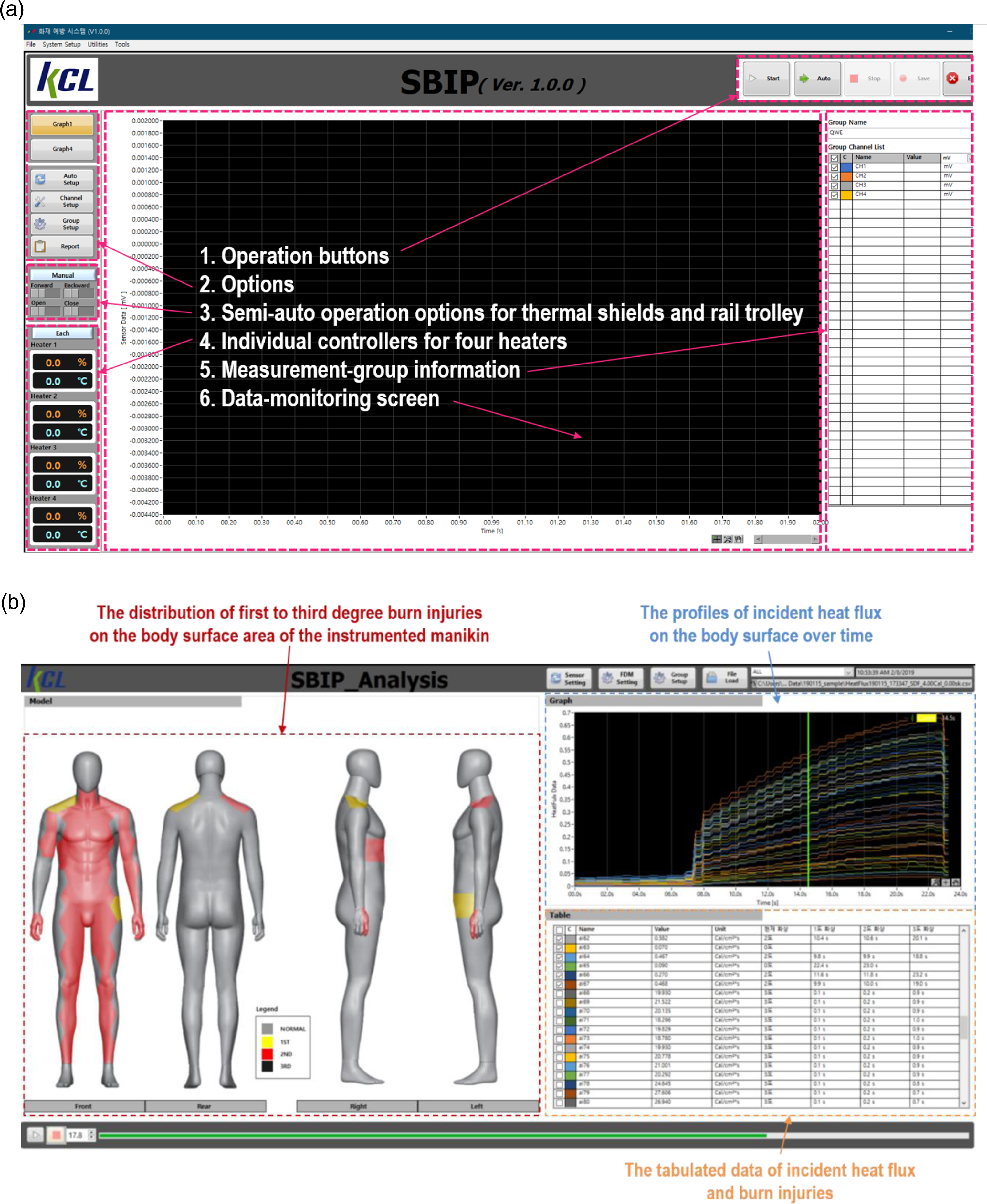
Results and discussion
Validation of the full-scale heater
The heating system was designed to impose an irradiance of 126 kW/m2 throughout the exposed surface of the garment-dressed manikin distanced 300 mm from the heater at around 70% of the maximum heater-capability. To validate the system’s performance, three aspects were examined in a preliminary test: (1) the quantitative stability of emitting heat for a testing period (up to 12 s); (2) an intensity variation along the vertical direction; and (3) the time to increase the intensity up to 126 kW/m2. For the test, three Schmidt-Boelter heat flux gauges were configured vertically at the positions, at which the knee, stomach and chest regions of the manikin were located (i.e. at the heights of 45, 100 and 155 cm, horizontally distanced 300 mm from the heating area). The heater-capability was discretely increased in 5% increments from 20% of the maximum capability to a particular percentage at which the probe received the irradiance of 126 kW/m2, as shown in Figure 10(a); the black, green and red lines denote the measured heat flux, the difference between the largest and smallest heat fluxes measured using the three probes at a corresponding time, and the percentage ratio of the difference to the largest value, respectively. The performance of the heating system: (a) the time-heat flux variation with the change of heater-capability; and (b) the graph zoomed in for a close-up.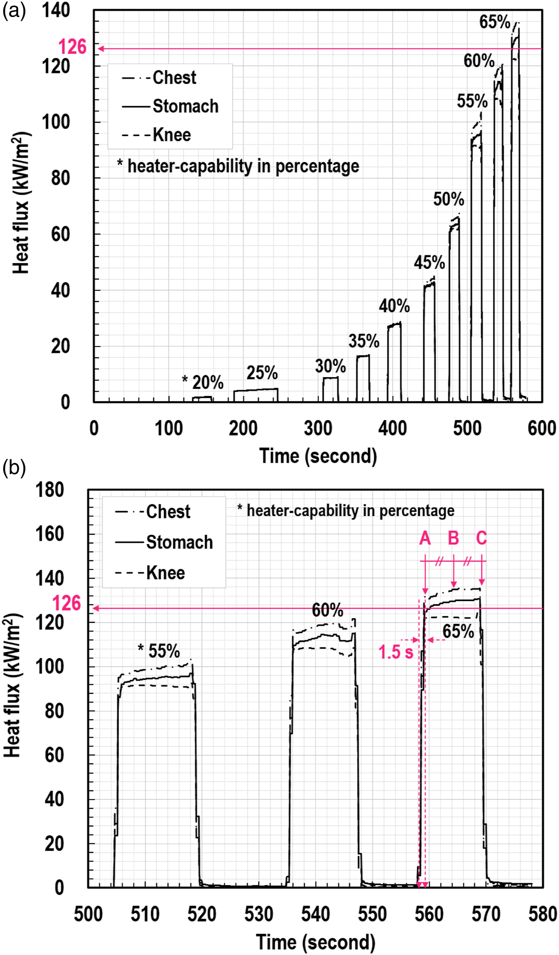
Findings from the validation are summarised as follows: 1. The intensity of 126 kW/m2 was obtained when regulating the heater-capability at around 65%; 2. Very rapid intensity increases were observed whenever activating the heater. Approximately 1.5 s were taken only to rise the intensity from 0 to 126 kW/m2, as described in Figure 10(b); 3. The consistency of heat emission for 12 s was satisfactory, as shown in the plateau regions of the profiles in Figure 10; the consistency refers to the difference between the intensities at the starting point of plateau region, A in Figure 10(b), and at its endpoint, C. An increase in the amount of intensity difference was observed with the rise of heater-capability, from 0.21 kW/m2 at 20%-capability to 9.09 kW/m2 at 65%-capability. However, the largest difference, 9.09 kW/m2, was 7.21% of the average value of the plateau region (i.e. 126.00 kW/m2); and 4. The intensity variation along the vertical direction from knee-to chest-position was acceptable; the variation indicates the intensity difference among the three profiles at the same instant (i.e. at A, B and C points) in the plateau regions of Figure 10. The vertical intensity variation increased with the rise of heater-capability, from 0.08 kW/m2 at 20%-capability to 9.73 kW/m2 at 65%-capability, at the midpoint (B). However, the largest difference, 9.73 kW/m2, was 7.68% of the average value of the plateau region (i.e. 126.72 kW/m2). This variation is related with naturally driven buoyant air-flow that was observed visually between the 2-m-height-heater and the probes. The flow caused by an air-temperature rise has an effect on the intensity variation along the vertically-configured heat flux metres that measure combined radiative and convective heat fluxes.
The features of emitting a highly intensive heat flux, instantly within 1.5 s, consistently for 12 s, and uniformly along the vertical direction can offer advantages for creating a suitable thermal environment to examine the thermal protective performance of the life-sized garment exposed to a critical thermal condition.
Uncertainty analysis on physical measurements shown in Figure 10.
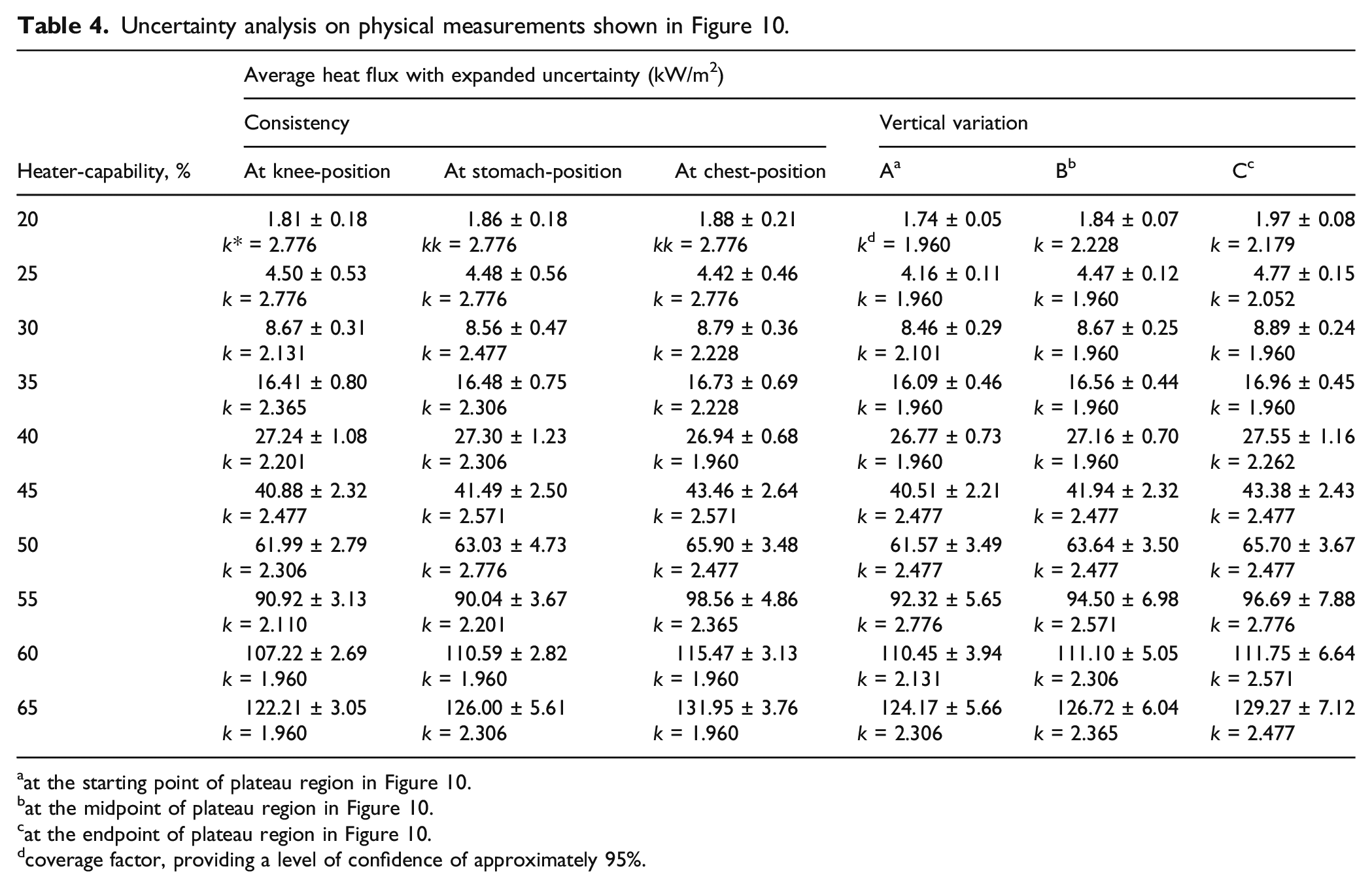
aat the starting point of plateau region in Figure 10.
bat the midpoint of plateau region in Figure 10.
cat the endpoint of plateau region in Figure 10.
dcoverage factor, providing a level of confidence of approximately 95%.
Validation of the in-house software
The analytical Finite Difference Method (FDM) skin model, encoded in the LabVIEW in-house software, were validated by using exiting literature.
24–26
Figure 11(a) shows time-temperature histories of the basal layer exposed to an intensity of 0.1 cal/(cm·s) for 34 s; the basal layer refers to the interface between the epidermis and dermis layers. The experimental data, reported by Stoll and Greene,
24
were obtained from the temperature measurement of blackened-skin surfaces and the corresponding temperature calculation at a depth of 80 μm below the surface, whereas the other predictions were calculated using a simple analytical conduction-model proposed by Hardee and Lee
25
and a numerical finite-element (FE) model derived by Torvi and Dale.
26
Overall, the proposed FD model showed good agreements with both the experimental and numerical profiles except the analytical prediction as this initial analytical model excluded several aspects such as three-layer structure, variable properties and blood perfusion. A comparison of the present model with prior studies: (a) time-temperature histories; and (b) differences among the data.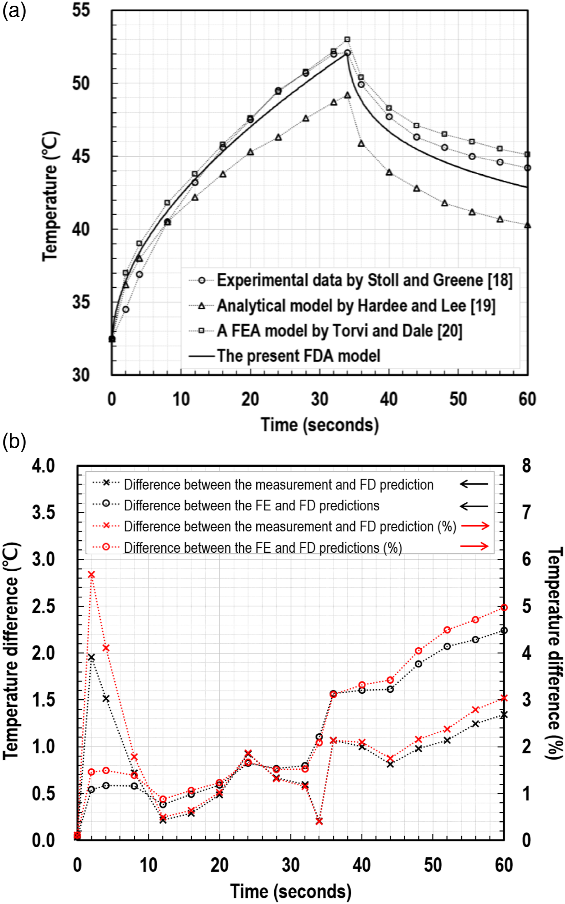
Figure 11(b) shows the differences amongst the data except the analytical prediction; the cross and round symbols refer to the discrepancies between the experimental measurement and FD calculation and those between the FE and FD predictions, respectively, while the black and red colours denote the values in temperature and percentage, respectively. In the initial transient-stage of the time-dependent profiles of the measurement and FD prediction, the largest difference was observed as 1.96°C, which is 5.68% of the experimental data. In the cooling stage of the FE and FD predictions (i.e. after 34 s), the difference was increased with time, up to 2.24°C in 60 s, which is 4.97% of the FE calculation. As a result, low differences were observed between the existing data and the present FD prediction.
Comparison between the data obtained from the full-scale and bench-scale apparatuses
For validation purposes, a preliminary test was conducted using the full-scale apparatus. The experiment was sequenced as follows: (1) Specimens are pre-conditioned at room temperature of 20 ± 4°C with relative humidity of 65 ± 2% in accordance with NFPA 1971
11
and BS EN ISO 6942
27
; (2) The fully dressed manikin is affixed on the rail trolley and stayed away from the heaters before the heater activation; (3) The specimen is physically moved on the rail toward a pre-planned position in the course of heaters’ stabilisation, as shown in Figure 12(a). In the interim, the thermal shields are closed not to cause any potential irradiance on the exposed surface of the specimen; (4) Once arrived, the shields open within 1.5 s, and the specimen is exposed to heat for 12 s, as shown in Figure 12(b); and (5) After 12-second-thermal-exposure, the shields are closed, and simultaneously the specimen is moved backward gently, not to be exposed to any residual heat. A comparison between the data obtained from the full-scale and bench-scale apparatuses: (a–b) the full-scale apparatus with a specimen; (c) the incident heat flux distribution through thermal manikin’s surface; (d) the time-heat flux profiles; and (e) the specimen structure in the bench-scale test.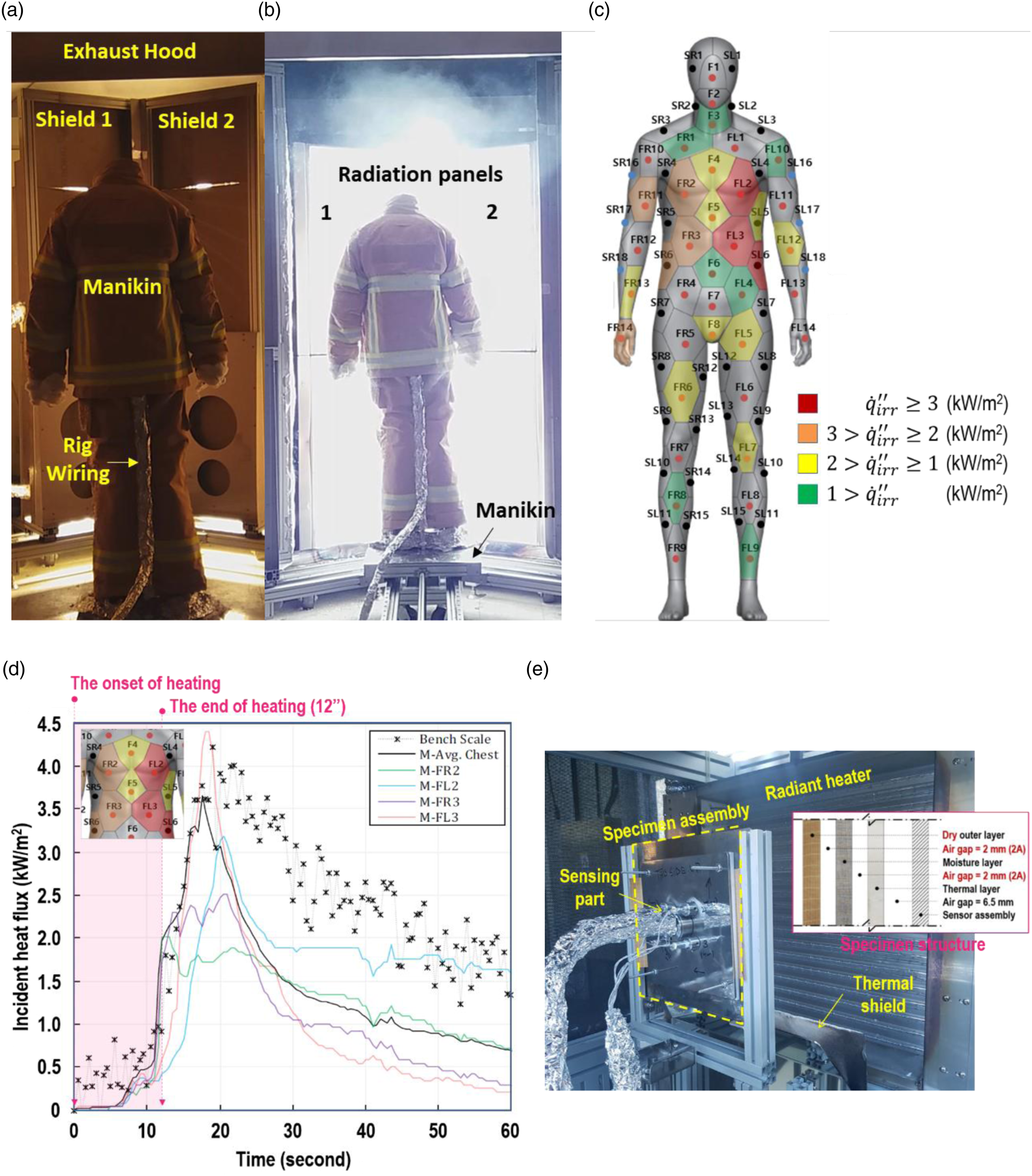
Figure 12(c) shows part of the measured data of the peak incident heat flux marked visually on the schematic of thermal manikin’s sensor mapping; the colours indicate the range of the amount of the incident heat flux on regions, as described in the legend. Overall, greater amounts of heat flux were transmitted across the three-layered clothing and incident on the regions of chest, abdomen and upper arm than those on the regions of lower body. This result is due to the body-curvature of the upright manikin causing the different horizontal distances from the heating elements to the regions, and to the clothing’s different design features on the regions, such as the degree of fit, air-gaps, seams, zippers and pockets.
The results from the full-scale experiment were compared with those obtained using a bench-scale instrument, 17 as shown in Figure 12(d); Solid lines indicate representative time-intensity profiles of four regions (i.e. FR2, FL2, FR3 and FL3 in Figure 12(c)), whereas cross marks with a dotted line denotes the data of the bench-scale test. A swatch specimen in the small-scale test was composed of three fabrics (i.e. outer, moisture and thermal layers) and spacers, as illustrated in Figure 12(e). It included 2-mm-air-gaps among the layers and a 6.5-mm-air-gap between the thermal layer and sensing assembly, whereas in the full-scale experiment air-gaps among the layers and between the thermal layer and manikin-shell were unmeasurable. In calibrations of both the apparatuses, the amounts of irradiance on the specimens were regulated at 126 kW/m2. Overall, the growing tendency of the averaged value (i.e. black solid line) towards the peak heat flux was in good agreement with that of the small-scale test profile. However, discrepancies were observed in the cooling stage beyond the peak moment. The disagreement is likely to be caused by the difference in the heat loss mechanism between the two apparatuses. As such disagreement will affect the degree of-burn calculation, further clarification on the relationship between the bench- and full-scale test results is needed.
Conclusions
The research project was initiated to create the 126-kW/m2-irradiance test environment to contribute to improving the survival chance of firefighters evacuating urgently from an unexpected growth of modern fires, through examining the behaviour of thermal protective clothing at highly intensive heat fluxes. Among several sub-topics, this paper discussed the practical development process of the full-scale test facility composed of the thermal chamber, radiant heaters, a thermal manikin with instrumented sensing assemblies, movable and shield equipment, and a DAQ system with the in-house software.
To operate the facility safely and sustainably, several implements were installed in the thermal chamber: the 3-phase AC-380-V/1,600-A electric power system with 2-step circuit breakers, 20-lpm-water-cooling system, ventilation-and-dust-collection system, semi-auto thermal shields and relevant devices. Both the thermal manikin and the sensing assemblies embed in the manikin-shell were custom-made to reflect the 50th percentile physique of 20–59-year Korean males on its size. The full-scale test system was controlled outside the thermal chamber by using the in-house software.
The goal of the intensity (i.e. 126 kW/m2) was achieved at around the 65%-capability in the system. To validate the heating system, several aspects were examined: the heating consistency for a specific time-period (i.e. 12 s); the intensity variation along the upright manikin height; and the rate of intensity-rise. Both the intensity-differences in respect of consistency and vertical variation were less than 10 kW/m2, which is approximately 7.9% of the target-intensity only, and the intensity increased up to the objective within 1.5 s. These features are advantageous for the garments’ thermal protective performance test that requires an extreme thermal exposure condition, greater than 84 kW/m2, for a limited period of time, less than 12 s. To validate the in-house software, the encoded model was compared with experiments proposed by previous works, resulting in low differences less than 3°C. The development process of the full-scale test facility can contribute to the enhancement of the thermal protective performance of garments and also be a reference to creating a critical radiant thermal condition for research purposes.
Footnotes
Declaration of conflicting interests
The author(s) declared no potential conflicts of interest with respect to the research, authorship, and/or publication of this article.
Funding
The author(s) disclosed receipt of the following financial support for the research, authorship, and/or publication of this article: This project is funded by NFA(National Fire Agency) and KEIT(Korea Evaluation Institute of Industrial Technology) through R&D programmes on Development of Fire Safety Technologies for ESS and Hydrogen Facilities (No.20011579) and for Emergency Response to Fire Hazards (No.20008021).
Appendix