
Abstract
Thermal protective clothing protects emergency responders from fire hazards. The thermal protective performance of the multi-layer fabric is standardly evaluated at the average value of a 1–3-cal/(cm2s)-intensity range. Considering the magnitude of modern fire events, the range’s upper limit (3 cal/(cm2s)) was proposed to take into account a critical radiation condition and a bench-scale apparatus, capable of creating the critical experimental environment, was developed in this study. This instrument includes a vertical configuration heater with an active water-cooling part, a vertical orientation specimen-assembly with a measuring part, a movable specimen-holder and thermal shields operated by pneumatic pumps, an exhaust hood connected to a pan, a data acquisition system, heating-power and mechanical equipment controllers and a computer with in-house burn-injury analysis software. A preliminary test was conducted to determine a specimen-assembly position that both optimised the heat-source power, heater-capability and apparatus-sustainability, and subsequently validated the uniformity and consistency of irradiance on the test sample. To conduct repeatable measurements, an in-house program was used to operate the heater, specimen assembly and thermal shields semi-automatically, in a sequence. The software includes an algorithm that allows one to analyse heat transfers across human-skin layers and to assess the degree of burn injuries. This paper outlines a comprehensive process of creating an experimental environment for samples that need to be exposed to a critical thermal condition.
Keywords
Introduction
Fire safety is one of the major issues in modern civilisation. In recent decades, researchers and engineers in this field have significantly advanced theoretical principles and practical applications, in terms of fire dynamics, material flammability, smoke and heat spread behaviours, egression and performance-based building design. This achievement would not have been obtained unless a comparison is made with experimental works. During testing, specimens are exposed to a prescribed elevated temperature. In order to create the designated fire environment, satisfying a specific testing scenario, it should consider several technical aspects, such as types of energy-sources and heating element, the amount of power supply, the thermal durability of the materials used for the apparatus, and the parts for cooling, measurement and data acquisition.
Much research in fire safety engineering has contributed to the improvement of the safety of emergency responders, as well as rescuees, against fire hazards. Figure 1 shows the number of firefighter casualties per 1000 fires in three countries. In the United States, the fluctuation of the numbers become stable at around seven casualties per year from 2005. In England, an increasing trend at the beginning of the 2000s reversed and became steady at around four casualties per year in the 2010s. The number in the Republic of Korea is two or more times greater than those of the USA and England in the 2010s. To improve the fire-hazard responders’ safety, Korean researchers have enhanced the thermal protective performance of a firefighter-garment and the method of its evaluation. Statistics for firefighter casualties per 1000 fire incidents.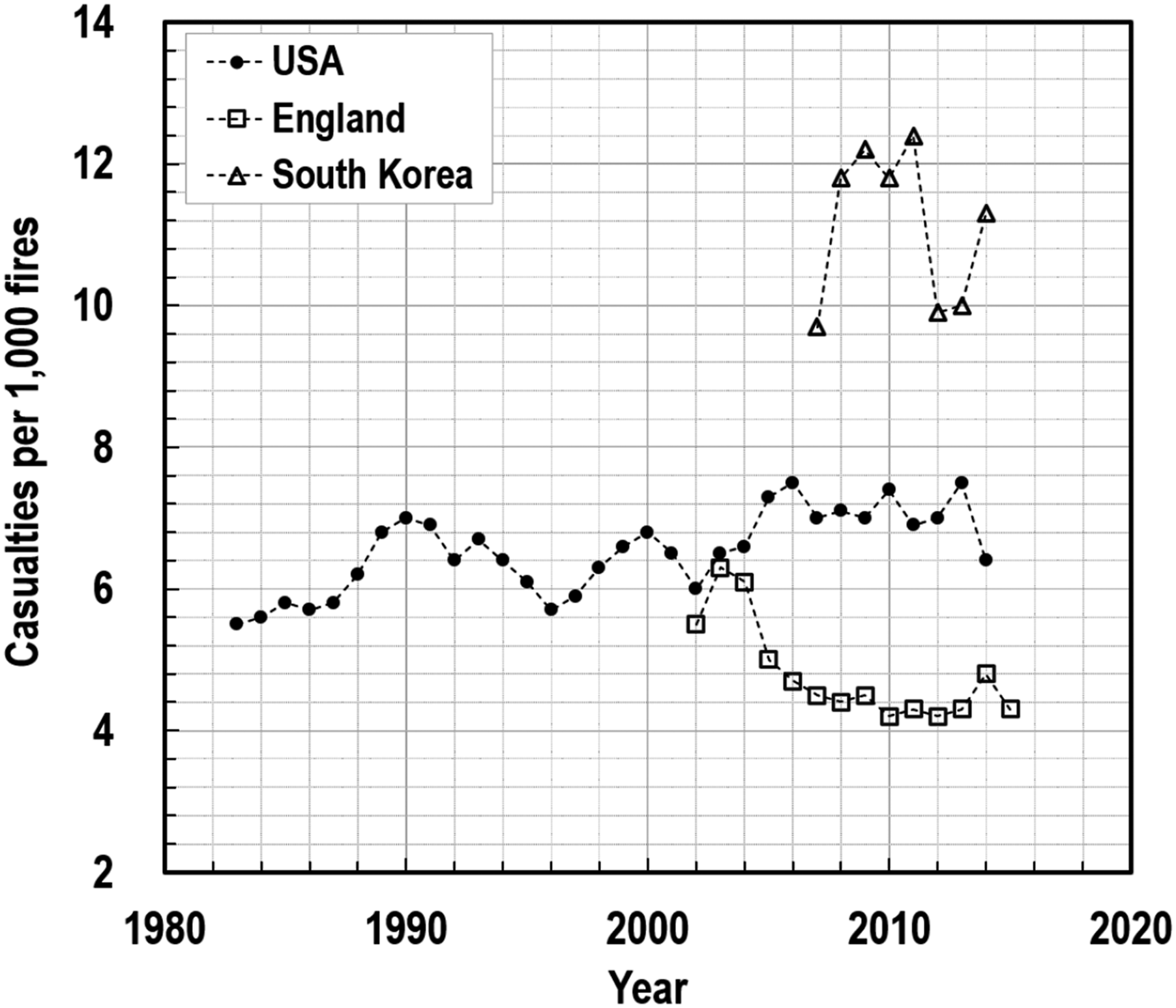
aFoster and Roberts. 1
bAbbott et.al. 2 ; and.
cColetta et.al. 3
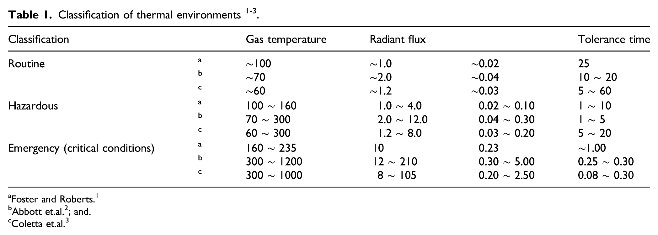
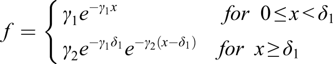
To establish a hazard level for thermal protective textiles based on TPP testing, Behnke employed the concept of a flash fire with an intensity quantified in a range of 1–3 cal/cm2s (41.9–125.6 kW/m2) through a series of laboratory-scale experiments in the 1970-80s 4,5 . In his studies, Nomex® III aramid fibres were heated at a constant heat flux of 2 cal/cm2s for various durations and subsequently the degraded appearances were visually inspected. These fabric-responses, corresponded to the total exposure energies calculated by multiplying the constant intensity by an exposure duration, were tabulated as an indicator of hazard intensities. Meanwhile, Nomex® garments damaged from flash fires had been collected for several years and also similar types of fabric that had been exposed at 2 cal/cm2s in laboratory-scale tests. The exposure times, required to duplicate the physical appearance of the damaged garments, were recorded to estimate both the total exposure energy and the energy transfer rate (heat flux), resulting in 4–19 cal/cm2 and 1–3 cal/cm2s, respectively. 4 Based on the empirical data, an average of the heat flux range (i.e. 2 cal/cm2s), that is discharged from 50%-radiant and 50%-convective heat sources, was proposed as the standard intensity representing flash fires, which is equivalent to approximately 84 kW/m2 in SI units. The use of the flash fire concept has been widely accepted as a criterion for fatal risks.
Flash fires, originating from hydrocarbon fires, have the key feature of extremely fast combustion, caused by the rapid consumption of the diffuse fuel-vapours in the air. This feature is also found in critical thermal conditions, created beyond the flashover phase of compartment fires, as shown in Figure 2(a). The maximum temperature and thermal density, observed during the post-flashover, are typically known as over approximately 1100°C and 150 kW/m2.
6–7
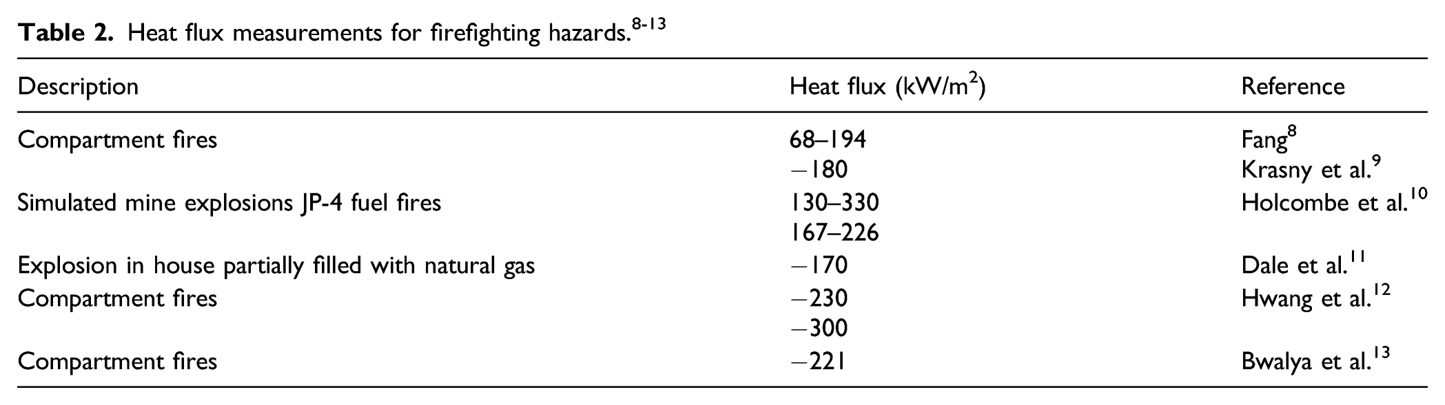
In this respect, Figure 2(b) and Table 2 show that the maximum heat flux data, obtained from compartment fires over the years in existing studies
8–13
, indicate fire events often exceeding far beyond the 84-kW/m2-value particularly under conditions where there is modern room furnishing. Further knowledge is certainly demanded on the thermal protective performance of firefighters’ garments when exposed to this worst-case compartment fire beyond 84 kW/m2. This intensity is referred to as a critical thermal condition in this study. Characteristics of compartment fires: (a) fire stages and the corresponding environments and (b) the maximum heat fluxes in compartment fires.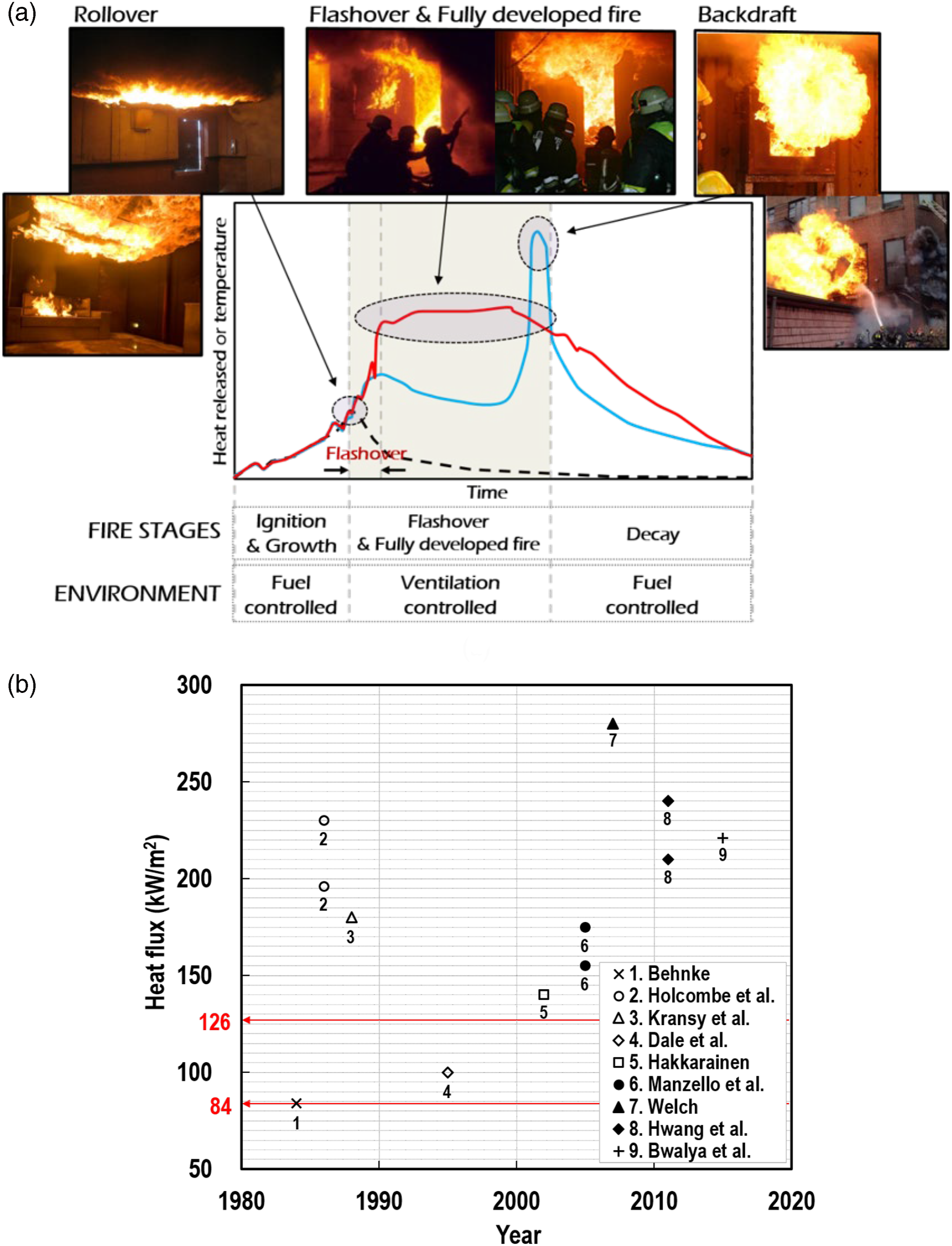
The critical thermal condition is more closely related to firefighters’ survival or fatality, rather than casualties. As an encounter with this condition occurs unexpectedly and quickly during fire suppression in a compartment, the thermal protective clothing should retard the heat transfer to the wearers skin, even for a short instant, to allow time to egress urgently from the place for survival. A tolerable distance limit from the hallway for survival was estimated as just 1.5 m based on the assumptions of 0.76-m/s-speed crawling and the maximum exposure time of 2 s. 14 Under the critical thermal condition, a very slim chance of survival would exist, when firefighters are engulfed by flames, because both the convective flame and the radiant heat will simultaneously damage the protective clothing and human skin. Compared to the former case, firefighters would have a relatively higher survivability, provided the encounter with the critical radiation condition excludes the situation of firefighters being engulfed or directly touched by flames. For firefighters, this radiation condition is more usual, more dominant at elevated temperatures, and less hazardous than the former case. In this context, it was decided that the latter was the worst-case scenario in which firefighters could have a small chance of survival at least, and it was proposed that this critical radiation condition needed to be at least the upper limit of the flash-fire intensity range (i.e. 126 kW/m2).
The aim of this research project was to develop a testing system to assess the thermal protective performance of garments under these critical thermal conditions. A series of technical issues were resolved as follows: (1) developing a bench-scale apparatus creating a radiant 126-kW/m2-heating-condition, (2) establishing an instrumented manikin with heat flux sensors, (3) organising a data acquisition network that records outputs measured from dozens of points, (4) architecting an in-house software that controls the testing system and has functions to analyse heat transfer across human skin layers and the degree of burn injuries and (5) developing a full-scale testing system. As part of the project, the first topic was comprehensively discussed in this paper, and the rest are presented in another companion article by Kang et al. 15 Before going to the primary topic, the features of the bench-scale apparatuses and evaluation methods, currently available in fire protective clothing engineering, and their limitations were reviewed in the next section, as a reference point for our apparatus-development. As a summary of this secondary subject, the existing standard bench-scale apparatuses are appropriate to rate the thermal protective performance of textile materials. However, they need more functions to be used to study several aspects affecting the performance, such as the level of the heat source, fabric configuration, air-gap thickness and moisture (or steam) content, which have been examined using customised instruments. 16–20 As one of these attempts, the apparatus proposed in this study was devised to impose a radiant 126-kW/m2-heating-condition on the specimen-surface for a specified time-period as consistently, uniformly and stably as possible. This testing environment was therefore designed to provide information on the thermal boundaries of the subjected specimen to be used for further studies on heat-and-mass-transfer across textile layers and air gaps. The algorithm of burn injury degrees was also linked to the test data for comprehensive discussions. Subsequently, the primary topic (i.e. the apparatus-development) was investigated with respect to the development process of (1) a heating part including the heat-source type, heat transfer mechanism from heater to specimen, and irradiance distributions throughout the sample’s exposed surface; (2) a specimen assembly with a sensing part; and (3) relevant devices. The reliability of the heating environment was also studied in the discussion section.
The features and limitations of the current apparatuses
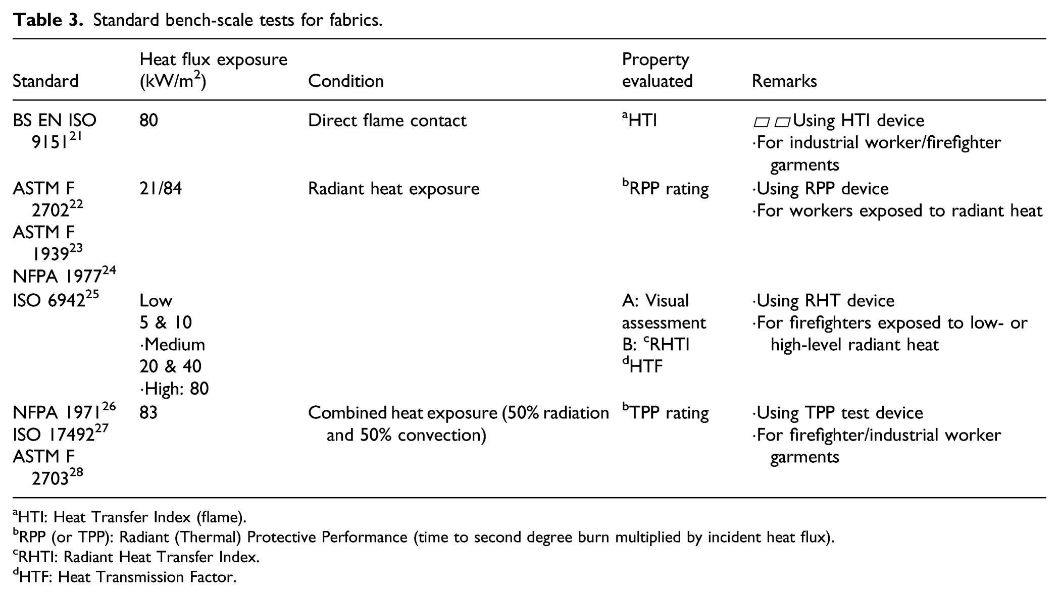
Several types of bench-scale apparatus exist, designed to assess thermal protection performance of clothing, as shown in Figure 3 and Table 3. Four major standard testers are (1) a heat transmission index (HTI) tester, (2) a radiant heat transfer (RHT) tester, (3) a radiant protective performance (RPP) tester and (4) a TPP tester, in accordance with BS EN ISO 9151,
21
BS EN ISO 6942,
25
ASTM F 2702-15,
22
and NFPA 1971,
26
respectively. Standard bench-scale tests for fabrics.
aHTI: Heat Transfer Index (flame).
bRPP (or TPP): Radiant (Thermal) Protective Performance (time to second degree burn multiplied by incident heat flux).
cRHTI: Radiant Heat Transfer Index.
dHTF: Heat Transmission Factor.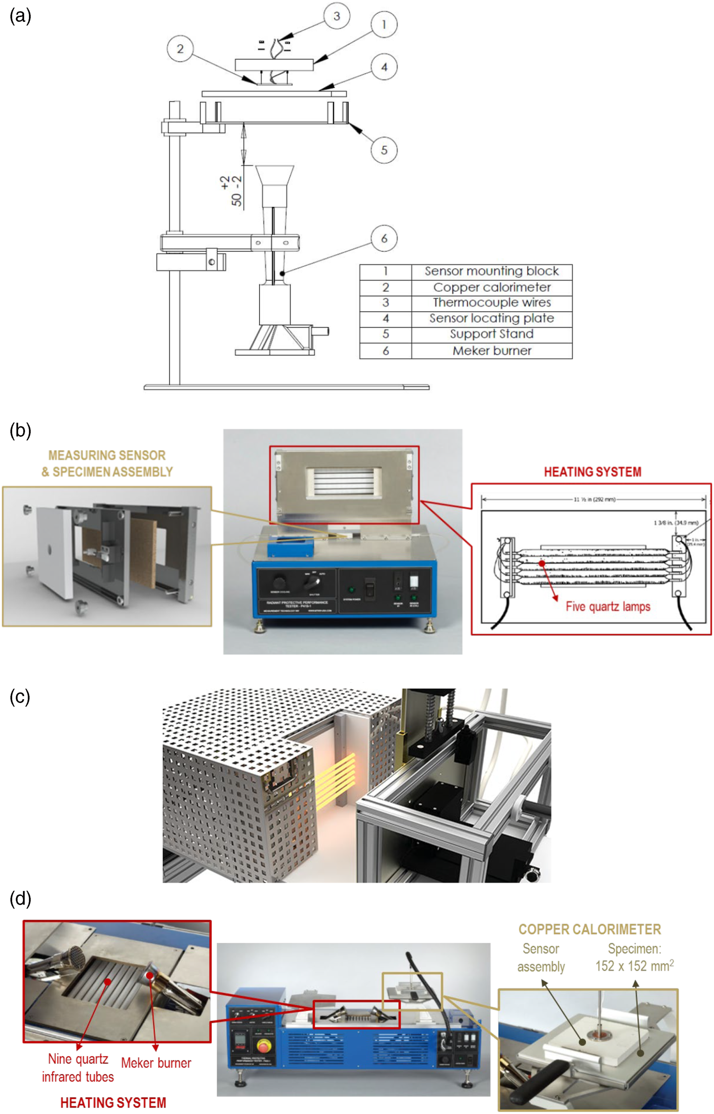
The first HTI tester is developed to rank textile materials with a heat transfer index indicating the relative heat, originating from a gas burner, transmitted across the sample and arriving at a small copper calorimeter, as described in Figure 3(a); the index is calculated from the mean time in seconds when achieving a temperature-rise of 24°C using the calorimeter. A propane-fuelled Meker burner with a 38-mm diameter is configured 50 mm underneath the specimen-sensor assembly and emits an incident heat flux of 80 kW/m2 ± 5% on the horizontally oriented specimen with a 50 × 50-mm exposed surface.
The second RPP tester is used to evaluate thermal protective characteristics of textiles exposed to standardised radiant heats and is composed of a vertically oriented radiant heating part, a specimen assembly, and a copper calorimeter with a data acquisition system, as shown in Figure 3(b). Five infrared quartz lamps (500 W) are mounted and centred on a high temperature insulating board. The heating part enables a specimen to be subjected to two standard sets of radiant heat flux (21 and 84 kW/m2). The specimen assembly comprises of 292 × 85.7-mm front and rear holder-plates with a 64 × 152-mm central cut-out. A fabric sample is sandwiched between the two plates. In the sensor assembly, a 40-mm-diameter circular copper slug calorimeter with a single j- or k-type thermocouple wire bead is affixed to an insulation board. The sensor assembly is held through a bracket in the rear holder plate. In the same manner as in the evaluation stage in TPP testing, the amount of the total heat is calculated and used in the assessment of fabrics’ thermal protective performance.
Another radiant heat tester (i.e. RHT) is aimed to create a wide range of radiant exposure conditions and employs six silicon carbide (SiC) heating rods with 178-mm-length and 7.9-mm-diameter as a radiation source, as shown in Figure 3(c). A test sample has dimensions of 230 × 80 mm and is configured vertically by a specimen holder, parallel to the heating part. A copper plate calorimeter curved into an arc with a radius of 130 mm is also mounted into the holder. Specimens are exposed to the following levels of radiant intensities: 5 and 10 kW/m2, 20 and 40 kW/m2, and 80 kW/m2 for low-, medium- and high-level conditions, respectively.
The last TPP tester is designed to subject a fabric sample to a nominal constant heat source, in order for commercial products to be classified, and comprises of a specimen assembly, a thermal source and a sensor assembly with a data acquisition system, as shown in Figure 3(a). A 150 × 150-mm fabric sample is held in place by an upper and a lower mounting plate. Square holes with dimensions of 133.4 × 133.4 mm and 102 × 102 mm are centred in the upper and lower plates, respectively. This specimen assembly is exposed to two types of heat source: two Meker (or Fisher) burners which are affixed underneath the specimen at a nominal 45-degree angle from the vertical, and nine quartz infrared tubes which are also affixed beneath and but centred on the sample. These heating elements simulate convective and radiative thermal hazards, respectively. The thermal exposure condition for the specimen is set as 50/50 ± 5% radiant/convective balance of the total heat source of 83 ± 4 kW/m2. The incident heat flux on the exposed sample surface is transferred throughout the thickness of the fabric specimen and reaches a copper calorimeter. The 40-mm-diameter calorimeter is coated with flat black paint and is surrounded by an insulation board. The sensor assembly is fitted into a square hole in the upper mounting plate (133.4 × 133.4 mm), and is in contact with the surface of the fabric. The total heat flux arriving at the calorimeter is calculated from the output of calorimeter’s thermocouples using a measured temperature rise and the thermal capacity of the copper. The heat flux data obtained are multiplied by the exposure time to calculate the quantity of the total heat (in kJ/m2). The quantity is used to assess the thermal protective performance of the given fabric. In the evaluation stage, the total heat data regarding human tissue tolerance to second-degree burn are directly used as the criteria of performance.
Additionally, a vertical orientation fabric tester is developed by the National Institute of Standards and Technology (NIST)
29
to assess the clothing’s thermal protective performance over a wide range of environmental conditions and extended time periods, capable of providing low to moderate heat flux exposures ranging from about 1.5 kW/m2 to more than 50 kW/m2. The instrument is composed of a premixed air/natural gas fuelled radiant panel with a propane gas pilot line and a specimen assembly on a trolley, as shown in Figure 4(a). The radiant panel originates from ASTM E162-16
30
and is generally operated at an average surface temperature of 670 ± 4 C. The pilot flame is designed for direct flame contact. The specimen assembly is composed of a 305 × 305-mm fabric sample and a 255 × 255-mm holder, as shown in Figure 4(b). The rear of the specimen assembly is either open to observe physical changes or closed to prevent heat loss. This testing setup allows to examine the thermal performance of surface features, such as trim, pads, patches or pockets. Configuration of the fabric tester developed by NIST
29
: (a) components and (b) specifications of specimen assembly.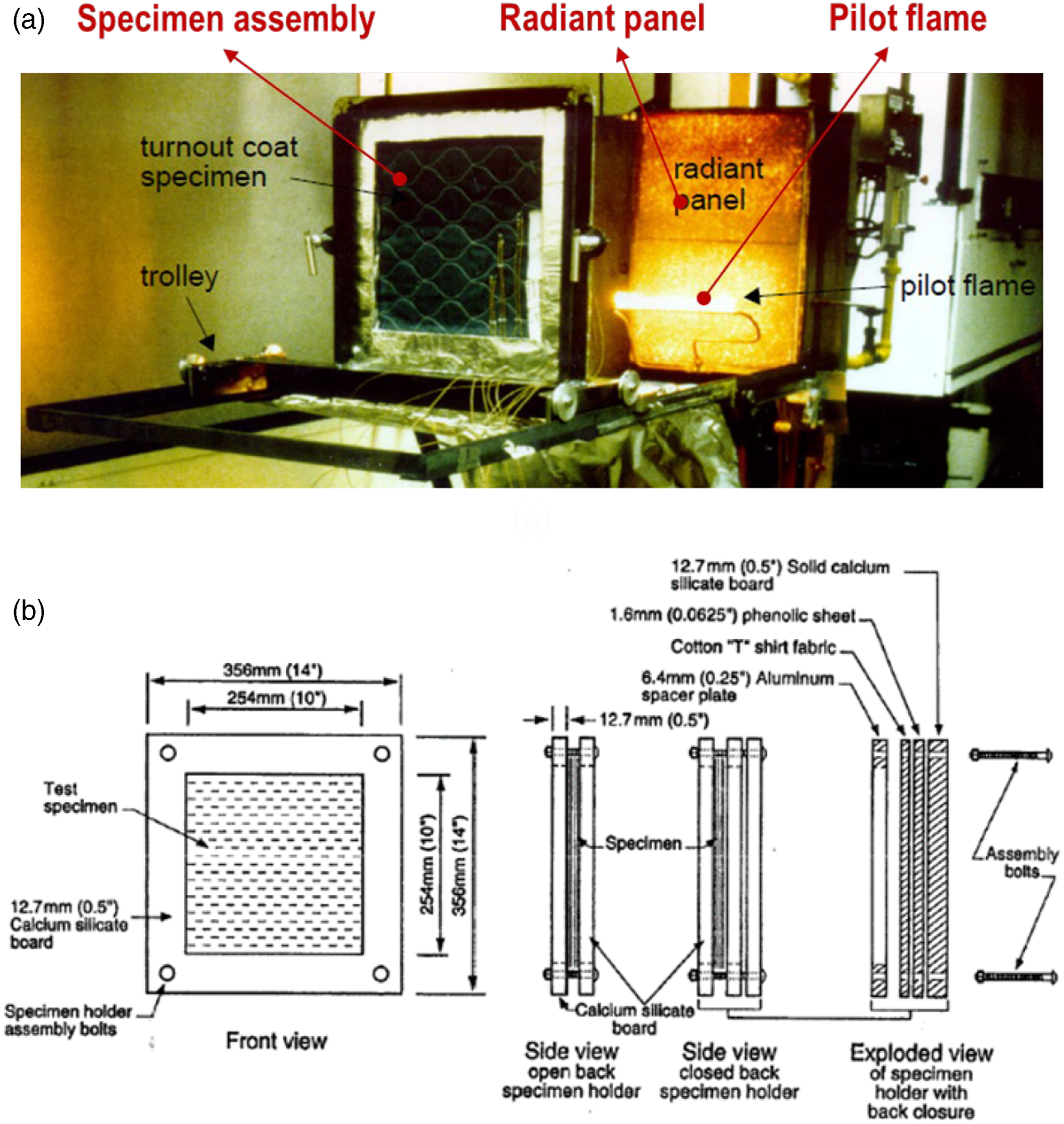
The aforementioned four standard testing devices were originally designed to rate the performance of textile materials with rating indexes, such as HTI, RPP (or TPP), RHTI and HTF, rather than to measure a specific value indicating the true protection offered by fabrics 31 and to examine the characteristics of fabrics subjected to a specified heat exposure; the rating indexes do not include any scientific meaning adaptable for further parametric studies on heat-and-mass-transfer across fabric layers and air gaps. To cover their limitations for research purposes, attempts have been made to customise the existing apparatuses to examine several aspects, such as the level of the heat source, 17 fabric configuration, 18 air-gap thickness 16–18 and moisture (or steam) content, 20 since these aspects are acknowledged to have effects on the thermal performance of fabrics. To study the effects, care should be taken in clarifying the thermal boundary condition of the specimen subjected to the instruments. To achieve the clarification, the sample should be exposed to well-controlled heat assaults for a specified short period of time as consistently, uniformly, and stably as possible. In this context, from an apparatus-development viewpoint, electrical heaters can provide more favourable conditions for the test sample than diffusion flames or gas-fuelled radiant panels, particularly at highly intensive heat fluxes, and among electrical heaters a halogen quartz lamp is advantageous to the SiC heating rod due to the ability to increase and decrease its temperature instantly and to maintain it consistently. In addition, for comprehensive analyses, an apparatus should be capable of customising testing conditions, such as the air-gap thickness, irradiance-level and exposure-scenario, and its thermal data need to be systematically led to the algorithm of burn-injury degrees, which is not yet supported by the existing instruments.
Development of an advanced bench-scale apparatus
General
A bench-scale instrument was developed to evaluate the performance of the three-layered fabrics applied for a firefighters thermal protective clothing, particularly at the critical intensity of 126 kW/m2. This testing system was composed of a vertically oriented heater, an active water-cooling part, a vertically oriented specimen assembly with a measuring part, a movable sample-holder and thermal shields with pneumatic pumps, an exhaust hood with a pan, a data acquisition system, heating-power and mechanical equipment controllers and a computer with an in-house burn-injury-analysis software, as shown in Figure 5(a). Figure 5(b) shows the final version of the apparatus. Configuration of the bench-scale apparatus: (a) a schematic diagram and (b) the final version.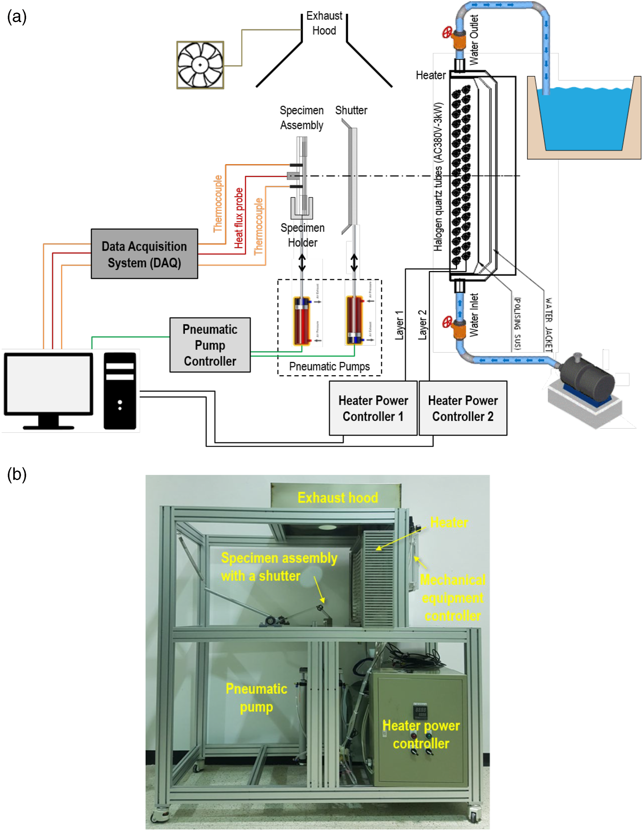
Heat source
As the firefighters’ safety during suppressing fires is the priority, approaching hot diffusion flame and smoke plumes is not recommended in the operating principle so that firefighters are usually exposed to radiant heat rather than convective gases, particularly under critical thermal conditions. In addition, thermal radiation is the dominant heat transfer mode in the extreme conditions originating from high-temperature plumes mixed with flame, gas and soot. Several types of heating elements capable of simulating a radiant heating condition exist, such as flames, gas-fired panels, electric resistance heaters and high-temperature lamps 32 Among the types, this model adapts high-temperature quartz tube lamps, capable of emitting irradiances beyond 126 kW/m2 on the exposed surface of fabric samples.
Heating part
Lamp filaments typically operate up to nearly 3000 K for a short period of time, and produce a large amount of radiant energy, which is a function of the fourth power of the elements’ absolute temperature based on the Stefan–Boltzmann’s law. In addition, tiny quantities of a halogen filled quartz tube prevent the evaporated atoms from the tungsten coil from being deposited on the inner surface of the envelope’s glass, due to the formation of halogenides and the production of halogen-cycle reaction. This feature leads to maintaining the clarity of the glass, resulting in the provision of a constant prescribed heat flux to a specimen.
To uniformly/consistently impose the desired irradiance of 126 kW/m2 throughout a 100 × 100-mm exposed surface of the specimen, three aspects should be determined: (1) a total heat-source power (kW), (2) a geometrical relationship between the heater’s heating area and the specimen’s receiving area and (3) a practical percentage of the maximum heater-capability. The amount of heat-source power is typically in a linear proportional relationship to the number of lamps; however, this number is not directly proportional to the quantity of heat reaching the test sample due to the heater-specimen spatial relationship, which is represented by a view factor. The larger the practical percentage, the greater the heat is emitted; however, increasing the percentage up to the heater’s tolerance limit (100%) could damage the apparatus and causes mechanical failures.
To optimise the relationships among the aspects, preliminary tests were conducted using a pilot instrumental model with a calibrated Schmidt–Boelter gauge, as shown in Figure 6(a). The heat transfer mechanism from the heater to specimen assembly were defined, as shown in Figure 6(b), as follows Schematics of the heater structure: (a) preliminary test plan and (b) heat transfer mechanism.
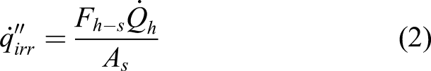

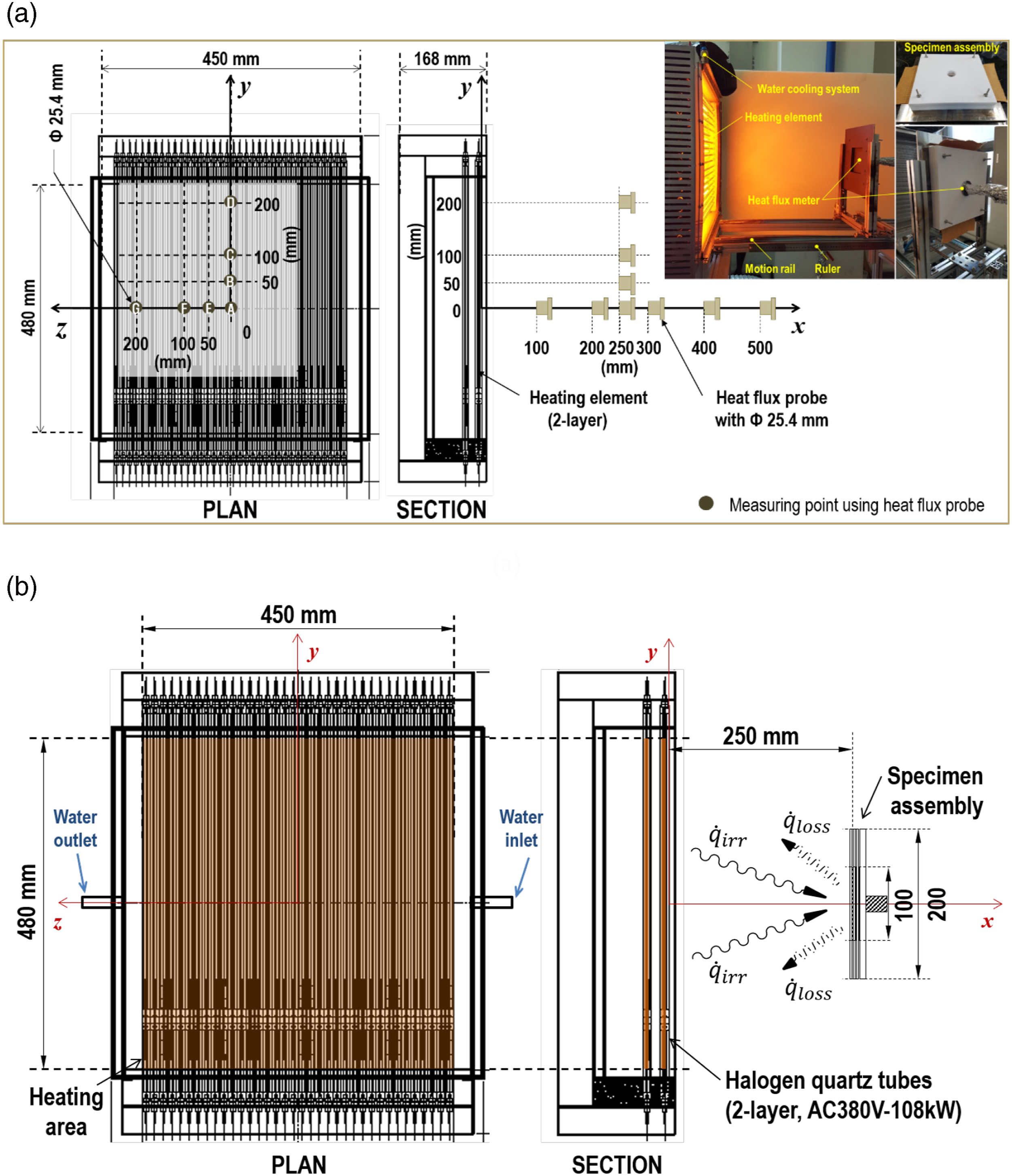
The subscripts h and s refer to a heater and a specimen, respectively.
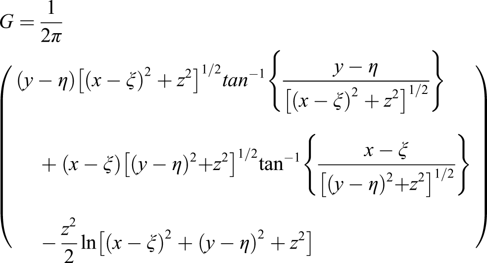
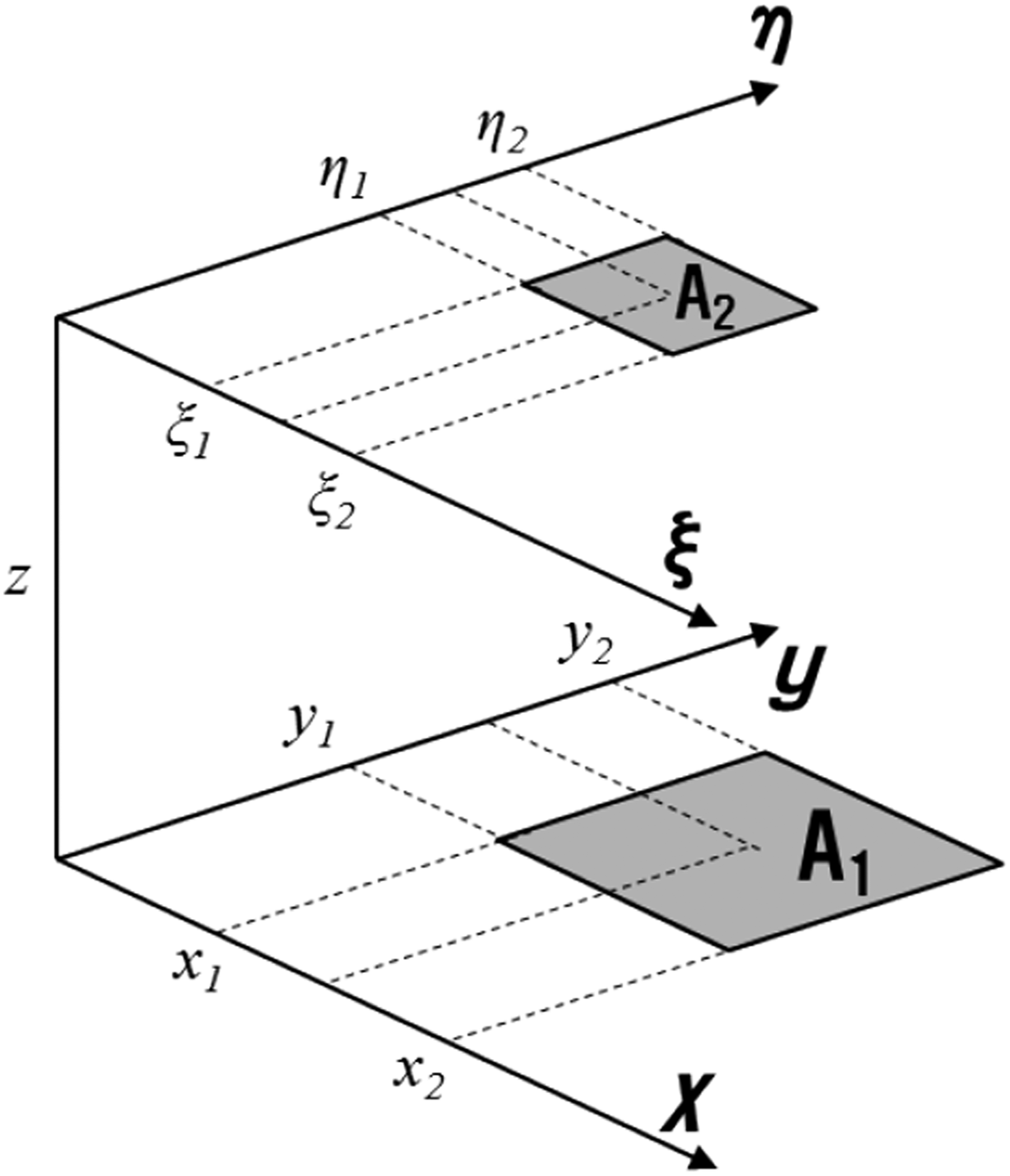
The heat flux variation over the change in the distance between measuring points from the heater centre was measured to determine the specimen-assembly position in a local Cartesian coordinate system with x-, y- and z-axes, as shown in Figure 6(a). To verify the physical measurement, configuration factor algebra for two parallel finite rectangles, shown in Figure 7, was employed by using the equation below
33
Geometrical relationship between two parallel areas.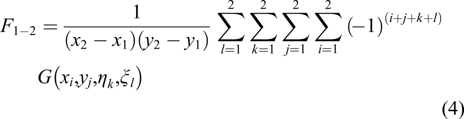
Experimental heat flux variations along the x-direction were verified by analytical predictions, as shown in Figure 8. Black and red dotted lines refer to measurements and predictions, respectively. Since all the measurements were quintuplicated at each of the positions, the upper and lower bars and the middle mark indicate the maximum, the minimum and the mean values, respectively. The experimental profile was in good agreement with the prediction. Notably, a remarkable decrease in the heat flux quantity was observed with the horizontal distance increase from the heating area. The irradiance variation along the horizontal distance between the heater and specimen in the x-direction obtained from the preliminary tests.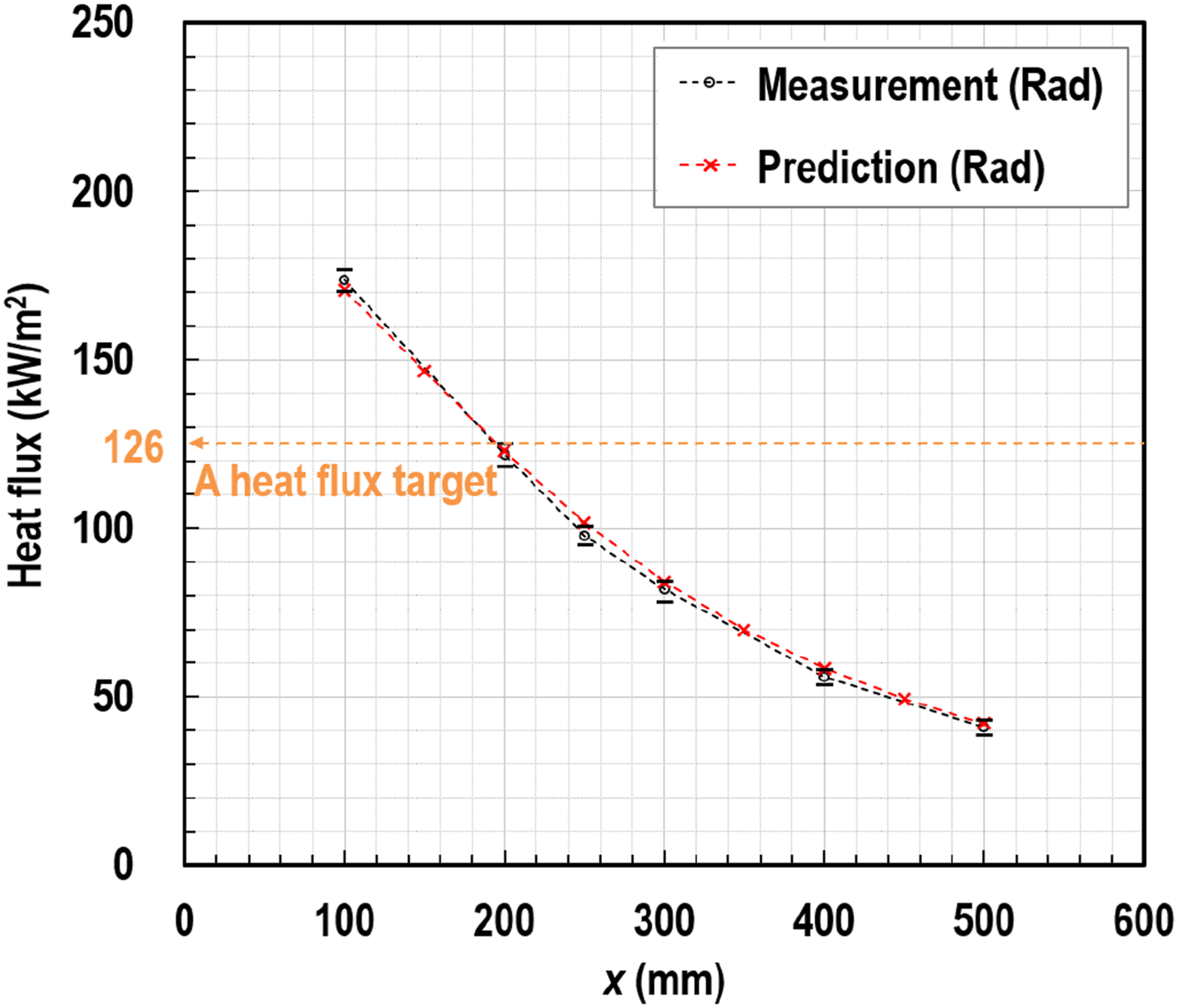
As a result, to allow the specimen’s exposed surface to receive the desired irradiance of 126 kW/m2, the three aspects (i.e. heat-source power, geometric relation and heater-capability) were optimised as follows: (1) the heater consists of 36 infrared halogen tubular quartz lamps (AC 380 V/108 kW in total) arranged in two layers to increase thermal density, as shown in Figure 6(b); (2) the specimen’s exposed surface was distanced 250 mm from the heater; and (3) the heater-capability was set as approximately 76% of the total allowable electric power. Electric power providing 3-phase AC 380 V/164 A was required at least to operate the instrument. An inflow of tap water with a flow rate of the order of 12 L/min and an inlet temperature below 22 C were set to prevent any fractures of electrical parts, heating elements and the stainless-steel structure from being over-heated. It is noted that since the level of heater-capability for emitting the 126 kW/m2-irradiance slightly varied up to ± 2% according to environmental conditions, such as room temperature and humidity, it is required to perform calibration to set the level per day before the main testing. Care should be taken to maintain low heater temperature with the following values, an inflow-water of flow rate faster than 12 L/min, and temperature lower than 22 C, in order both to impose a consistent irradiance on the specimen and to confirm the durability of the heater.
Specimen assembly with sensing part
A specimen assembly was composed of a fabric sample (outer, moisture and thermal layers), a holder plate, polytetrafluoroethylene (PTFE) spacers and a sensing part, as shown in Figure 9. The sizes of the air gaps between the three layers and the gap between the thermal liner and sensor were regulated by use of PTFE spacers of different thicknesses. The fabric layers were clenched in tension, which secures the predetermined size of the air gaps. This setup allows the natural convection generation within the gaps as would typically occur in the gaps of a garment exposed to heat. The outer shell’s area exposed to the heater was determined as 100 × 100 mm based on a study on heat flux distributions throughout the exposed area, which is examined in the section of discussion. Section of specimen assembly with sensing part.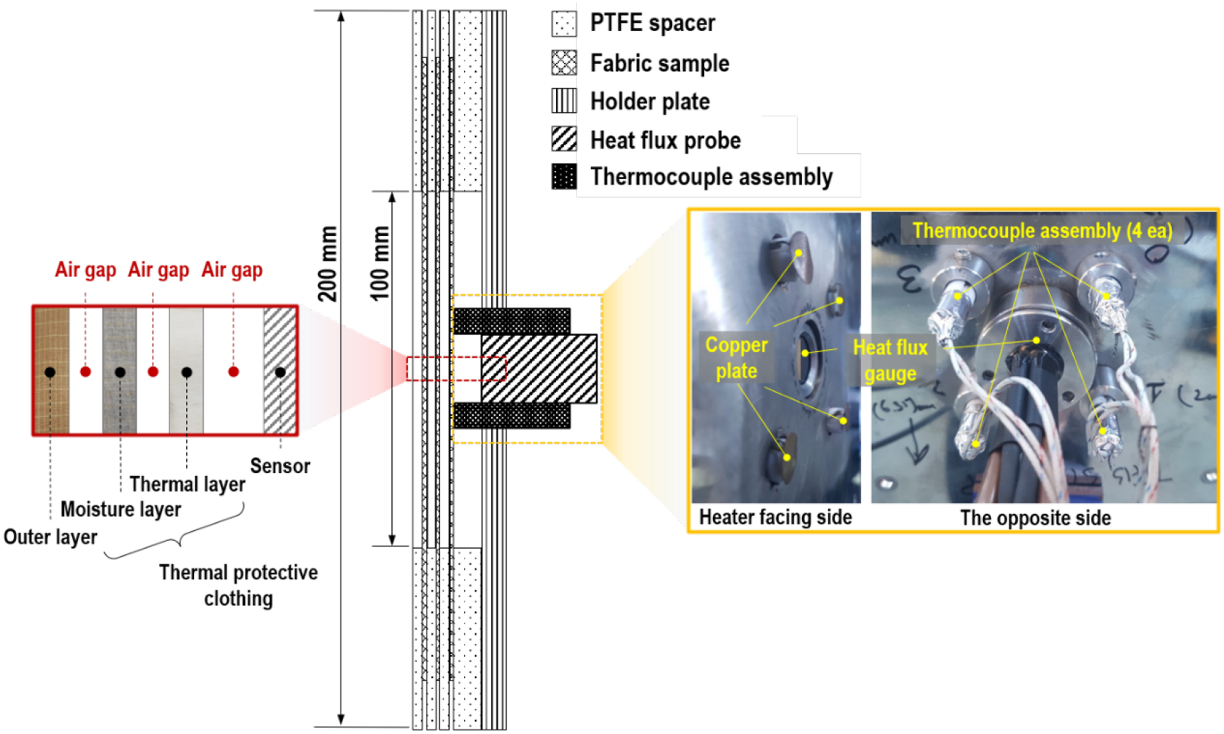
Several types of thermal sensing devices have been developed to be employed in the evaluation of a fabrics’ thermal protective performance. In general, for skin burn damage assessment purposes, materials with thermal inertia similar to that of human skin were adopted for sensors (i.e. embedded sensor by DuPont® and skin simulant sensor by University of Alberta), whereas, for direct heat flux measurement purposes, calorimeter-type, thermocouple-type (i.e. TPP sensor and PyroCal by NCSU) and water cooled sensors were used 34–35 . As the apparatus discussed in this paper was designed to emit a wide range of heat fluxes, up to a highly intensive heat (i.e. 126 kW/m2), for research purposes, care was taken to confirm the durability and repeatability of the system, so that a water-cooled sensor (Dual Captherm made by Captec Enterprise, sensitivity = 1 mV/(W/cm2), measurement range = up to 200 kW/m2) that is suitable for high-intensive and long-duration thermal exposures was selected, as shown in Figure 9; to check its limitation which is relatively slower response time than the copper slug calorimeters, four thermocouple-type calorimeters (t-type thermocouples welded onto copper plates, i.e. thermocouple assembly) were setup.
The net heat that is emitted by the heating element, transmitted across the fabric layers and air gaps and arriving at the exposed surface of the sensing part (i.e. 
The net heat measured 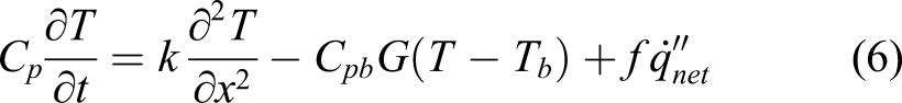

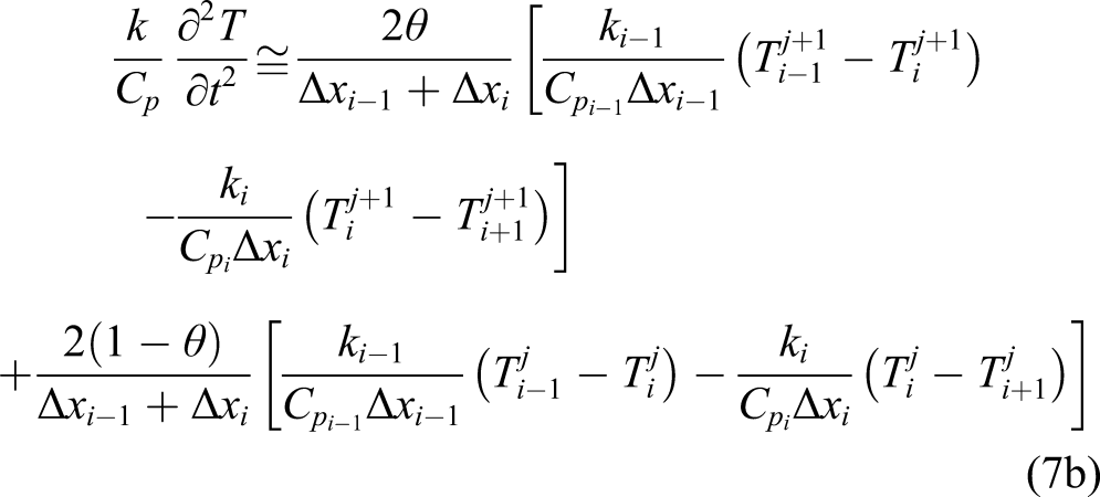
To solve the linear parabolic partial-differential equation, finite-divided differences were substituted for the partial derivatives, as below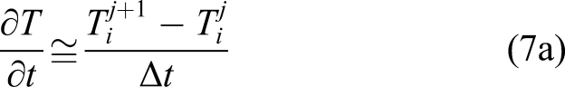
Both the models were encoded in a LabVIEW-based in-house software, as shown in Figure 10. An in-house burn injury analysis software based on LabVIEW.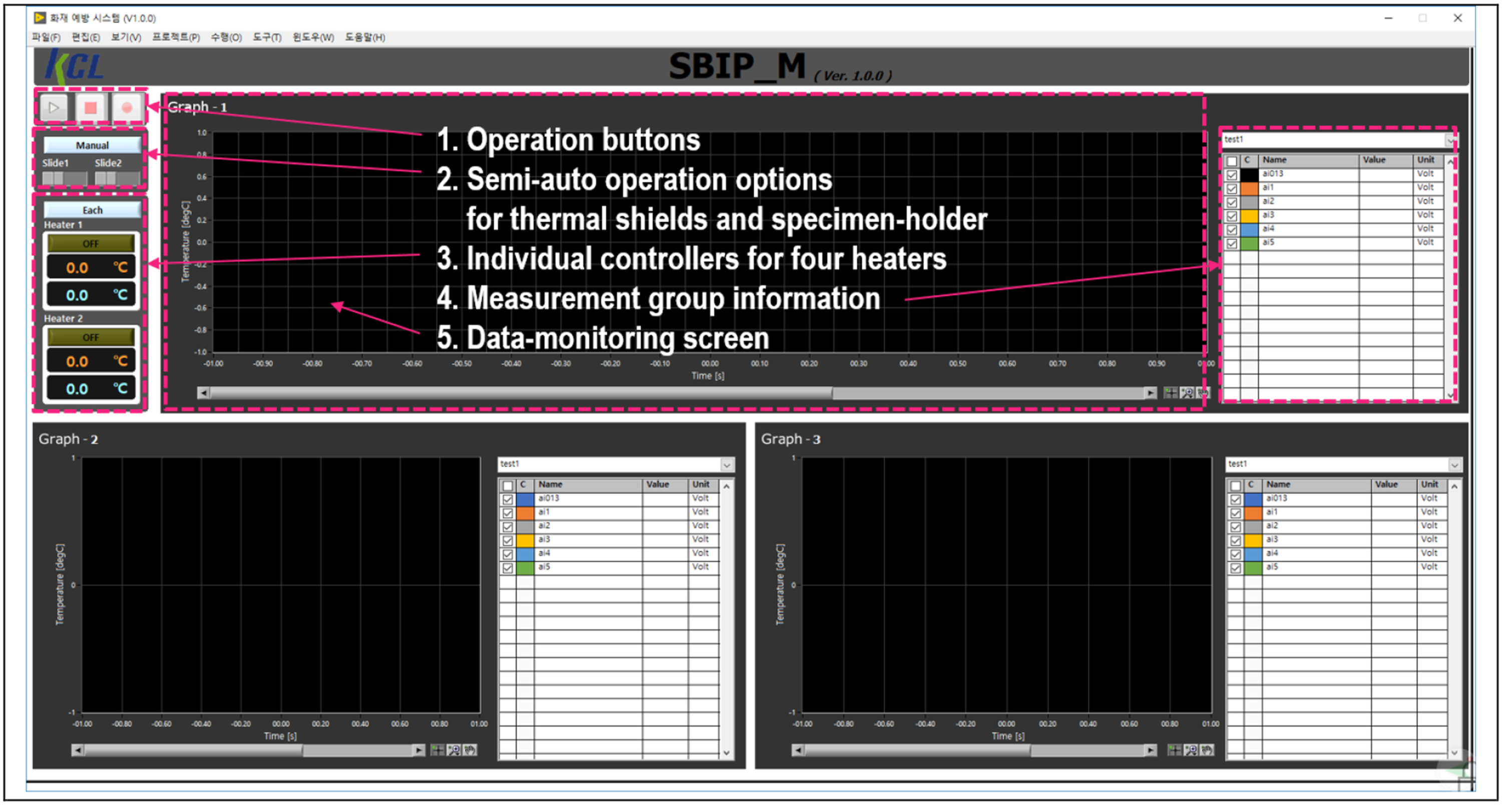
To secure the repeatability of testing and optimise the apparatus operation, a LabVIEW-based specimen-motion system was designed. This system managed two motions of a specimen assembly and a thermal shield individually. Since it took in the order of three or 4 min for the activated heater to emit a consistent quantity of radiation, during test preparation the specimen assembly was protected from the surplus heat by being lowered under the heat source and being covered by the shield, as shown in Figure 5(b). Two pneumatic pumps actuated individually the specimen assembly and thermal shield according to a sequence as shown Figure 11. It is noted that from the research viewpoint the specimen protection from undesigned heat before and after the predetermined thermal exposure (i.e. around 12 s) secured the accuracy and repeatability of testing, particularly at highly intensive heat fluxes. Sequential motions of specimen assembly and thermal shields during testing: (a) activation and stabilisation, (b) getting started, (c) heating and (d) the end of the test.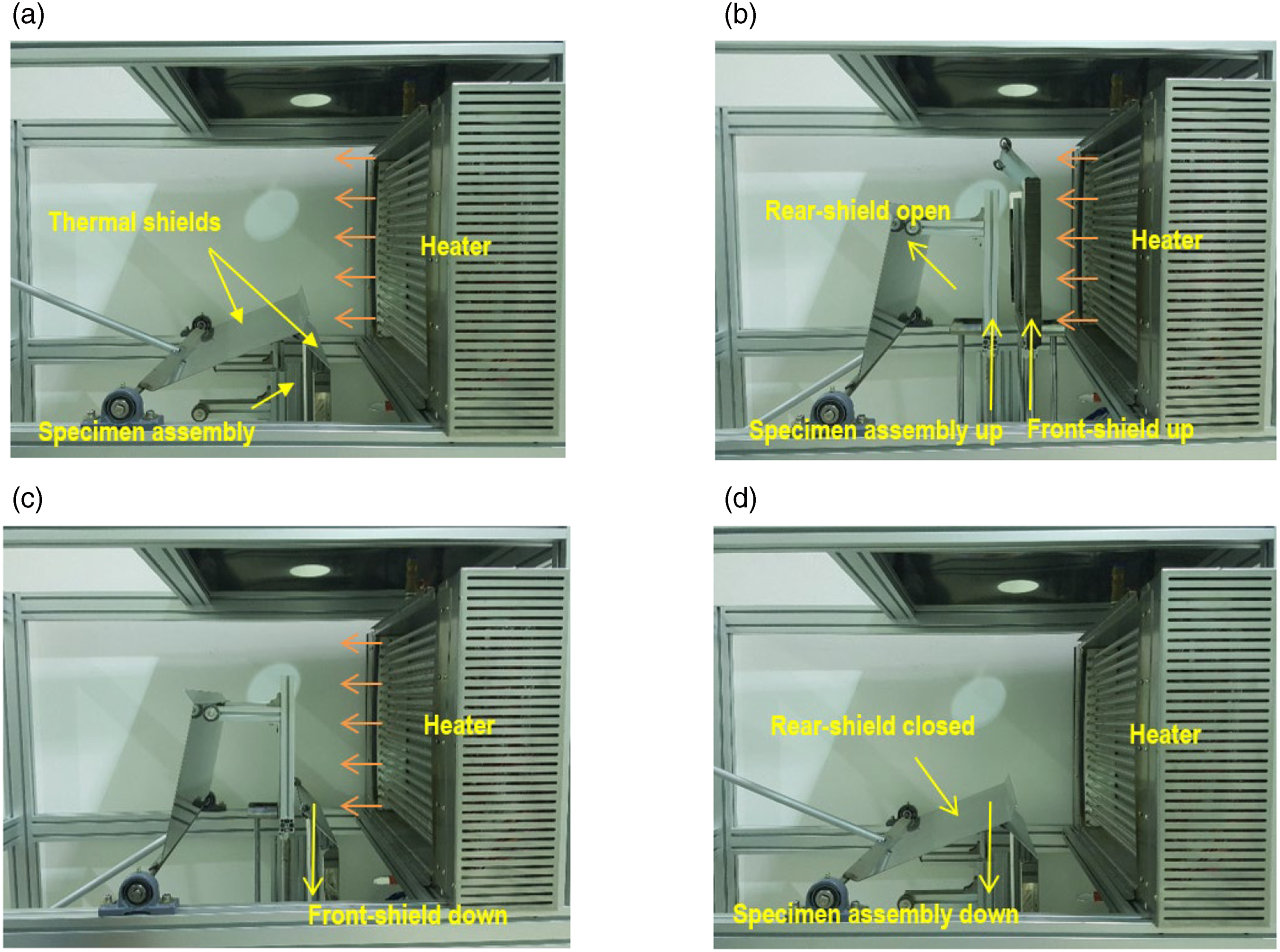
Results and discussion
Reliability of heating environment
To confirm the developed heating condition, three aspects were further examined in a series of measurements using a heat flux dual-transducer at different positions (i.e. A-G positions) specified in Figure 6(a): (1) the heat flux variation according to the horizontal distance from the heater to; (2) the heat flux uniformity throughout; and (3) the heat flux consistency on the 100 × 100 mm exposed surface of the specimen. Subsequently, the measurement obtained from the present heating condition was verified by the existing data from the previous studies 29,38,39
Figure 12(a) shows experimental and analytical heat flux variations as a function of the distance, with the estimate of the individual contributions of radiant and convective modes to the total heat flux; the black and blue colours of lines and marks indicate the measurement data, whereas the red colour denotes the analytical prediction of irradiance; the black dotted lines with the black-filled circle, empty-circle and empty-rhombus marks in the inset legend to Figure 12(a) indicate the total, radiant and convective heats calculated using equation (5), respectively. Overall, the thermal energy reaching A positions (y = 0 and z = 0 mm) significantly decreased with the distance increase. The heat arriving at x = 100 mm was reduced by up to 75.7% when the distance increased to 500 mm. This indicates that the closer the specimen is to the heater, the less power the heater requires to allow the sample to receive the irradiance of 126 kW/m2 and the less probability of failure the heater has. In terms of the individual contributions of radiation and convection modes, the radiation accounted for the range of approximately 75.1–77.1% of the total thermal energy transmitted over the distance range of 100–500 mm. This shows that radiation was the dominant mode in the electric lamp heating environment. Experimental and analytical results: (a) heat flux variations along the x-direction, (b) heat flux uniformity along the y-direction, (c) heat flux uniformity along the z-direction and (d) heat flux consistency at different heating conditions.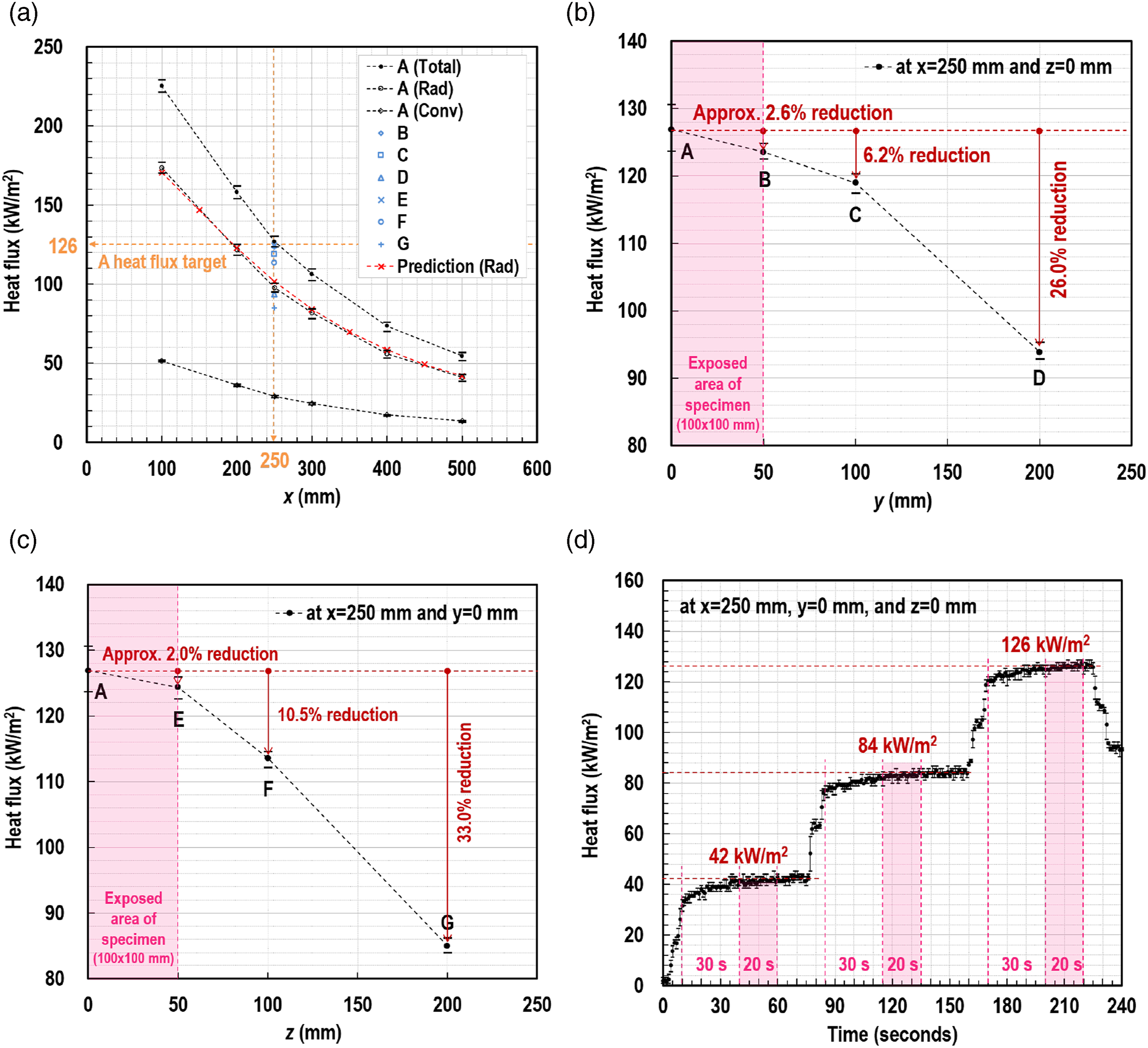
Uncertainty analysis on physical measurements.
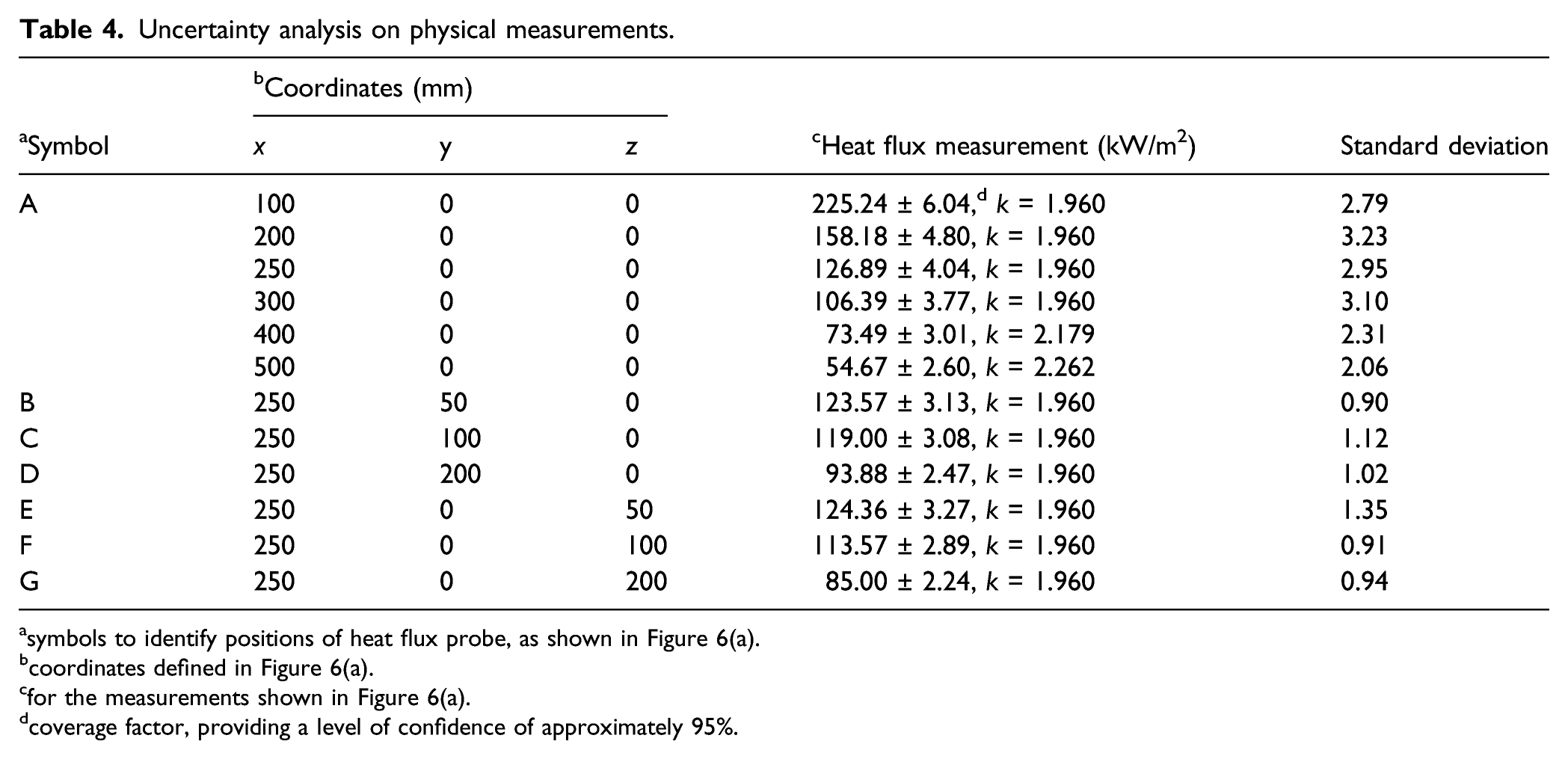
asymbols to identify positions of heat flux probe, as shown in Figure 6(a).
bcoordinates defined in Figure 6(a).
cfor the measurements shown in Figure 6(a).
dcoverage factor, providing a level of confidence of approximately 95%.
For verification purposes, tests were triplicated using the present instrument, according to the two testing conditions proposed in the previous studies
29,38,39
: (1) 1-mm-air-gap between three layers of a specimen, vertically orientated and exposed at 2.5 kW/m2 for 300 s; and (2) no air gap between three layers of a specimen, vertically orientated and exposed at 2.5 kW/m2 for 600 s. The selection of the low-intensity-exposure data was intended not to allow the temperature-time-profile results to be affected by any thermal decomposition (or combustion) of fabric samples, as the specimens tested in this work may have different thermal properties with those used in the previous studies. All the temperature-time histories were measured at the back surface of the thermal liner, and the air gap between the thermal liner and sensing part was maintained as 6.5 mm. Figures 13(a) and (b) show the comparisons between the existing and present data obtained under the two different conditions, respectively. Overall, the measurements in the tests were in agreement with those in the prior works. Although disagreements were observed in the cooling-stage, in the temperature-growth and -quasi-steady stages, small discrepancies less than 5°C were maintained.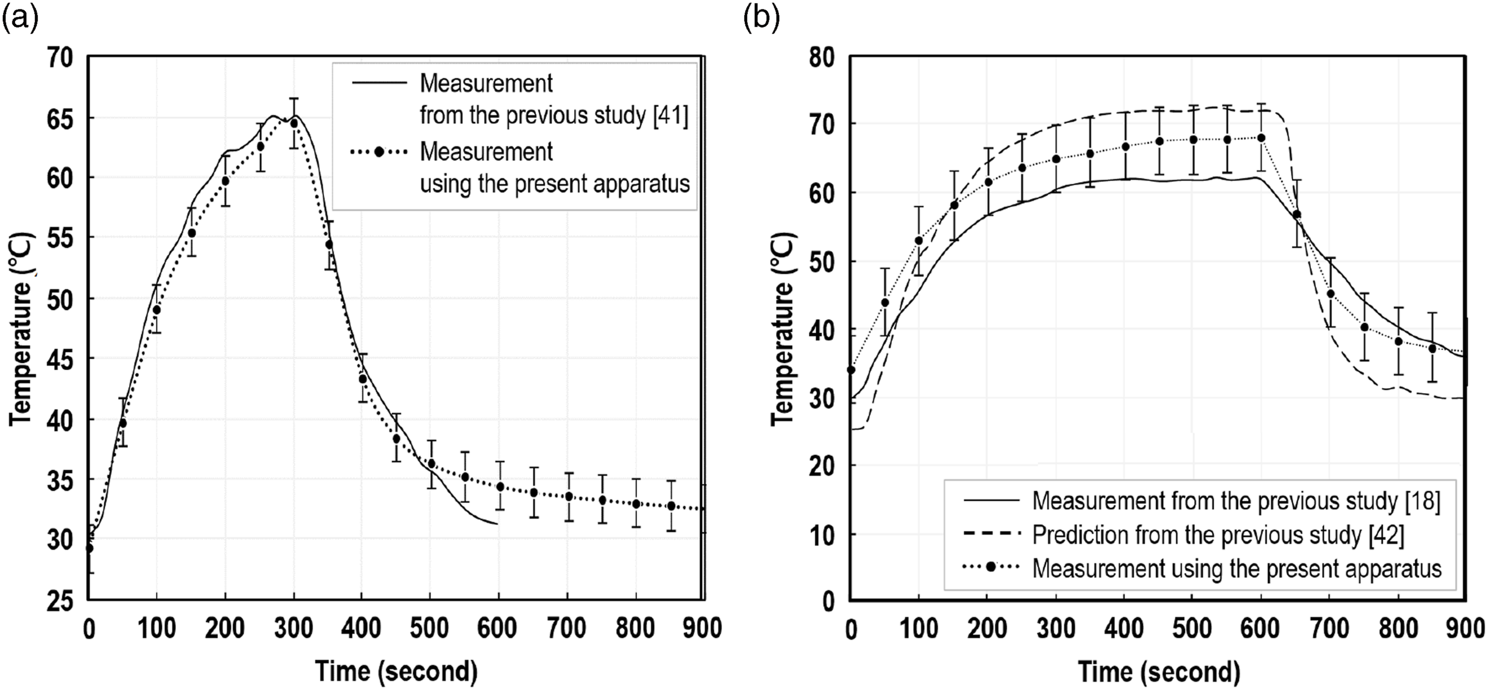
Temperature distribution on vertical orientation surface of specimen
The heater and specimen assembly were vertically oriented to simulate the condition of upstanding firefighters’ garments because the orientation of air gaps between fabrics has an effect on the amount of heat (or temperature) reaching the sensor behind the textiles due to convective motions driven within the gaps.
16,40
To clarify this effect, the fabric samples were tested at the irradiance of 42 kW/m2 for 200 s; the test condition of the 42-kW/m2-intensity and 200-second-period was decided for a comparison with the existing data from the previous works
16,40
performed using the same conditions. Temperature distributions on the rear surface of the thermal liner were measured using the four thermocouple assemblies. The thermal layer’s front surface was observed with unaided eyes, as shown in Figure 14(c). The images of the other layers after tests are shown in Figures 14(a) and (b). The front surfaces of the specimen exposed to 42 kW/m2 for 200 s: (a) outer shell, (b) moisture barrier and (c) thermal liner.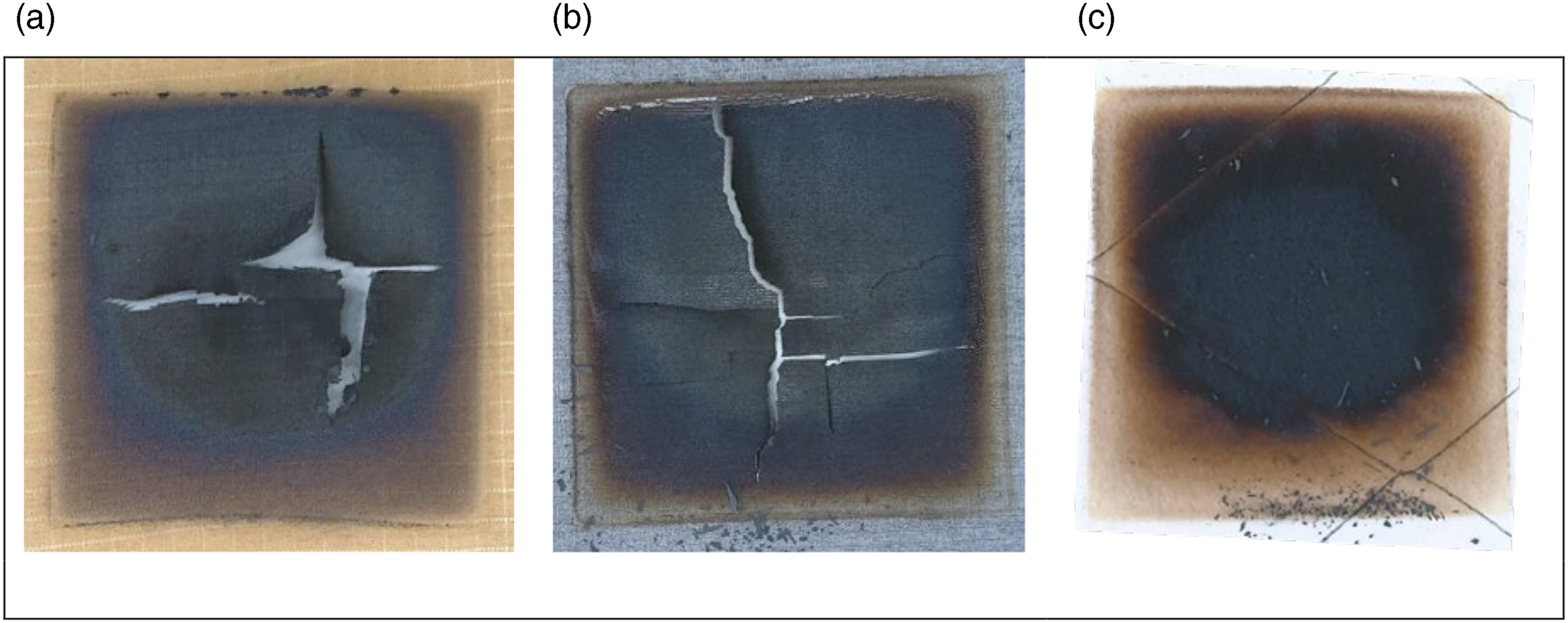
Figures 15(a) and (b) respectively, illustrate contour-line maps of surface temperatures of horizontal and vertical orientation specimens based on the measurement and observation; the diagram regarding the horizontal orientation originated from the previous studies.
16,40
The horizontal orientation formed into temperature contour lines with regular rectangular patterns, whilst the vertical configuration resulted in those with different patterns. This indicates that proper measuring points should be selected when obtaining a representative (or average) value of the surface temperature of specimens from the vertical configuration apparatus.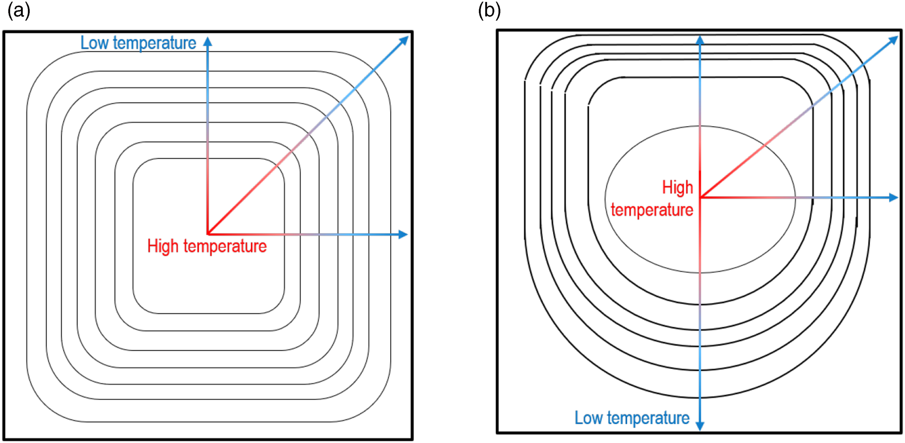
Conclusions
In this paper, the development process of a bench-scale apparatus was discussed that is used to quantitatively evaluate the thermal protective performance of fabric samples. The new instrument was optimised to create a critical thermal environment beyond the standard level representing the conventional flash fires (i.e. 126 kW/m2). The critical condition was proposed because the amount of heat released from modern fires often exceeds the standard level, which could endanger the fire-hazard responders wearing the garments assessed under the typical thermal environment.
It was primarily focused on developing a heating part and a specimen assembly with a sensing system. As the quantity was associated with several aspects such as the type of heat-source, number of heating elements, position of the specimen assembly, heater-capability and apparatus-sustainability, a preliminary test was conducted to determine the aspects using a pilot instrumental model. The developed heating condition was secondarily validated examining the heat flux variation along the horizontal distance between the heater and specimen, the heat flux uniformity throughout and heat flux consistency on the exposed surface of the specimen. At a 250-mm-distance position from the heater, the 100 × 100-mm-size fabric surface was exposed to 126 kW/m2 with a small heat flux reduction less than 3% of the central heat flux and a consistent emission for longer than 30 s. As a result of the optimisation, 36 infrared halogen tubular quartz lamps were arranged in two layers; the specimen assembly was distanced 250 mm from the heater; and the heater capacity was determined as 76% of the total allowable electric power.
The high-performance heater, specimen assembly and thermal shields can be regularly operated according to a sequential process by a LabVIEW-based in-house program. This software also includes functions of analysing heat transfer through human-tissue layers and evaluating the degree of skin burns. This testing system can contribute to mainly the thermal performance enhancement of emergency responders’ garments and secondarily the testing of any 100 × 100-mm specimens that are supposed to be uniformly exposed at a constant radiant heat over a wide range in a consistent manner.
Footnotes
Declaration of conflicting interests
The author(s) declared no potential conflicts of interest with respect to the research, authorship, and/or publication of this article.
Funding
The author(s) disclosed receipt of the following financial support for the research, authorship, and/or publication of this article: This project is funded by NFA(National Fire Agency) and KEIT(Korea Evaluation Institute of Industrial Technology) through R&D programmes on Development of Fire Safety Technologies for ESS and Hydrogen Facilities (No.20011579) and for Emergency Response to Fire Hazards (No.20008021).
Appendix