
Abstract
The integrated INS/magnetometer measurement is widely used in low-cost navigation systems. The integration has proven more effective in suppressing the divergence of heading than relying solely on a magnetometer because this is susceptible to local magnetic field interference, reducing heading accuracy. Magnetometers sense the local magnetic field that may be interfered by the nearby ferromagnetic material or strong electric currents. Hence, the magnetometer must be calibrated in the vehicle before use. When a magnetometer is installed near power components (engines, etc.), soft iron interference can be ignored. In the vehicle’s external environment, the time-varying hard iron interference can reach 100 times the strength of the geomagnetic field, meaning that a magnetometer cannot function efficiently because its accuracy is so reduced. Hence, the constant hard magnetic interference inside the vehicle is mainly concerned in this paper. An INS/Magnetometer heading estimation algorithm based on a two-stage Kalman filter is proposed to solve the problem by combining inertial sensor and magnetometer with attitude information. In the first stage filter, the constant hard iron interference is estimated by setting upward standing the three IMU axes. In the second stage filter, the INS/Magnetometer heading estimation is implemented. Finally, the results show that the algorithm improves the accuracy of vehicle heading calculations.
Introduction
Vehicle navigation systems can provide real-time and accurate navigation information. The global positioning system (GPS) is currently the most widely used navigation system in such applications. However, the accuracy of GPS could be severely affected or completely interrupted due to several factors such as ionosphere, troposphere, multipath, and signal interference. 1 During GPS outages, INS systems based on Inertial Measurement Unit (IMU), can be used to maintaining a continuous vehicle navigation solution as an alternative.2,3 INS systems obtain the vehicle attitude information via inertial sensors, then they calculate the velocity and position information in the navigation coordinate system based on the given attitude. During its motion, the vehicle is mostly moving in a 2D plane. Therefore, vehicle heading is a key navigation parameter in INS that directly affects vehicle navigation accuracy. Due to the unpredictable noise characteristics of the low-cost IMU, the heading error of the inertial solution continues to accumulate over time.4,5 INS can be integrated with magnetometer information to effectively suppress the divergence error of vehicle heading to improve the accuracy of vehicle navigation systems.5–7
Unfortunately, the magnetometer is susceptible to interference from surrounding local magnetic fields. 8 The distortion of the magnetic field strength prevents the magnetometer from measuring the geomagnetic vector, which, in turn, affects the accuracy of vehicle heading. Magnetic interference caused by magnetic field sources other than the geomagnetic field depends on the platform materials, connectors, and magnetic materials passing near the magnetometers. 9 Magnetic interference can be divided into hard iron interference and soft iron interference. Hard iron interference is created by objects that produce a magnetic field. Soft iron interference is considered deflections or alterations in the existing magnetic field. In most cases, hard iron distortions will have a much larger contribution to the total uncorrected error than soft iron. Especially when considering the influence of ambient current on magnetometer measurements, hard iron interference tends to surpass environmental interference. 10 Note that this situation is typical when the magnetometer is used indoor or in the contexts where it is mounted near to motors or other powered elements. Depending on their powering current, the above-mentioned elements create variable perturbing magnetic fields which highly affect the sensor hard iron, whereas they have a low effect on the soft iron, justifying for considering in some cases only hard iron perturbation while neglecting soft iron ones. Therefore, when a magnetometer is installed near power components (engines, etc.), it can be assumed that it is not subject to soft iron interference, and only hard iron interference is considered. 9
Magnetometers are particularly sensitive to hard iron interference outside vehicles, such as unpredictable huge currents in nearby cables and heavy metal pipes laid nearby. Such time-varying hard iron interference reaches as much as 100 times the strength of the geomagnetic vector. Hence, magnetometers cannot be used when in close proximity to these devices. 11 In such an instance, which is outside of the scope of this paper, it is not necessary to calibrate magnetic interference. The hard iron interference sources that magnetometers measure in a vehicle include the magnet platform, the internal magnets of the vehicle, and the stable current of the power components. These hard iron interference components can be considered constants during vehicle operation. In this paper, a constant hard iron interference compensation method is proposed to improve the vehicle heading accuracy of an integrated INS/Magnetometer system.
There are two traditional solutions to magnetic interference calibration for magnetometers. 9 The first requires accurate external information sources (e.g. turntable, etc.), but this is costly. 12 To reduce costs, many researchers focus on automatic calibration techniques, such as ellipsoid fitting.8,13,14 The Earth’s magnetic vector is constant, and when a magnetometer rotates around a specific point, its measurement should be normally distributed on a sphere. However, magnetic interferences in the measurements cause the data distribution to take an ellipsoidal shape. Therefore, the calibration of magnetic interference can be solved by fitting this ellipsoid into a sphere. 9 The calibration parameters can be solved by maximum likelihood estimation15,16; accordingly, an iterative algorithm, based on least square, is proposed for magnetometer calibration. 17 This magnetic interference calibration requires the measurement to be taken while rotating around three axes in space. The more data points that cover the entire space, the greater the calibration accuracy. Therefore, these methods are complicated with long calibration time, and the optimal estimate cannot be obtained when there is noisy interference. The particle swarm optimization algorithm is an alternative that could be used for magnetometer calibration. The method can be used to build a more accurate nonlinear model without the need for initial parameters estimation. Although it improves the calibration accuracy, the algorithm increases the computational burden.18,19 Many researchers focused on magnetometer calibration methods based on magnetometer/inertial sensor fusion. 20 However, since low-cost inertial sensors have complex error characteristics, achieving simultaneous calibration of the magnetometer and inertial sensors is a key to improving the magnetic heading information.
In this paper, an INS/Magnetometer heading estimation algorithm based on atwo-stage Kalman filter is proposed to solve the problem by combining inertial sensor and magnetometer with attitude information. In the first stage filter, the constant hard iron interference is estimated by setting upward standing the three IMU axis. In the second stage filter, the INS/Magnetometer heading estimation is implemented. Moreover, the correctness and effectiveness of the proposed algorithm are verified by actual driving experiments. The structure of the rest of this paper is as follows: Section 2 proposes a constant hard iron interference estimation method based on IMU three axes upward standing. Section 3 proposes a vehicle heading estimation technique based on INS/magnetometer information integration. Section 4 outlines the details of the experiment setup and analysis of results. Section 5 summarizes the paper and suggests directions for future research.
Constant hard iron interference estimation
This section is aimed at modeling the constant hard iron interference of the magnetometer in the vehicle when magnetometer measurements are available. First, a linear model of attitude error and INS/magnetometer constant error is established according to the characteristics of the vehicle’s motion plane. Second, constant hard iron interference calibration is performed using a Kalman filter by temporarily holding static and upward the three axes of the magnetometer.
State model
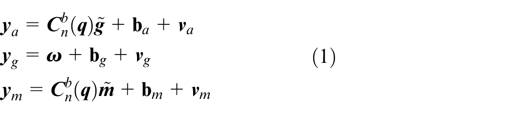
While stationary the accelerometer can measure gravity acceleration under ideal conditions. Since the low-cost gyroscope cannot accurately sense the earth’s rotation angular velocity, the true value of the vehicle’s angular velocity can be assumed to be zero. Although the magnetometer can measure geomagnetism under ideal conditions, noise, device errors, and environmental interference are typically present. Accordingly, the outputs of the accelerometer, gyroscope, and magnetometer under static conditions are given in equation (1)
where,

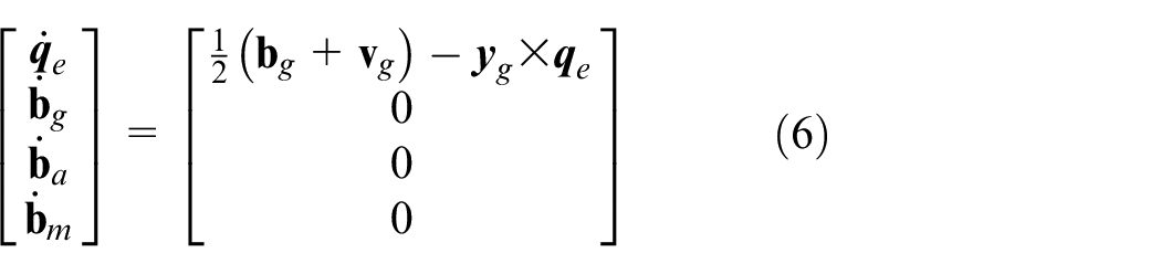
In the static state, the quaternion error


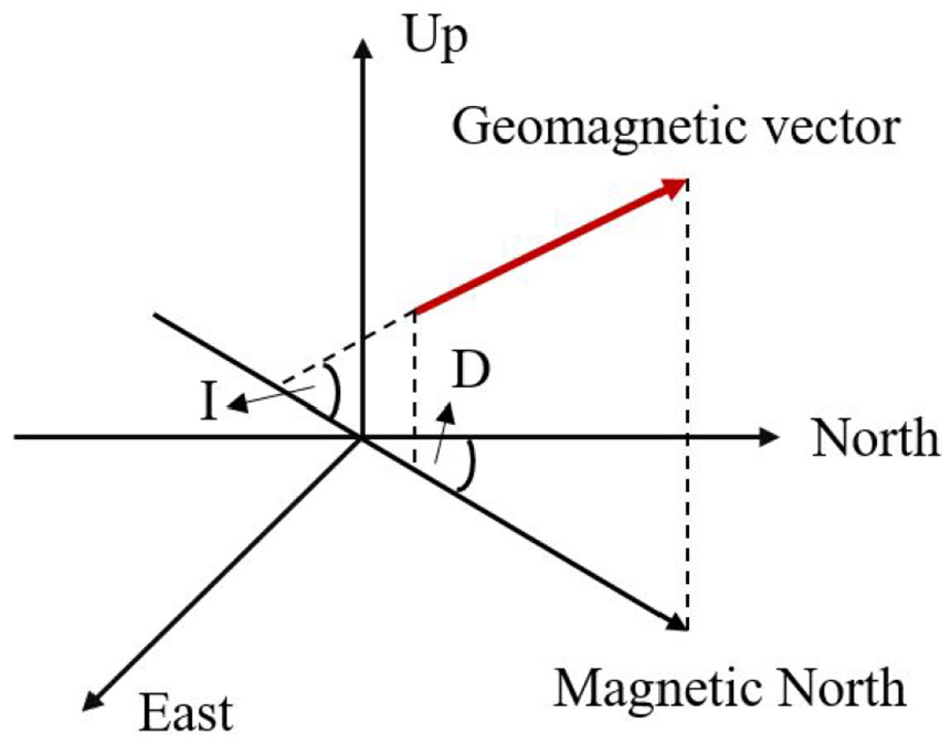
Geomagnetic vector projection under local horizontal plane.
where inclination

According to equations (1), (2), and (3), one can have:
Observation model
System observations consist of the difference between the measured accelerations

When using the gyroscope output to calculate the attitude rotation matrix, with the assumption that
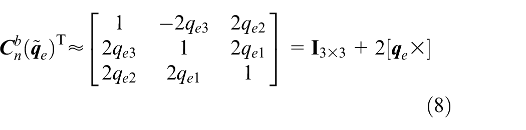
Substituting equation (8) and equation (1) yields the observation model:
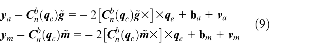
According to equation (9), an accurate geomagnetic vector can correct heading by limiting quaternion error. However, because the magnetometer has constant hard iron interference, the error term
where
In most road conditions where a vehicle is traveling in a horizontal plane, the pitch and roll angles can only have small and slow changes, which can be ignored. Therefore, many researches have simplified the 3D system model to the 2D model. This article similarly assumes flat road conditions and hence, the pitch and roll angles are set to zeros (
According to equation (11), the parameters related to the magnetometer in equation (9) can be rewritten as follows:
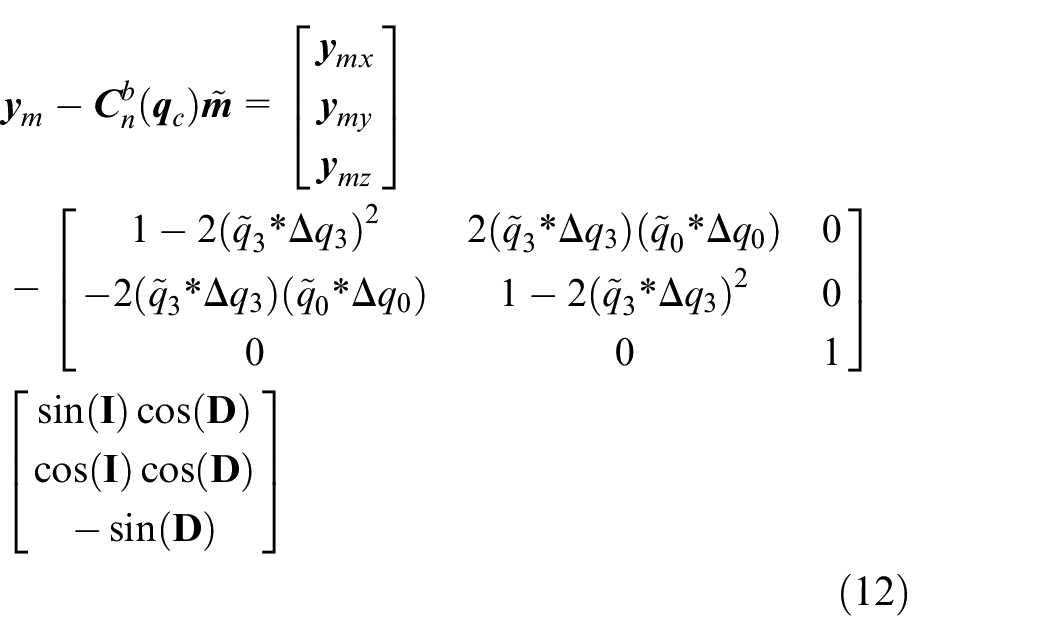
From equation (12), it can be seen that the attitude error caused by constant hard iron interference will not affect the accuracy of the constant hard iron interference estimation accuracy of the upward axis of the IMU. Hence, calibration is performed using a Kalman filter and by holding the magnetometer’s three axes facing upwards static for a short period, which is shown in Figure 2.
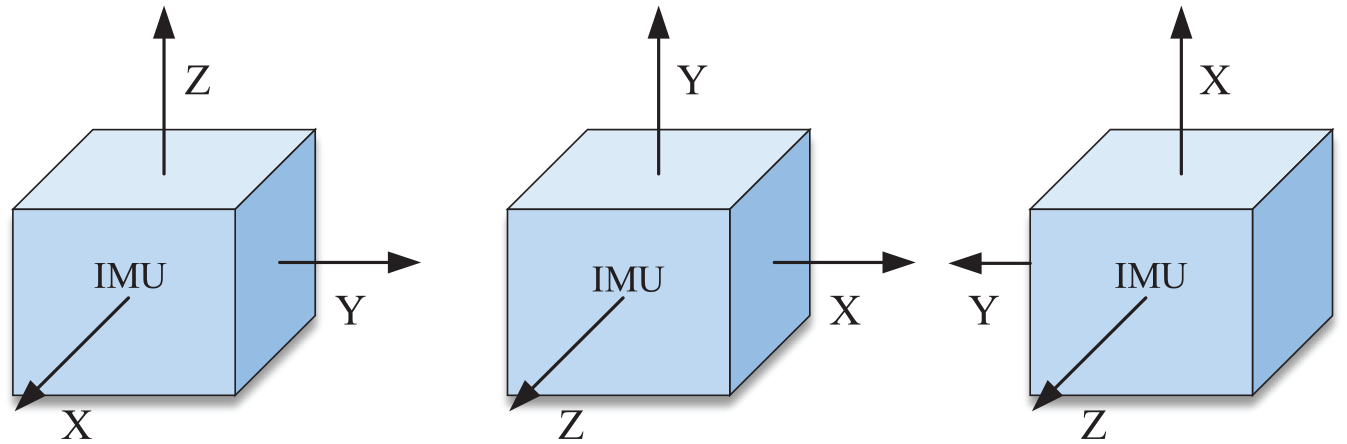
Set upward standing the three IMU axes.
Vehicle heading estimation based on INS/Magnetometer
After the constant hard iron interference is estimated in section 2, the magnetometer can assist the INS to obtain an accurate vehicle heading. In this section, the INS/Magnetometer heading estimation will be implemented. Because the acceleration reference in n-frame cannot be obtained when the vehicle is in motion. Different observation models are adopted in this section according to different movement states of the vehicle. Figure 3 shows a block diagram of the proposed INS/Magnetometer heading estimation algorithm. The calibrated magnetometer, accelerometer, and gyroscope data are the input of the heading estimation algorithm, the acceleration, and angular velocity are used to calculate inertial navigation system. The observation information is provided by the magnetometer and accelerometer when a vehicle is static. When moving, the observation information is only provided by the magnetometer. Kalman filter is adopted for information fusion.
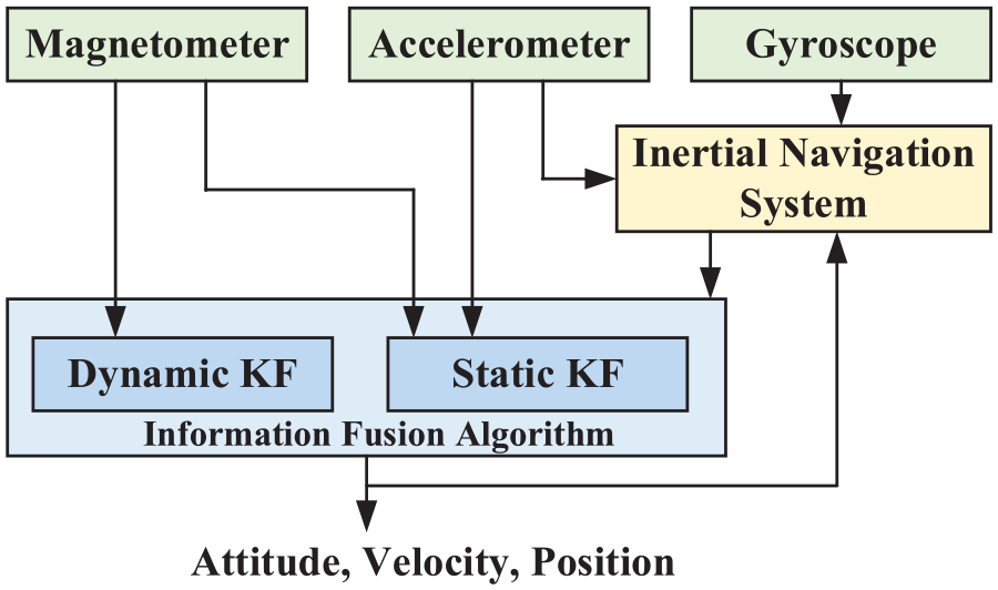
Block diagram of INS/Magnetometer heading estimation algorithm.
State model
After applying a Kalman filter using the models introduced in Section 2, the constant error can be estimated including accelerometer bias, gyroscope drift, and magnetometer constant hard iron interference. There are still residuals in these estimations that cause varying degrees of errors in the navigation system. These residuals can be defined as:
Cumulative errors in the INS: residuals of accelerometer bias and gyroscope drift.
Constant errors in filter update: measurement residuals of accelerometer bias and magnetometer constant hard iron interference.
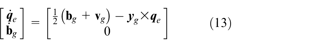
The magnitude of these residuals is quite small, so residuals that produce constant errors in filter updates can be ignored. In the INS, owing to utilization of integral operations, small errors may rapidly grow and continue to diverge after long-term accumulations. Since the accelerometer residual has no effect on heading estimation, the gyroscope residual is the focus of this section. In summary, the system state model is formulated as follows:
Observation model
For static status, the observation model becomes:
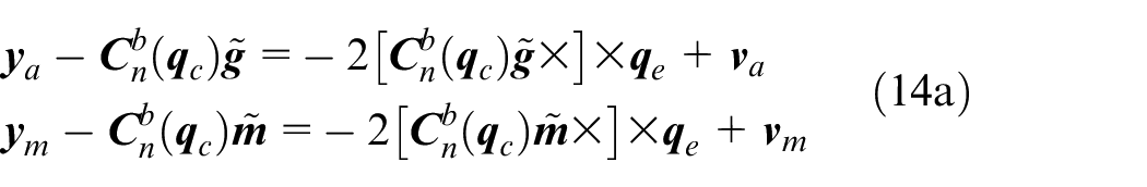
For dynamic status, the observation model becomes:

According to the state model and observation model in equation (13) and (14), a Kalman filter can be adopted to estimate
Vehicle heading calculation
The
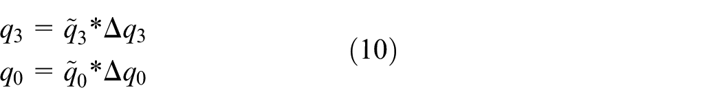
In the iterative process of the filter, the quaternion of attitude is compensated by using the estimated

where
where

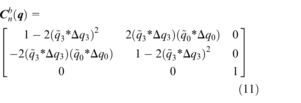
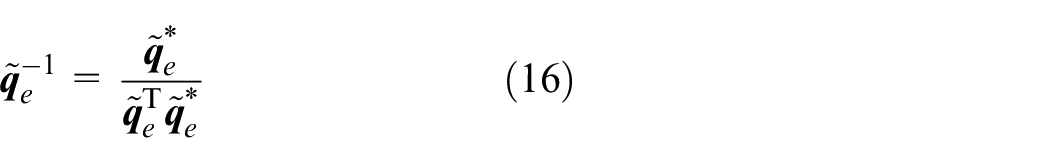
Then, we normalize the quaternion error after compensation
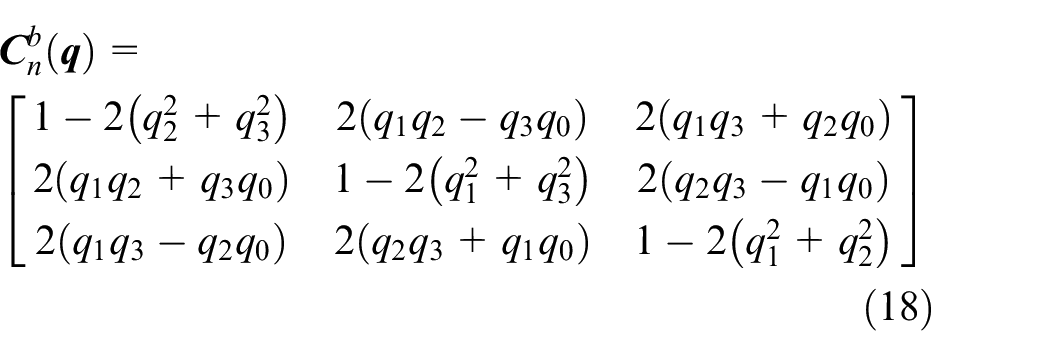
As a result, the updated rotation matrix becomes:
The trigonometric function of
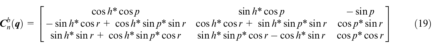
where

Finally, the INS/Magnetometer heading is obtained.
Experiments and result analysis
To verify the performance of the proposed algorithm, an MTi-G710, by Xsens, is used to conduct actual experiments. The MTi-G710 is composed of various sensors, such as accelerometers, gyroscopes, magnetometers, a barometer, a thermometer, and a GPS -Beidou receiver, etc., and it provides raw sensor data and navigation information based on multi-sensor fusion. The experiment settings are shown in Table 1.
Experiment settings.
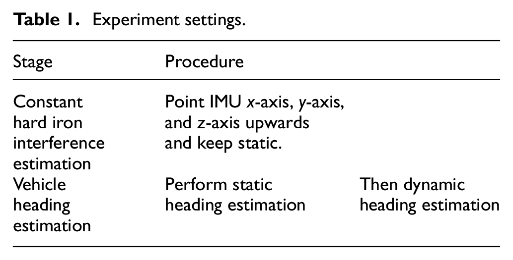
The results of experiments are represented by vehicle heading. Hence, accurate reference heading information is required for evaluation purposes. In the static heading experiments, GPS/INS systems cannot provide static heading information; consequently, there is no heading reference for static experiments. However, the accuracy can be evaluated by the heading difference between two IMUs placed in parallel, which is shown in Figure 4. Two IMUs are mounted in parallel and placed horizontally in the vehicle (The IMUs are fixed in a box full of heavy objects and firmly sealed to ensure that it is tightly fixed to the vehicle body while driving), IMUs are connected to a laptop via USB to observe and collect data from magnetometers, gyroscopes, and accelerometers in the vehicle. Static experiments’ results are considered accurate when the heading results of two IMUs are consistent after hard iron interference calibration. In dynamic experiments, the multi-sensor fusion heading provided by MTi-G710 is used as a reference.
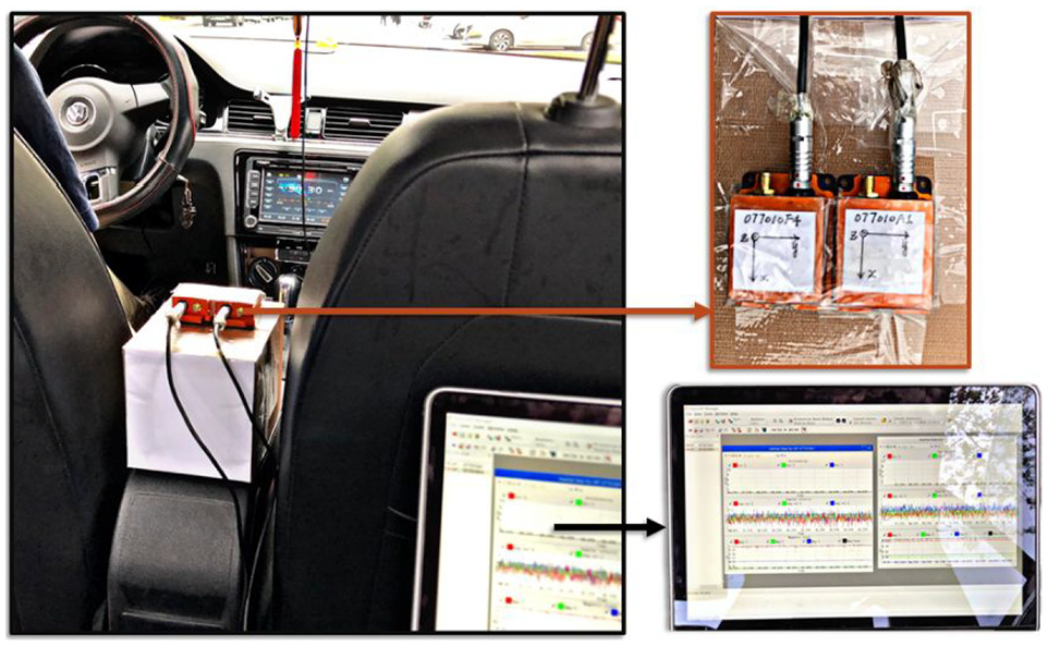
Schematic diagram of experiment platform.
Constant hard iron interference calibration experiments
An open area with a relatively stable magnetic field environment can be selected as the experiment’s location in this stage. We manually operate the platform, let the two IMUs’ three axes successively point upward and keep static for 2 min each time. The setup is connected to a laptop computer to synchronously collect the accelerometer, gyroscope, and magnetometer measurements of two IMUs at a frequency of 100 Hz. The results of constant hard iron interference calibration experiments are shown in Figure 5. Numerical results are also given in Table 2.
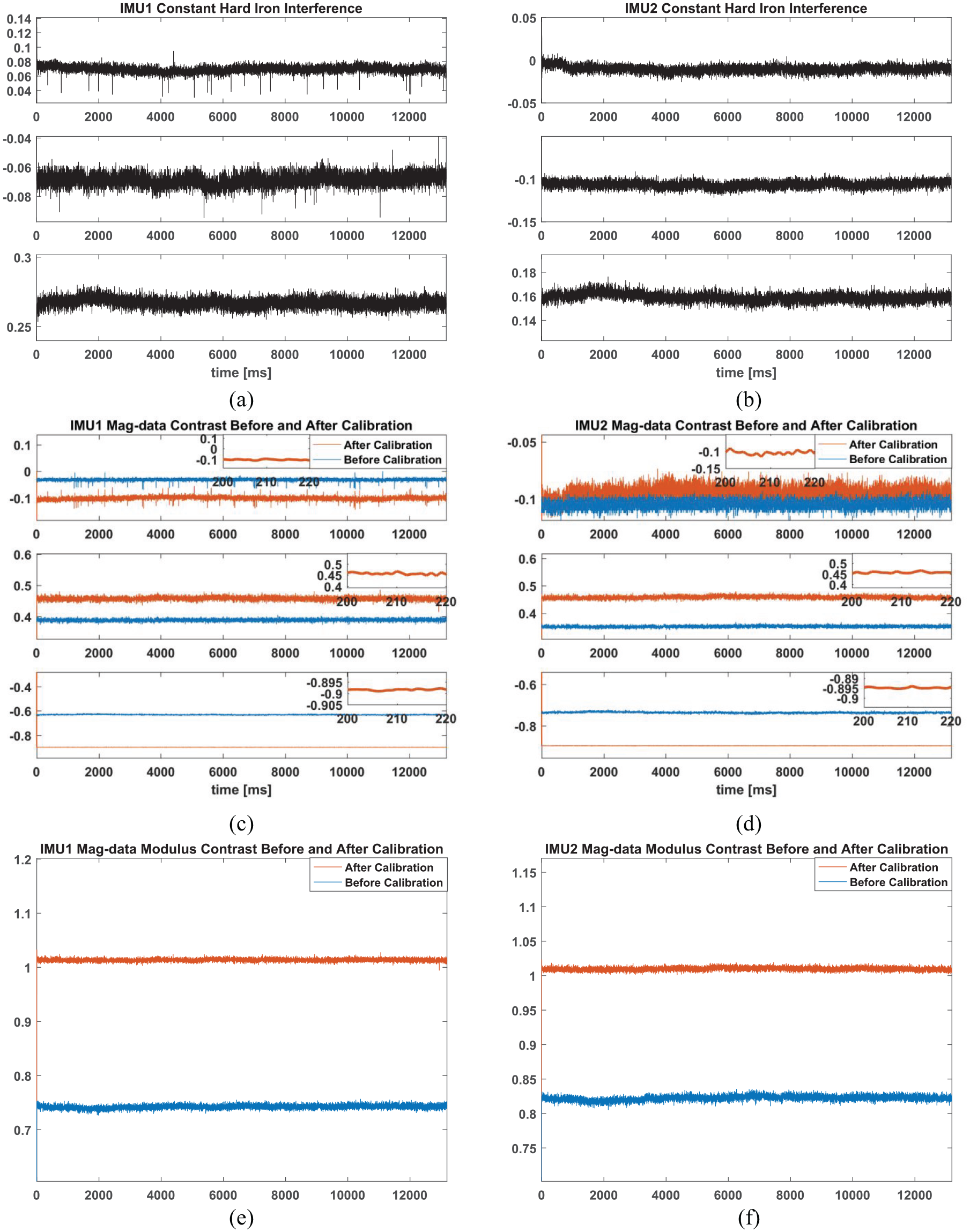
Estimation results of constant hard iron interference: (a) IMU1 constant hard iron interference, (b) IMU2 constant hard iron interference, (c) IMU1 Mag-data contrast, (d) IMU2 Mag-data contrast, (e) IMU1 Mag-data modulus contrast, and (f) IMU2 Mag-data modulus contrast.
Data analysis of hard iron interference estimation.
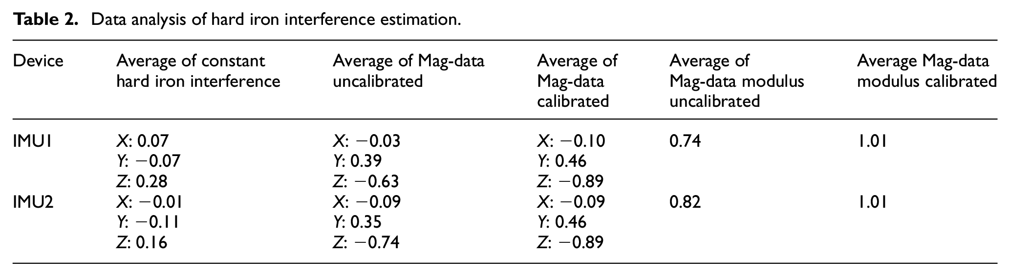
The constant hard iron interference estimation results of two IMUs are illustrated in Figure 5(a) and (b), respectively. The constant hard iron interferences are relatively stable during the test phase. The two magnetometers have different error characteristics. The average constant hard iron interference of IMU1 and IMU2 are
Comparison of magnetic field strength data before and after calibration of IMU1 and IMU2 are illustrated in Figure 5(c) and (d). The blue lines and red lines are magnetometer measurements before and after calibration, respectively. The average of magnetometer measurements for IMU1 and IMU2 before calibration are
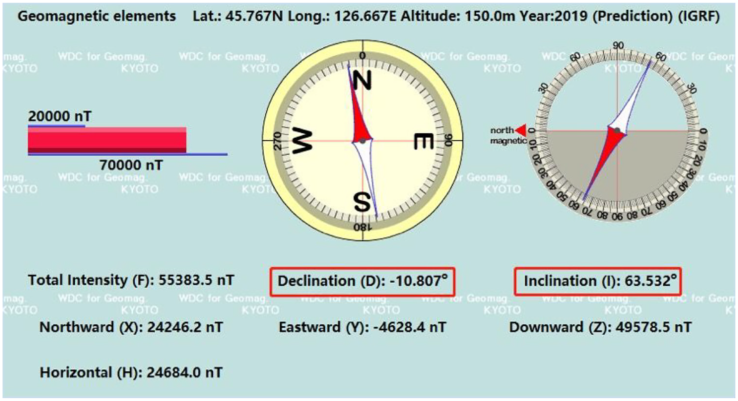
Geomagnetic information of test site (Harbin, China).
Vehicle heading estimation base on INS/magnetometer fusion
Static heading estimation
When IMU1 and IMU2 are placed in tandem, the theoretical values of their headings should be equal. The results in Figure 5 show that the two IMUs have different magnetometer error characteristics. Hence, the two IMUs are placed in tandem and operated synchronously. The estimated results are considered accurate when the estimated heading results of the two IMUs at any two positions are consistent. Figure 7 shows the two IMUs’ heading estimation based on the INS/Magnetometer before and after calibration at two arbitrary positions in a static state. The blue lines and red lines are the estimated heading of the two IMUs before and after calibration.
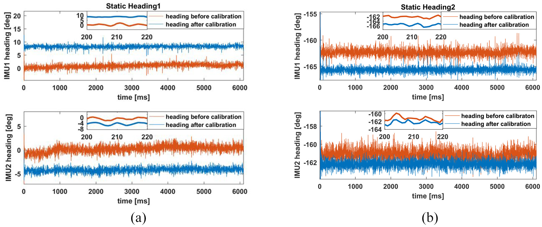
Estimation results of static heading: (a) static heading 1 estimation and (b) static heading 2 estimation.
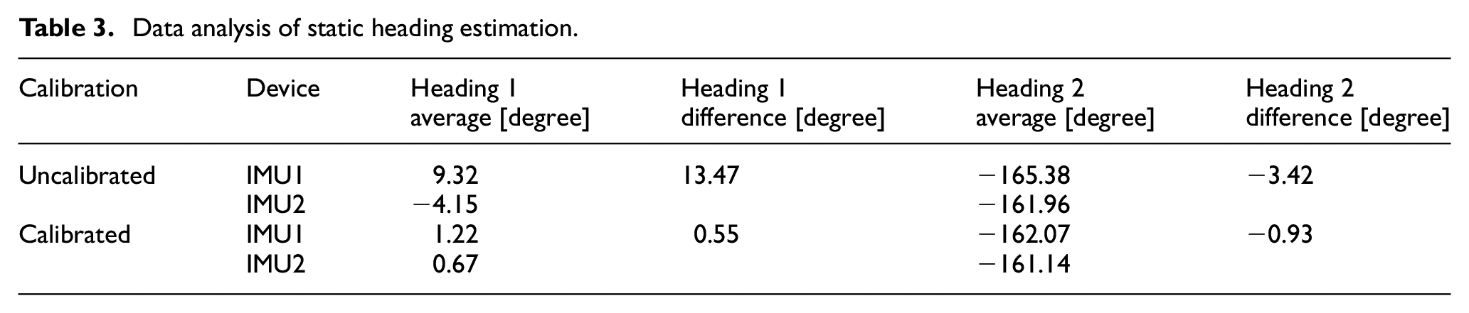
According to Figure 7, the IMUs data are affected by noise in a small range. The data analysis of two IMUs at position 1 and position 2 is illustrated in Table 3. Before the constant hard iron interference calibration, the estimated heading results of IMU1 and IMU2 at position 1 are 9.32° and −4.15°, and they have a heading difference of 13.47°. The estimated heading results of IMU1 and IMU2 at position 2 are −165.38° and 161.96°, and their heading difference is −3.42°. After calibration, the estimated heading results of IMU1 and IMU2 at position 1 are 1.22° and 0.67°, and they have a heading difference of 0.55°. The estimated heading results of IMU1 and IMU2 at position 2 are −162.07° and −161.14° respectively, and the heading difference is 0.93°. The heading differences between the two parallel IMUs at position 1 and position 2 are significantly reduced.
Data analysis of static heading estimation.
Dynamic heading estimation
Dynamic experiments were conducted in Harbin (Heilongjiang, China). The traveled path is shown in Figure 8. The platform with two parallel IMUs is horizontally fixed in the vehicle. During the trajectory, a laptop computer is used to simultaneously collect the measurements of the accelerometer, gyroscope, and magnetometer at a frequency of 100 Hz. The dynamic estimated headings of two IMUs before and after magnetic interference calibration are shown in Figure 9. The heading reference is provided by the MTi-G710 units.
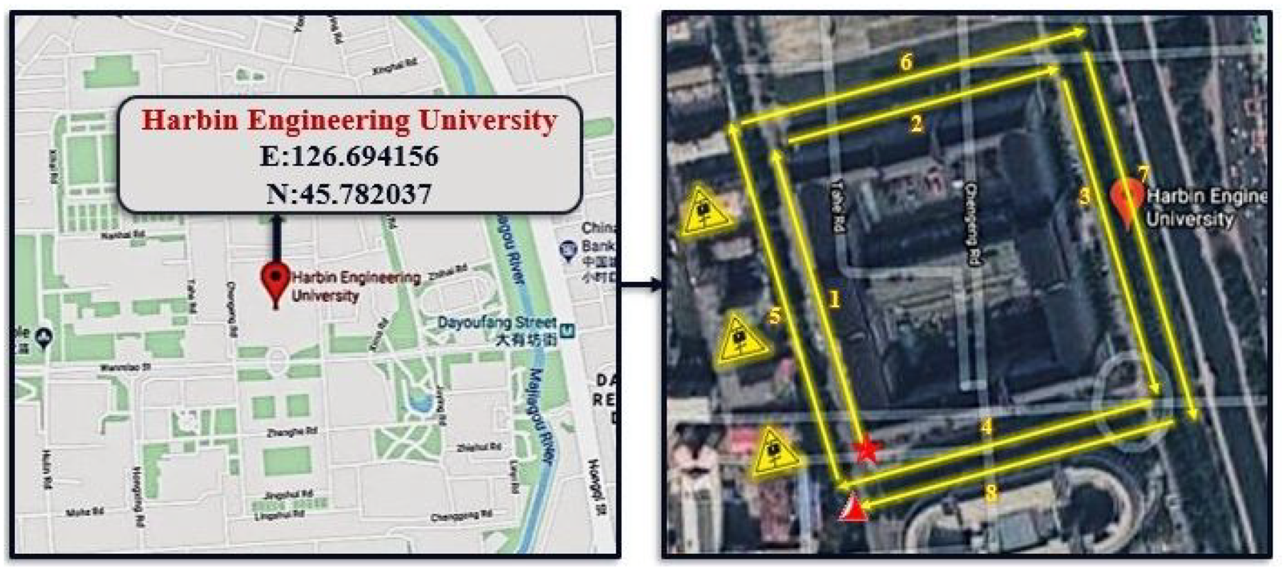
The specific path of the dynamic experiments.
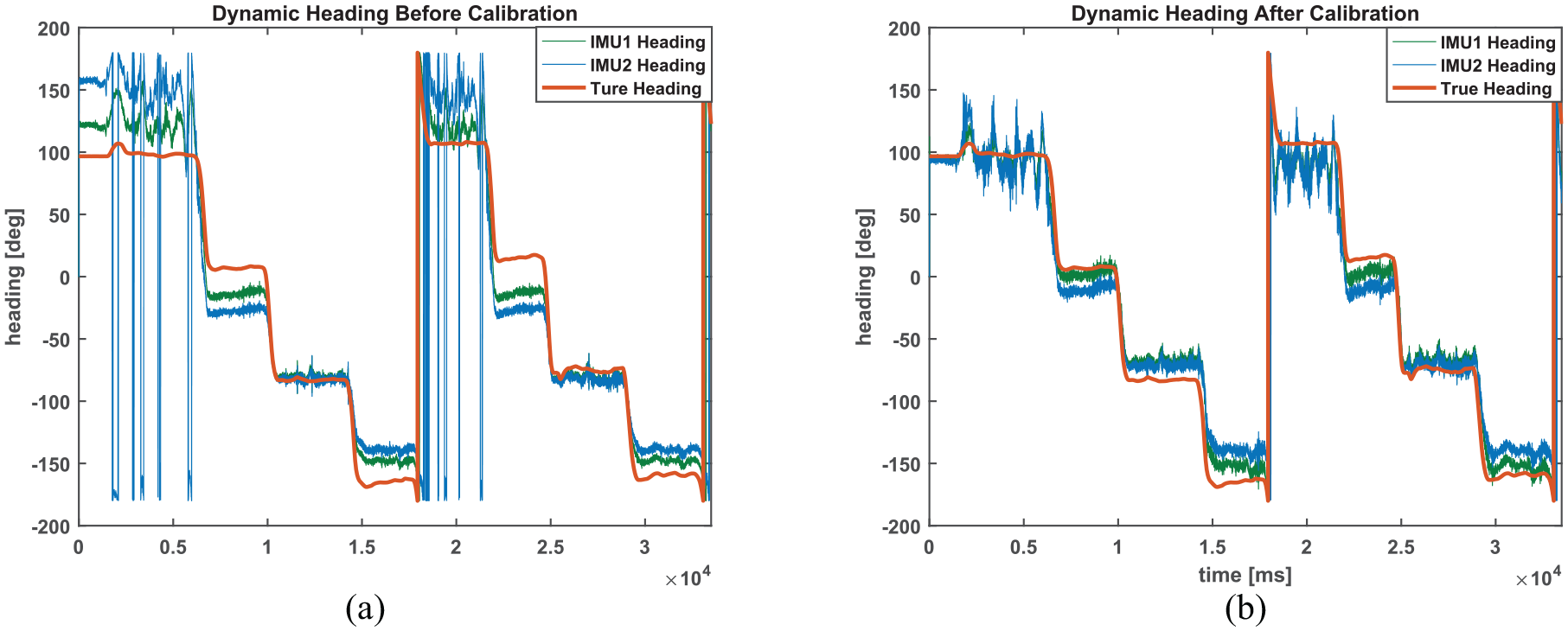
Estimation results of dynamic heading: (a) dynamic heading before calibration and (b) dynamic heading after calibration.
In Figure 8, the red asterisk marks the starting point, and the red triangle indicates the endpoint. The yellow triangles indicate high-voltage lines with large time-varying magnetic interference. The trajectory path can be divided into eight straight lines. Due to the proximity to the high-voltage lines, the heading of line 1 and line 5 obtained by INS/Magnetometer fusion will be greatly disturbed.
Figure 9 shows the dynamic estimated heading comparison of the two IMUs before and after calibration. The red line is the reference from the MTi-G710 based on multi-sensor integration. Comparing Figure 9(a) and (b), the accuracy of the vehicle heading based on INS/Magnetometer integration is significantly improved after constant hard iron interference calibration. Due to the proximity to high-voltage power lines, the estimated heading of line 1 and line 5 in the trajectory is significantly affected by time-varying random interference, thus still has a wide range of fluctuations after constant hard iron interference calibration.
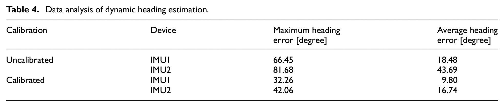
The data analysis of the dynamic heading estimation is illustrated in Table 4. Before constant hard iron interference calibration, the maximum heading errors of IMU1 and IMU2 are 66.45° and 81.68°, with average heading errors of 18.48° and 43.69°. After calibration, the maximum heading errors of IMU1 and IMU2 are 32.26° and 42.06°, respectively, and the maximum heading errors were reduced by 51.45% and 48.51%. The average heading errors of IMU1 and IMU2 are 9.80° and 16.74°, meaning that these were reduced by 46.97% and 61.68%.
Data analysis of dynamic heading estimation.
Conclusion
This paper introduces an INS/Magnetometer heading estimation algorithm based on a two-stage Kalman filter by combining inertial sensor and magnetometer with attitude information. In the first stage filter, the constant hard iron interference is estimated by setting upward standing the three IMU axes. In the second stage filter, the INS/Magnetometer heading estimation is implemented. The correctness and effectiveness of the proposed algorithm are verified using real trajectory experiments. The algorithm can effectively solve the problem of constant hard iron interference on INS/Magnetometer fusion in the vehicles, and hence, improve the accuracy of the INS/Magnetometer-estimated heading. The results show that the INS/Magnetometer vehicle heading estimation algorithm based on constant hard iron interference calibration has obtained a more accurate estimation of the vehicle. As an extension of this work, the influence of magnetometer noise, soft iron interference, and time-varying hard iron interference on the accuracy of heading estimation will be considered.
Footnotes
Declaration of conflicting interests
The author(s) declared no potential conflicts of interest with respect to the research, authorship, and/or publication of this article.
Funding
The author(s) disclosed receipt of the following financial support for the research, authorship, and/or publication of this article: The paper is supported by National Natural Science Foundation of China (No.51879046), Natural Science Foundation of Heilongjiang Province of China (No.YQ2019F001), and China Scholarship Council.