
Abstract
The paper proposes an angular velocity fusion method of the microelectromechanical system inertial measurement unit array based on the extended Kalman filter with correlated system noises. In the proposed method, an adaptive model of the angular velocity is built according to the motion characteristics of the vehicles and it is regarded as the state equation to estimate the angular velocity. The signal model of gyroscopes and accelerometers in the microelectromechanical system inertial measurement unit array is used as the measurement equation to fuse and estimate the angular velocity. Due to the correlation of the state and measurement noises in the presented fusion model, the traditional extended Kalman filter equations are optimized, so as to accurately and reliably estimate the angular velocity. By simulating angular rates in different motion modes, such as constant and change-in-time angular rates, it is verified that the proposed method can reliably estimate angular rates, even when the angular rate has been out of the microelectromechanical system gyroscope measurement range. And results show that, compared with the traditional angular rate fusion method of microelectromechanical system inertial measurement unit array, it can estimate angular rates more accurately. Moreover, in the kinematic vehicle experiments, the performance advantage of the proposed method is also verified and the angular rate estimation accuracy can be increased by about 1.5 times compared to the traditional method.
Introduction
The angular velocity of the vehicles, such as the multi-rotor unmanned aerial vehicle (UAV), the car or other vehicles,1–5 is usually measured by microelectromechanical system (MEMS) gyroscopes equipped in the navigation system. Thus, the angular velocity can be measured more accurately by improving the measurement accuracy of MEMS gyroscopes. With respect to the improvement of the measurement accuracy, a MEMS gyroscope array is designed by capitalizing on the decreasing price, size, and power consumption. In such a design, multiple gyroscope measurements are fused through different filter frameworks and signal models,6–9 and a non-negligible reduction in the measurement errors can be obtained from the redundant measurements, see, for example, the Allan variance analysis. 10 However, limited by the production process, the measurement accuracy of MEMS gyroscopes cannot be improved and the measurement range cannot be widened simultaneously, even in the array. Since the angular velocity of all points on a rigid object is the same, no additional information, except that from redundant measurements, is obtained from gyroscopes spatially distributed in the array. Nevertheless, if multiple MEMS accelerometers are integrated in an array, the angular rate measurements will be widened effectively. This is because the angular velocity with arbitrary magnitudes and angular acceleration can be obtained from the spatially distributed accelerometer measurements.11–13 Although the accelerometer array can widen the measurement range of the angular velocity, it cannot accurately estimate the angular velocity for the centrifugal force quadratically depends on the angular speed. With respect to such a problem, a variety of approaches are presented in previous works,14–18 but these methods inevitably increase the size of such a system and increase the complexity of the hardware design.19–22 Referring to design ideas of the above sensor array,23,24 a MEMS inertial measurement unit (IMU) array cannot only improve the measurement accuracy but also widening the range of the angular velocity, because MEMS IMU is consisted of the MEMS gyroscope and accelerometer. MEMS IMU can be shorted as MIMU in the paper. In the paper, we apply the MIMU array to the vehicles and carry out some theoretical researches and simulation analysis.
One of the questions when using the MIMU array is how to fuse the redundant output of gyroscopes and accelerometers. Regarding inertial arrays that consist of multiple IMUs, the measurement fusion problem has mainly been studied in the framework of global navigation satellite system aided inertial navigation systems.25–29 In the literatures, the proposed information fusion approaches can be broadly grouped into two categories. In the first category, the IMU measurements are fused before they are used in the inertial navigation systems; a weighted average is used and the spatial separation of the sensors is neglected commonly. In the second category, they are fused after being processed by several parallel inertial navigation systems. And a few discussions on the pros and cons of the two approaches, as well as an evaluation of different measurement fusion methods, have been presented in Bancroft and Lachapelle. 26 Based on the MIMU array design, Skog et al. 24 posed the problem of fusing the measurements from an array of accelerometer and gyroscope triads as a parameter estimation problem for the first time. The method derives a maximum likelihood based measurement fusion, outperforming the current state-of-the-art method for measurement fusion as shown in simulation results. Moreover, it allows for smaller and cheaper senor arrays to be constructed. In the paper, such a fusion method is called maximum likelihood estimation (MLE). MLE used in the MIMU array has been demonstrated that it is beneficial to improve performance in terms of pedestrian tracking, but it only gives suboptimal performance. Thus, how to fuse the multiple measurements of the MIMU array for getting more optimal performance is still not clear. Furthermore, there has not been the research applying the MIMU array to the vehicles yet, such as the multi-motor UAV, and another significant issue is whether the current fused method should also be optimized when used in the vehicles. On the basis of the above analysis and being inspired by the fusion method of the MIMU array in Skog et al., 24 this paper proposes an improved angular velocity fusion method of the MIMU array.
The proposed method models the angular velocity according to kinetic characteristics of the vehicles, which refers to the work by Liu et al. 9 The model is regarded as the state equation. And it regards the signal model of gyroscopes and accelerometers on the array as the measurement equation. Since the accelerometers’ output-based measurement equation is associated with the angular velocity quadratically, the angular velocity is estimated by the extended Kalman filter (EKF). Moreover, the state and measurement noises are correlated in our established models, thus the traditional EKF coping with the state and measurement uncorrelated noises should be also improved so as to estimate the angular rate accurately. To discuss and demonstrate the performance of our improved fusion method, the paper conducts the simulation and kinematic vehicle experiments. The experiment results demonstrate that the innovation of the paper can be summarized into two main points as follows:
The angular velocity can be adaptively estimated according to the angular rates with arbitrary magnitudes, which owes to the signal model of the MIMU array and the state equation with an adaptive model of the angular velocity. Based on the presented fusion model, the angular velocity is estimated more accurately compared with the MLE method;
By optimizing the traditional EKF equations, the angular velocity of MIMU array can be estimated even in the filter equations, where the state and measurement noises are correlative.
The remainder of this paper elaborates the research mentality in detail and is organized as follows. Section “Angular velocity fusion method of the MIMU array” derives the angular velocity fusion method of the MIMU array based on EKF with correlated system noises. Section “Experiments and analysis” discusses and analyzes the simulation experimental results. And then conclusions are presented in section “Conclusion.”
Angular velocity fusion method of the MIMU array
This section is divided into three sub-sections to present the angular velocity fusion method of the MIMU array. Section “Accelerometer and gyroscope signal model of the MIMU array” builds the accelerometer and gyroscope signal model of the MIMU array, section “MLE-based fusion method” gives a brief description of the MLE-based method to fuse the angular velocity, and section “Angular velocity estimation based on EKF with correlated system noises” derives our proposed fusion method based on EKF with the correlated state and measurement noises in detail.
The proposed angular velocity fusion process of the MIMU array can be described as shown in Figure 1.
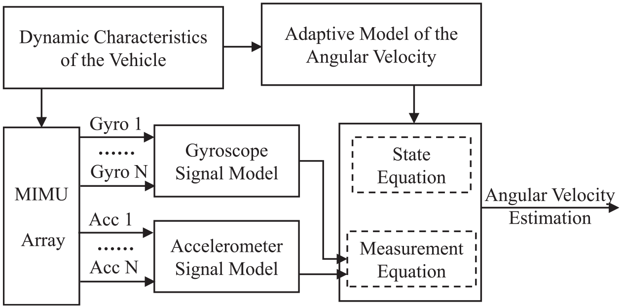
Block diagram of the proposed angular velocity fusion method of the MIMU array.
Accelerometer and gyroscope signal model of the MIMU array
The derivation of the signal model takes its starting point in the, from classical mechanics obtained, relationship between forces in rotating coordinate frames. The specific force in one point of a rotating coordinate frame should be decomposed into that of another point, a centrifugal term, and an Euler term as illustrated in Figure 2.
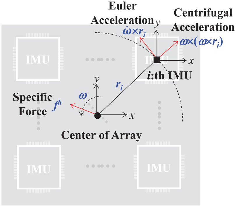
The decomposition of the specific force sensed by an accelerometer in the MIMU array.
The ideal specific force
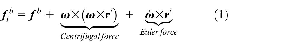
where

Considering the measurement noise of the accelerometer, we can mark the ith accelerometer as

where
The gyroscope measurement vector in the array frame is marked as

MLE-based fusion method
On the basis of the accelerometer and gyroscope signal model in equations (4) and (5), they can be combined and rewritten as the form shown in equation (5)

where
Seen from equation (5), the relationship between the angular velocity
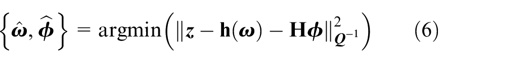
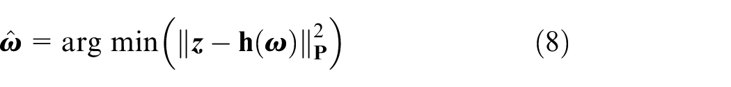
To solve
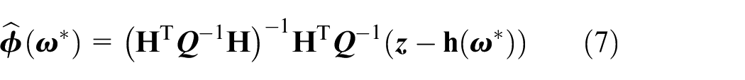
Then, the MLE of
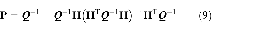
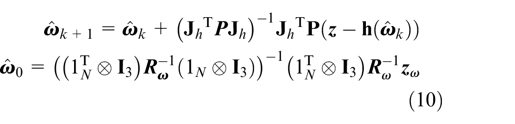
For solving
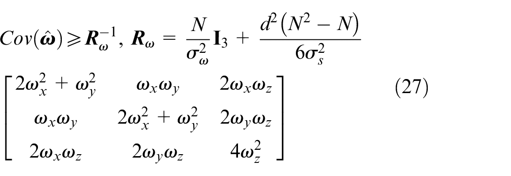
The Cramer–Rao bound (CRB) of
and
The MLE method based on Newton iteration can effectively fuse the redundant output of gyroscopes and accelerometers in the MIMU array, but Skog et al. 30 point out that the above method can only achieve the sub-optimal fusion performance. To further improve the fusion accuracy of the angular velocity of the MIMU array, section “Angular velocity estimation based on EKF with correlated system noises” proposes an optimized EKF-based fusion method.
Angular velocity estimation based on EKF with correlated system noises
In the MIMU array, because the accelerometer signal model has a non-linear relationship with the angular velocity (seen in equation (2)), an EKF-based fusion method to estimate the angular velocity is proposed in this section.
State and measurement equations building for estimating the angular velocity
According to the kinetic characteristics, the relationship between

On the basis of equation (11), the state equation for estimating the angular velocity

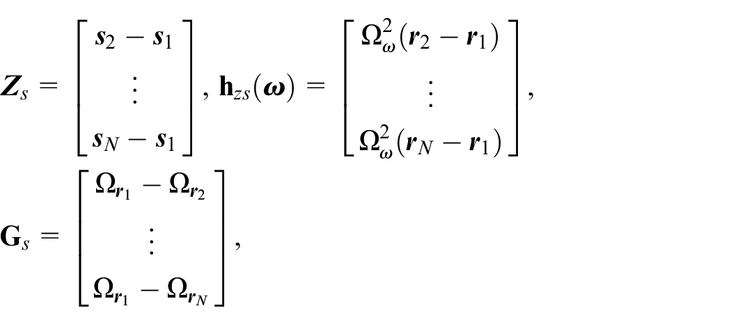
The relationship between the specific force


Equation (15) can be obtained by subtracting equation (14) from equation (13)

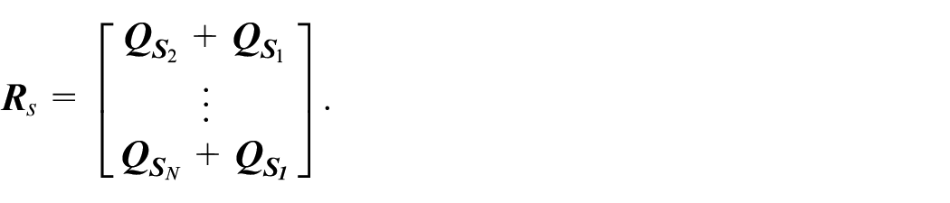
When measurement errors

where
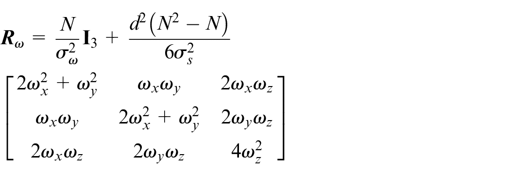
and the variance matrix of
Then, by combining equations (4) and (16), the measurement equation of the angular velocity
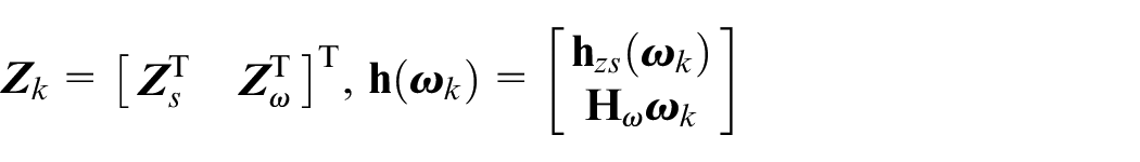
and the covariance matrix

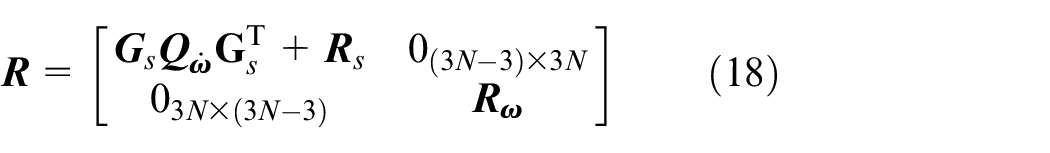
It can be seen from equation (18) that
Estimation process of the angular velocity based on the optimized EKF
When the state noise is related to the measurement noise, the general form of EKF equation has been derived.
31
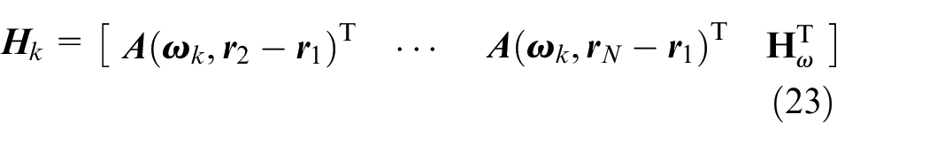
Thus, on the basis of the state and measurement equation built in equations (12) and (17), we can further derive the optimized EKF equation when the state and measurement noises are correlated. The recursive formula of one-step prediction
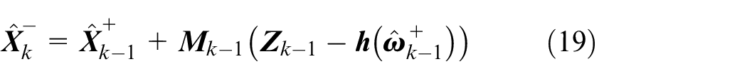

The state estimation
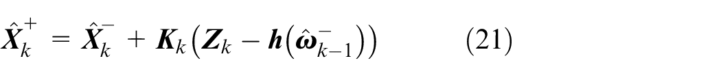
where
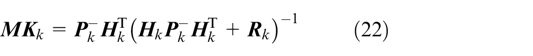
The calculation formula of one-step prediction

Thus, based on equations (19)–(26), the angular velocity can be estimated through optimized EKF. Seen from the derivation, the condition for deriving MIMU fusion models of the MIMU array is that the MIMU is of the same type, that is,
Experiments and analysis
To analyze the performance of our proposed method in section “Angular velocity estimation based on EKF with correlated system noises,” we simulate some typical angular maneuvers to generate the signal measurement of gyroscopes and accelerometers on the MIMU and compare the angular velocity estimation with that of the MLE method. Then, the kinematic vehicle experiments are also designed to verify the performance of the proposed method further.
Simulation experiments and analysis
Simulation experiments
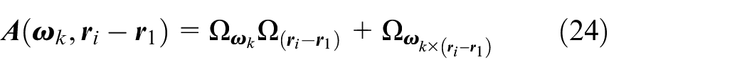
In the experiments, we simulate an MIMU array composed of 16 inertial sensors, and its spatial layout is shown in Figure 3. The principle of selecting the number of MIMU on the array is analyzed in Chapter 5 of Xing. 31 When the number of MIMU on the array is not less than 4, the parallel symmetry and skew layout have similar reliability and accuracy. While the more sensors there are, the more advantages of parallel symmetrical layout in terms of volume and design complexity. So the simulation experiments design the array with 16 MIMUs.
The layout of the simulated MIMU array.
The angular motion patterns can be abstracted into two types: (1) constant angular rate and (2) change-in-time angular velocity with variable frequency and amplitude. Meanwhile, in some specific motions with large angular rates, the gyroscopes would be out of the measurement range due to intense angular motions. Thus, the simulation experiment with change-in-time angular velocity also includes the large angular rate at some points in time. The ideal triaxial angular velocities within different time periods are shown in Table 1.
Ideal triaxial angular velocity within different time periods.
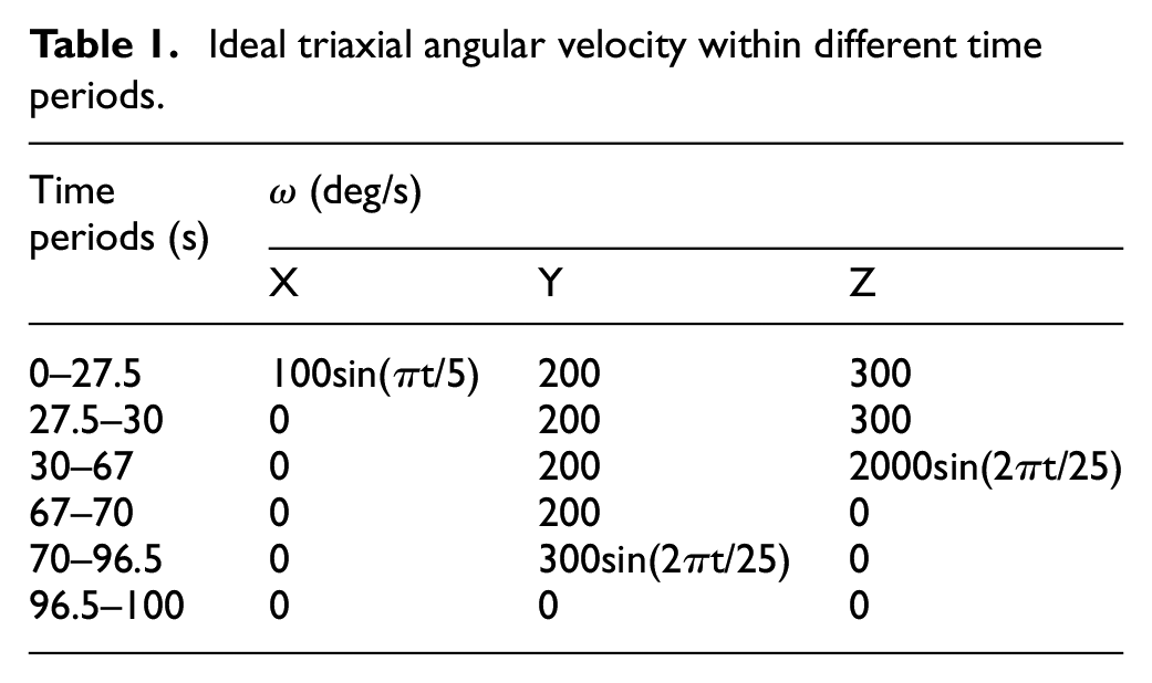
In the experiments, the line motion is set to a uniform linear motion.
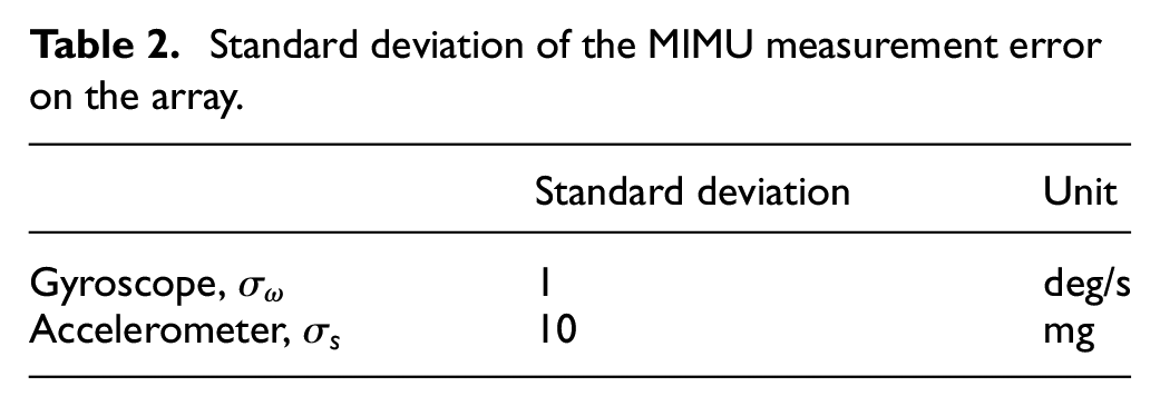
The distance between each two MIMUs is d = 1 cm in Figure 3. The measurement error’s standard deviations of the gyroscope and accelerometer on the array are shown in Table 2, and the measurement range of gyroscope is set as ±1500 deg/s.
Standard deviation of the MIMU measurement error on the array.
The simulated triaxial outputs and Z-axis local amplification of gyroscopes on the MIMU array are shown in Figure 4. The numerals 1–16 in the Z-axis local amplification of Figure 4 represent the number of MIMU in Figure 3. It can be seen from Figure 4 that the angular rate cannot be measured accurately when it is larger than the gyroscope measurement range 1500 deg/s.
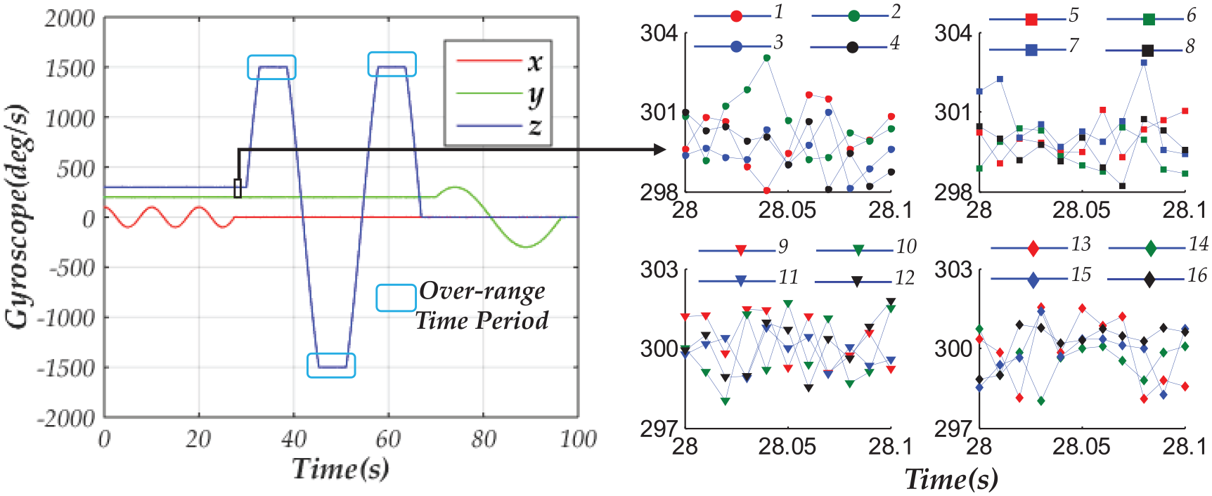
Triaxial outputs and Z-axis local amplification of gyroscopes on the MIMU array.
Based on the simulated original data of the gyroscopes and accelerometers in Figures 4 and 5, the angular velocity fused results of our proposed method are analyzed in section “Simulation results analysis.”
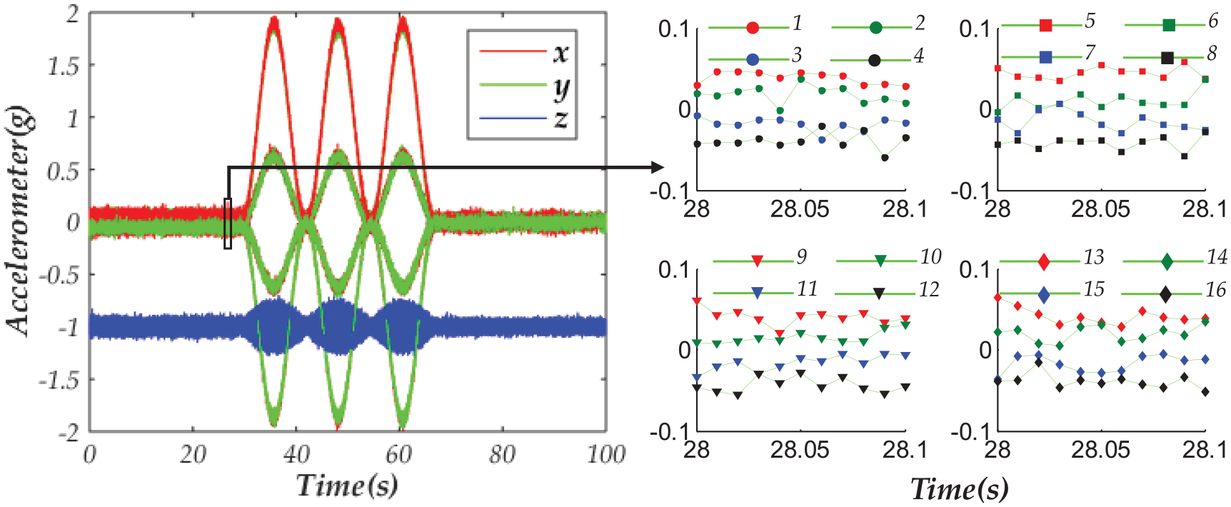
Triaxial outputs and Y-axis local amplification of accelerometers on the MIMU array.
The simulated triaxial outputs and Y-axis local amplification of accelerometers on the MIMU array are shown in Figure 5. Although the speed is set to be unchanged in the experiments, that is to say, the ideal specific force at the center of the array should be [0, 0, −g], the outputs of accelerometers on the same axis change with time. For instance, the outputs of accelerometers on the same axis vary between 30 and 70 s in Figure 4. The reason is that the measurement of each accelerometer on the array is comprehensively affected by the angular velocity and angular acceleration as shown in equation (1) of section “Angular velocity fusion method of the MIMU array.”
Simulation results analysis
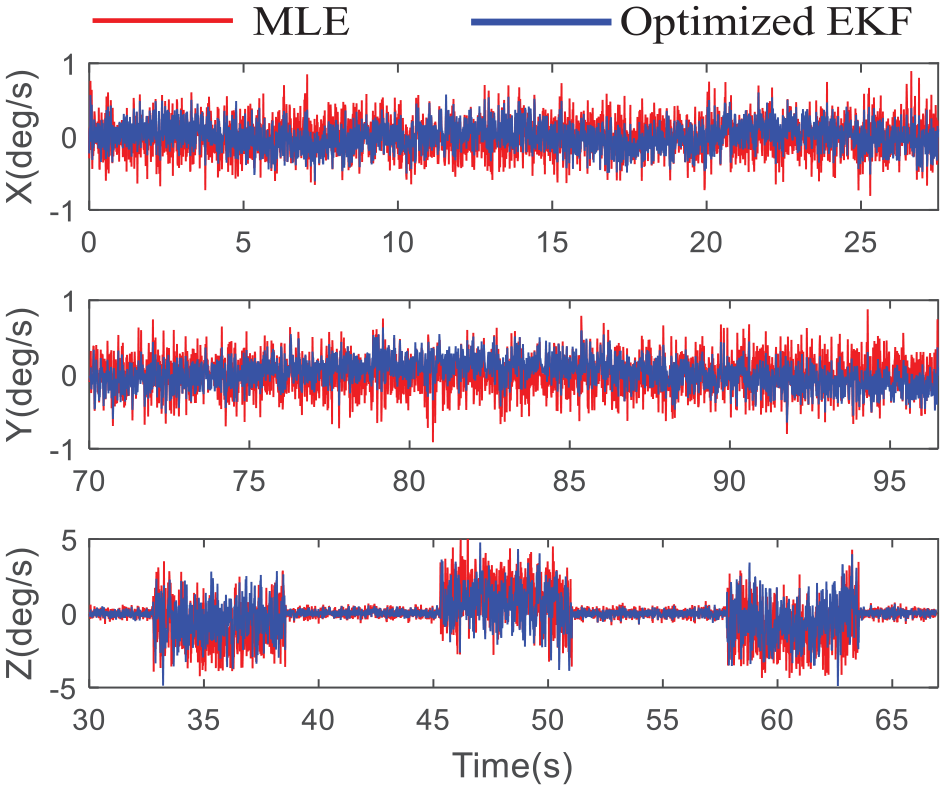
In this section, the traditional MLE and the proposed method based on the optimized EKF are, respectively, applied to estimate the angular velocity . The comparisons of the estimated angular rates with different methods are shown in Figures 6–8.
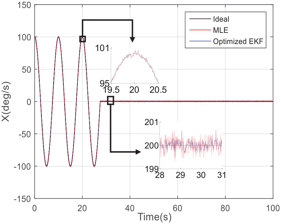
Comparison of the X-axis angular rate.
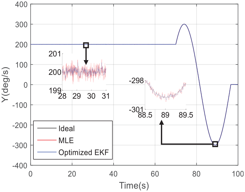
Comparison of the Y-axis angular rate.
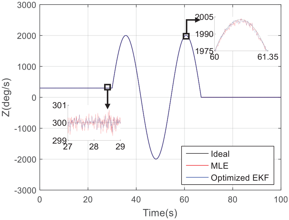
Comparison of the Z-axis angular rate.
It can be seen from Figures 6–8 that the triaxial angular rate can be estimated regardless of how high the frequency is and how large the amplitude is. This because the established estimation model of the angular velocity in equation (11) can be adjusted adaptively. The frequency of
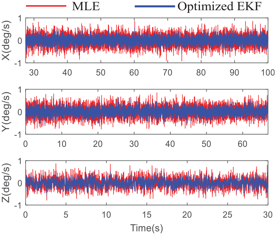
Angular velocity estimation errors under the condition of constant angular rates.
Angular velocity estimation errors under the condition of change-in-time angular rates.
In addition, the root mean square errors (RMSE) of the estimated angular rates are calculated from the Monte Carlo simulation experiments. 24 Table 3 shows the RMSE comparison of MLE and optimized EKF under the condition of constant angular rates.
RMSE of the angular velocity under the condition of constant angular rates.
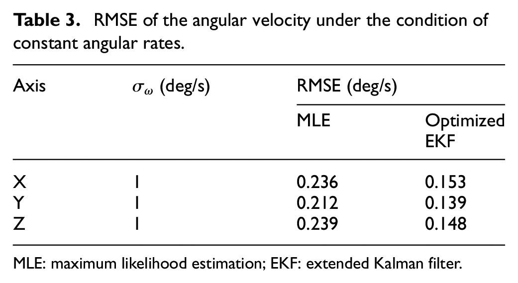
MLE: maximum likelihood estimation; EKF: extended Kalman filter.
Table 4 shows the RMSE comparison of the two methods under the condition of change-in-time angular rates.
RMSE of the angular velocity under the condition of change-in-time angular rates.
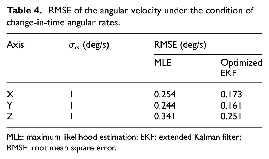
MLE: maximum likelihood estimation; EKF: extended Kalman filter; RMSE: root mean square error.
In section “MLE-based fusion method,” it is analyzed that after fusing the measurements of gyroscopes and accelerometers on the MIMU array, the CRB of the estimated angular meets the formula as shown in equation (27), that is to say, the minimum RMSE of the estimated angular rate can be smaller than
Moreover, it can be seen from Tables 3 and 4 that the optimized EKF-based estimation method proposed in the paper can adaptively adjust the angular velocity model according to the dynamic characteristics, so its angular rate estimation accuracy can be increased by about 1.5 times compared to the MLE method.
Kinematic vehicle experiments and results
In this section, the kinematic vehicle experiment was designed based on an in-house designed MIMU array and the fiber optic strapdown inertial navigation system (SPAN-CPT). The gyroscope outputs of SPAN-CPT were collected as the comparison of that of the MIMU array, so as to evaluate the proposed angular velocity fusion method of the MIMU array. The in-house designed MIMU array is shown in Figure 11.
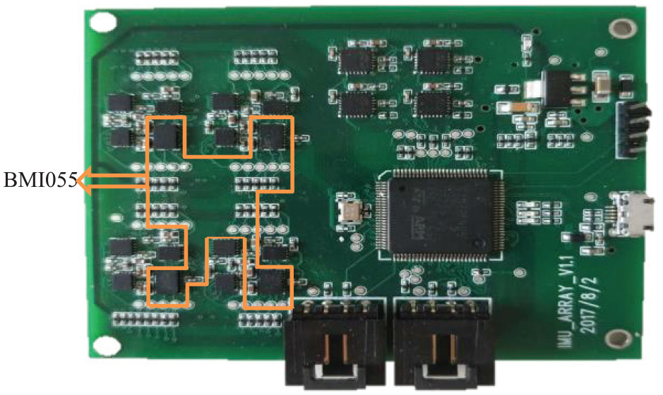
In-house designed MIMU array.
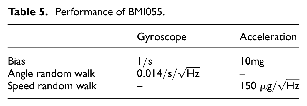
Five different types of MIMUs are integrated on the MIMU array to conduct the extended research and validation of the data fusion of the MIMU array. Due to the angular velocity fusion method proposed in this paper which is based on the redundant output of the same type of MIMU, we chose one type of MIMU for analysis in the kinematic vehicle experiments. Before the kinematic vehicle experiment, the temperature experiment, vibration experiment, and zero bias repeatability experiment were carried out for the five different types of MIMUs. Then through the above performance test experiments, it is concluded that the performance of BMI055 is the best. Therefore, the outputs of BMI055 on the array were used to estimate the angular velocity fusion in the experiment. The layout of BMI055 on the MIMU array is shown in Figure 11, and the performance index parameters of its gyroscopes and accelerometers are shown in Table 5. In Figure 11, the data of BMI055 on the MIMU array were collected by the integrated advanced RISC machine (ARM) processor and stored in real time in the TF card on the back of the module. Through the designed verified software, the data stored in the TF card are read to verify the angular velocity fusion method.
Performance of BMI055.
To compare and analyze the performance of the algorithm, the output of the fiber-optic gyroscope in Novatel’s SPAN-CPT integrated navigation system was selected as the comparison benchmark in the experiment. The kinematic vehicle experimental system based on the independently designed MIMU array and the SPAN-CPT integrated navigation system is shown in Figure 12. The SPAN-CPT system could directly use the +13-V DC power provided by the vehicle system.
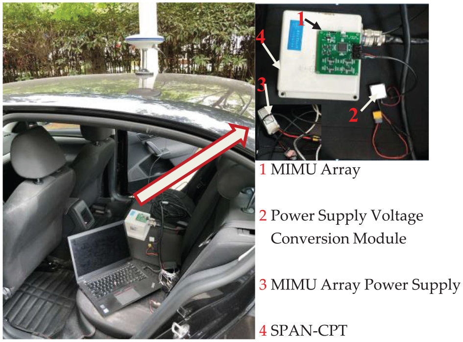
Kinematic vehicle experiments systems.
Kinematic vehicle experiments
In total, 350 s of data were totally collected in the sports car experiment. The driving track and the vehicle status measured by the SPAN-CPT integrated navigation system in the experiment are shown in Figure 13. It can be seen from the figure that the sports car’s driving track is several rounds around a triangular area. In the attitude curve, in addition to the maneuvering changes in course, the horizontal rolling and pitching directions also have a small fluctuation in a certain range due to the sway of the car body and the road fluctuating.
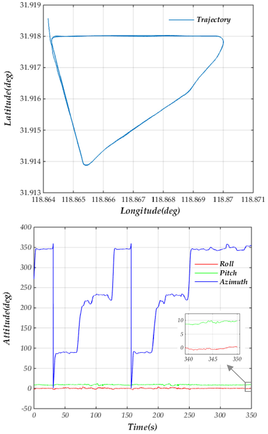
Trajectory and attitude in the kinematic vehicle experiment.
The definition of the coordinates of the MIMU array is shown in Figure 14. The coordinates of BMI055 marked as A in the figure are
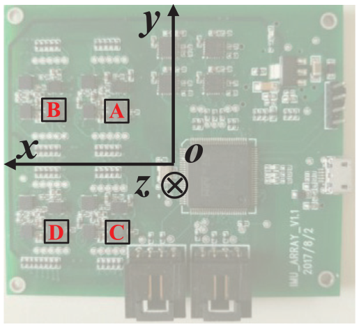
Coordinate frame of the MIMU array.
The outputs of the gyroscopes and accelerometers of the four BMI055s in Figure 14 and their partial enlarged diagrams are shown in Figures 15 and 16.
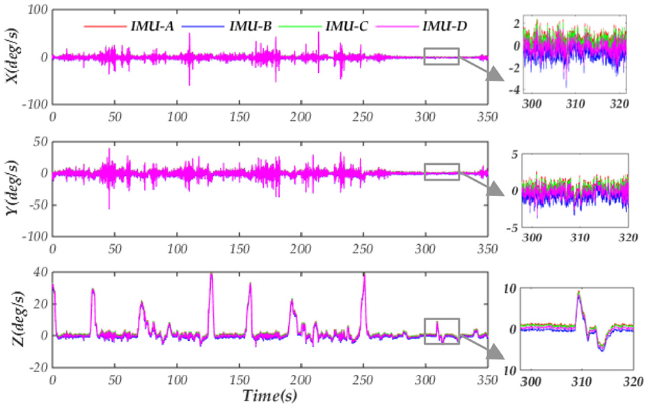
Gyroscope outputs of BMI055 on the array.
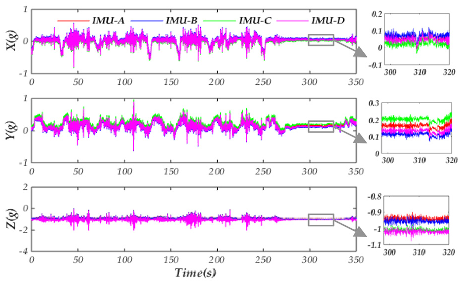
Accelerometer outputs of BMI055 on the array.
After deducting the bias of the gyroscopes and accelerometers in the BMI055 array shown in Figures 15 and 16, the angular velocity fusion method of the MIMU array proposed in the paper and the traditional MLE method are, respectively, used to estimate the angular velocity measured by BMI055, and the results are analyzed in section “Results analysis.”
Results analysis
The fused angular velocity result is compared with the outputs of the gyroscopes, in the SPAN-CPT, with the bias deducted, which acts as the data comparison benchmark when comparing the RMSE of the fused angular velocity by two fusion methods. The result is shown in Table 6. After analyzing the data shown in Table 6, it can be seen from the result that the measurement accuracy of the fused angular velocity of MIMU array is about two times higher than that of a single gyroscope, while it is consistent with the theoretical analysis and simulation result. Compared with the traditional MLE method, the angular velocity fusion method proposed in this paper has improved its accuracy by about 1.5 times. As is shown in the above analysis results, the sports car experiment validated that the angular velocity fusion method of MIMU array proposed in this paper can further improve the angular velocity estimation accuracy.
RMSE of the fused angular velocity by different fusion methods of the MIMU array.
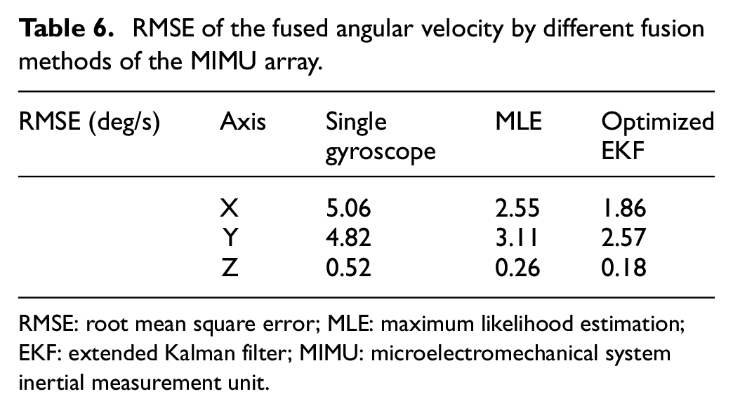
RMSE: root mean square error; MLE: maximum likelihood estimation; EKF: extended Kalman filter; MIMU: microelectromechanical system inertial measurement unit.
Conclusion
In this study, the MIMU array is applied to provide the angular velocity for the vehicles, such as the multi-motor UAV and the car. In the MIMU array, the angular velocity can be measured not only by redundant MEMS gyroscopes but also by the accelerometers spatially distributed on the array, thus the accuracy can be improved and the range can be broadened simultaneously. To get more optimal estimation performance of the angular velocity, an optimized EKF with correlated system noises is proposed and demonstrated by the simulation experiments and kinematic vehicle experiments that the accuracy can be increased by about 1.5 times compared to the traditional MLE method.
This contribution has the following innovations: (1) According to the kinetic characteristics of the vehicles, an adaptive estimation model of the angular velocity is built as the state equation, and the signal models of the MIMU array are considered as the measurement equation, thus the angular rates with arbitrary magnitudes can be estimated; (2) By optimizing the traditional EKF equations, the angular velocity of MIMU array can be estimated even in the filter equations, where the state and measurement noises are correlated.
There are some further researches in the future work: (1) This method has to be demonstrated more adequately in the actual flight experiments of the UAV. Due to the limitation of experimental conditions and considering the reliability and safety of flight experiments on multi-rotor UAV, there are no conditions for flight experiments at present. The algorithm will be verified by more reliable experiments on the ground before flight experiments. (2) In the actual flight experiments, how to adjust the angular acceleration in the state equation according to the complicated maneuvers is a problem worth further analysis.
Footnotes
Acknowledgements
The authors thank the anonymous reviewers for their valuable comments and critical remarks, which greatly improved the quality of the manuscript.
Declaration of conflicting interests
The author(s) declared no potential conflicts of interest with respect to the research, authorship, and/or publication of this article.
Funding
The author(s) disclosed receipt of the following financial support for the research, authorship, and/or publication of this article: This work was supported in part by the National Natural Science Foundation of China (Grant Nos. 61304227 and 61903241) and the China Postdoctoral Foundation (Grant No. 2018M630424).