
Abstract
In order to realize the tram’s low-floor structure, most of the trams that have been recently introduced adopt an independently rotating wheelset. In the case of trains driving in two regions with different gauges, an independently rotating wheelset may be applied to utilize the variable track technology. Since the independent rotation type wheelset has no rotational restraint of the left and right wheels, the difference in rotational speed between the outer and inner wheels occurs naturally during curved driving, and it is applied to railroad vehicles traveling in sharp curve sections because it smoothly drives curved driving. However, the longitudinal creep force and the lateral restoring force are weakened as the left and right rotational constraints disappear. Lack of lateral direction restoring force weakens stability while causing continuous flange contact driving or zigzag phenomenon against disturbance. Under the conditions of driving in a sharp curve, these railway vehicles generate excessive wear, noise, and lateral pressure, as well as deterioration of ride comfort and derailment. In order to overcome these drawbacks, a method has been proposed in which the torque of a motor mounted on each wheel is individually controlled to generate lateral restoring force or to improve driving performance through lateral displacement control using a yaw moment. In this paper, development using HIL (hardware in the loop) simulator was performed to check the performance and stability of the individual motor torque control technology before verifying by applying the individual motor torque control to the actual vehicle. HIL simulator were constructed by combining a real-time dynamic analysis model of a railway vehicle with a drive motor to which real individual motor control was applied. Under the conditions of driving the test track where the actual test vehicle was tested, the analysis of the driving characteristics and the control characteristics of the disturbance was performed to confirm the proposed individual motor torque control performance.
Keywords
Introduction
The independently rotating wheelset can make the low floor structure of the vehicle by eliminating the axle connecting the left and right wheels. The recently introduced tram is introducing a 100% low-floor vehicle to take care of the transportation handicapped persons. Since the rotational restraint force between the left and right wheel disappears, a rotational speed difference between the inner and outer wheels occurs during a curved driving, which enables natural curved driving. However, the longitudinal creep force and the lateral restoring force, which are inherent characteristics of the railway vehicle generated by the left and right wheel restraint, disappear. Because of the lack of resilience against disturbances, continual flange contact or zigzag repeatedly impacting the left and right flanges may occur.1,2 In order to overcome the shortcomings of the independent drive type wheelset, various studies have been conducted for guidance control and steering control, but it was difficult to put it into practical use due to the addition of complex mechanisms such as additional sensors or link mechanisms, resulting in increased manufacturing cost or difficulty in maintenance. On the other hand, in the case of a traveling bogie, it is possible to overcome the shortcomings through control using individual torque control mounted on each wheel. Individual motor control does not require additional sensors or devices and can be applied by simply changing the control method of the motor, so it is easy to put into practice. It is possible to plan routes with high profitability and high operational efficiency through the densely populated areas in the city center or through key commercial areas. This paper describes the technology verification using HIL simulator composed by connecting a real-time vehicle analysis model and a motor to which a real individual torque is applied before performing a driving test by applying the individual motor torque control (ITC) of the developed independent driving wheelset to a real vehicle. In particular, the superiority of individual motor control based on yaw angle compared to the previously proposed lateral displacement based control was verified through the test results. The real-time vehicle analysis model was developed based on the modified dynamic model of the independently rotating railway vehicle proposed by Cho and Kwack. 3
In order to perform verification of the developed individual motor control technology, a small-scale driving test stand was produced, and Ahn et al., 4 Oh et al., 5 and Won et al. 6 were verified through various developed algorithms through a test using the manufactured small-scale roller rig driving test stand. Various individual motor control technologies for improving the performance of independently rotating wheel type railway vehicles have been developed through simulations and small-scale tests as research subjects of many researchers such as Mei, Dukkipati, Goodall, Perez, etc.7–11
HIL simulator configurations
HIL simulator has been developed and used for the purpose of reducing the risk in the nuclear industry and the aerospace industry, where it is difficult to manufacture actual test vehicles. In addition, HIL simulator is widely used in various industries because it can perform evaluation of various test conditions with high reliability in a short time.12–15 Due to the reliability of HIL simulator and the shortening of the development period, the most research cases in the automotive industry have been published.16–24 As the automobile industry is advanced, various control functions are added and HIL simulator is the most widely applied industrial field to reflect it in products. In the case of railroad vehicles, HIL simulator has been actively applied to reduce the risk of developing new technologies and applying them to actual vehicles to verify performance.25–28 HIL simulator are often used to evaluate real-world development or controller prototypes using fast computing devices and highly reliable real-time analysis models. To construct HIL simulation for verification of individual motor torque control technology to improve the driving performance of railroad vehicles using the independently rotating wheelset proposed in this paper, it is necessary to secure highly reliable real-time vehicle analysis model. MIL (Model In the Loop) simulation for real-time evaluation by applying a control algorithm to an analytical model for a real-time analysis model, SIL (Software In the Loop) simulation for evaluating software by coding a control algorithm, and real-time development parts or objects. It is also classified and used in HIL simulator, which is evaluated in connection with an analytical model.
In this paper, the development of a highly reliable real-time analysis model and the hardware configuration capable of real-time calculation are described, and HIL simulator are constructed by preparing individual motors and individual motor controllers to be applied to test vehicles in advance. The analysis model was composed of 26 degrees of freedom model based on Matlab, and HIL simulator was constructed using dSPACE’s SCALEXIO platform, which is the fastest, latest and reliable with the most market share.
Real-time analysis model
The test vehicle consists of a three-car combination as shown in Figure 1. The driving bogie is applied to the leading vehicle and the trailer bogie is applied to the rear vehicle. The intermediate vehicle is bound to the front and rear vehicles with a coupler and operates in the air. In general, a five-car tram that is in operation is a three-bogies support system, and the test vehicle proposed in this paper is designed to perform a function equivalent to 1/2 of a five-module standard vehicle. The developed system can be applied to three-car trains as well as five-car trains.
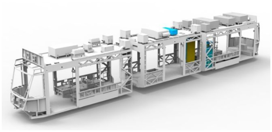
Test vehicle applied with developed ITC technology on 100% low floor tram structure.
In the driving bogie, the clearance between the motor and the driving gear is limited, so the desired steering angle cannot be applied when driving a sharp curve. On the other hand, since the trailer bogie is not equipped with a motor, a steering device can be applied to apply a steering angle equivalent to a radial steering when driving a sharp curve. Active steering control can be applied to the trailer bogie, but since driving bogie is difficult to apply to the active steering control, individual motor torque control technology using motor torque control has been developed.
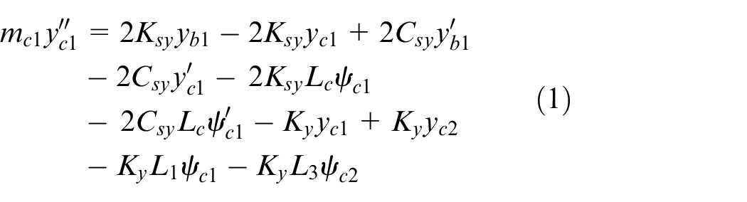
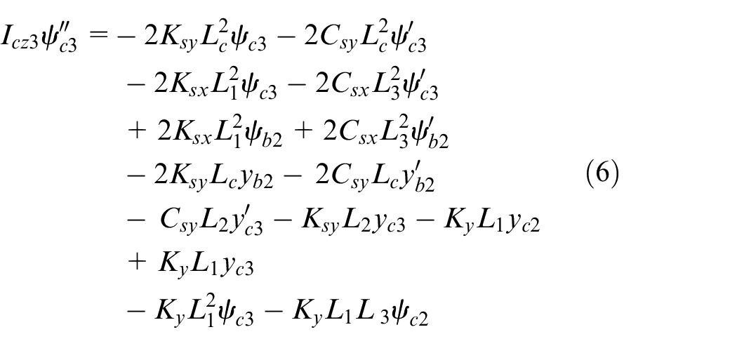
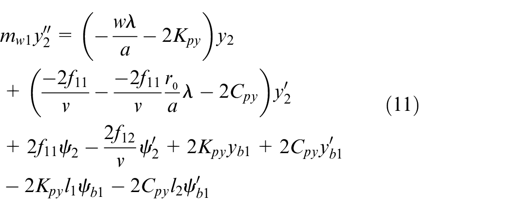
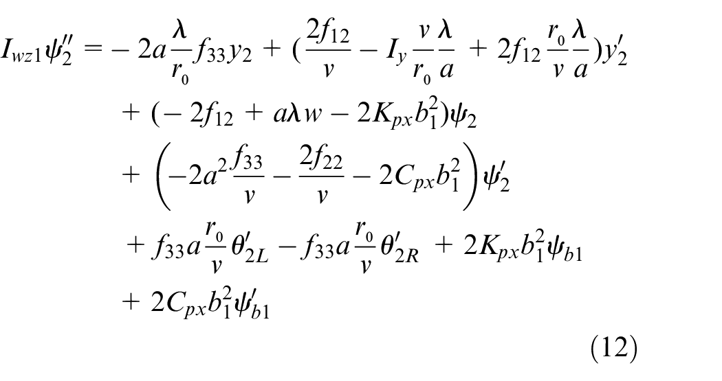
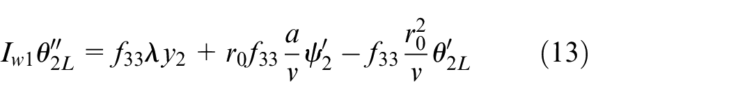
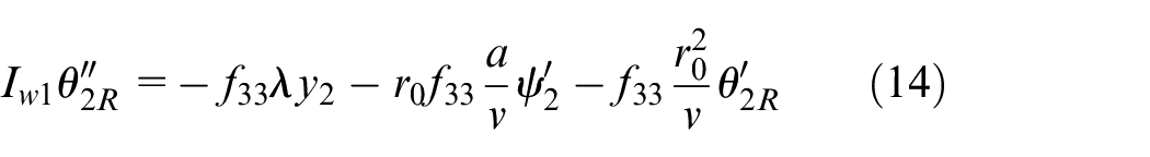
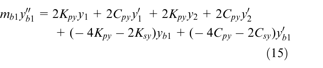
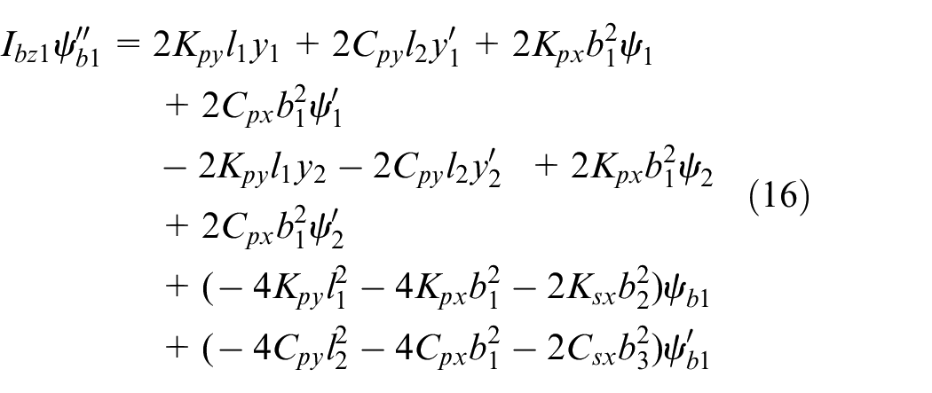
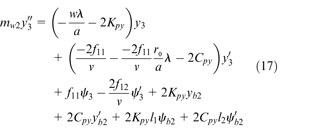
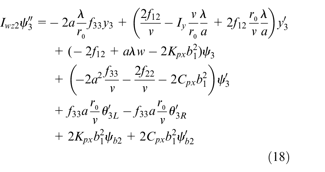
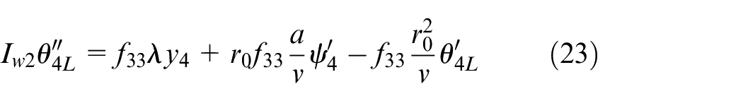
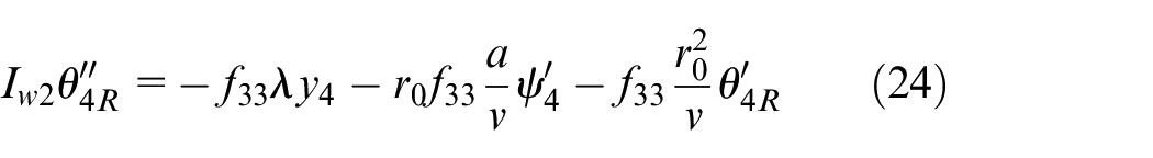
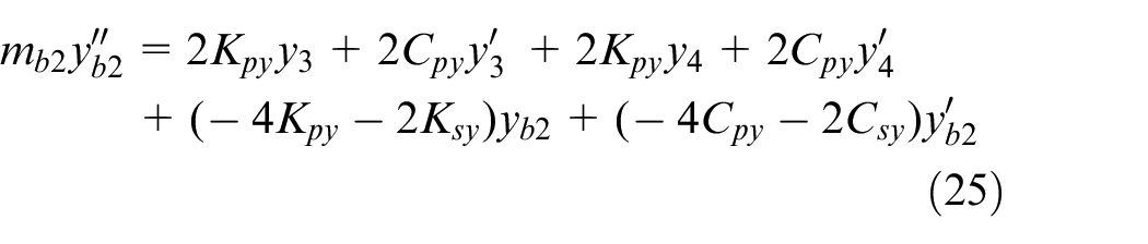
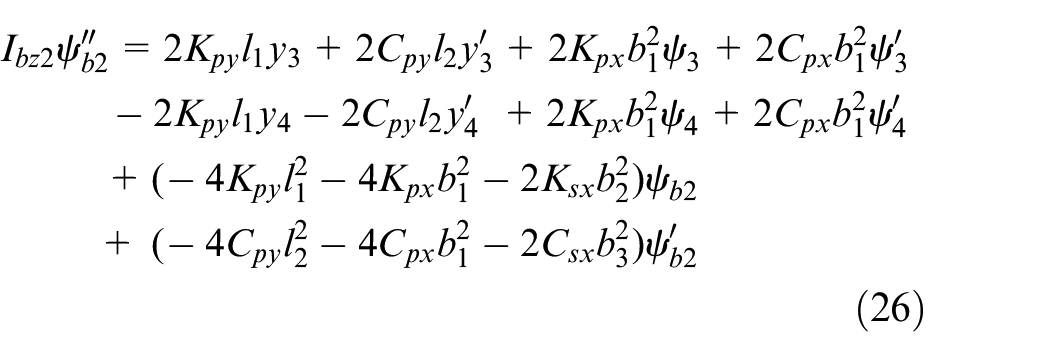
In this paper, in order to verify the individual motor torque control technology applied to the driving bogie using HIL simulator, the 26-degree real-time test of a three-car train test vehicle that adds rotational freedom of the left and right wheels to apply control torque to each wheel of the drive bogie An analytical model was developed. The real-time analysis model linearizes most of the nonlinear elements to enable quick calculation without compromising the accuracy of the analysis, and simplifies the real-time analysis model with equations (1)–(26) through some assumptions. Figures 2 and 3 are analysis model of a test vehicle for real-time analysis model development. When the analysis is performed by considering the three vehicles as a three-section link, it is possible to obtain an analytically correct solution, but it is difficult to guarantee real-time analysis because the formula is complicated and the amount of calculation is increased. In this paper, instead of the link structure, the lateral stiffness model for the joint is added to simplify the equation to predict the behavior of the three-dimensional analysis model as a resultant force model. Six motion equations were derived, taking into account only the degrees of freedom for lateral displacement and yaw displacement for a three-car body. The equations of motion for bogies and wheelsets are independent of vehicle organization, so the equations of motion for the analysis of the curves of the existing independent drive railroad vehicles have been applied.
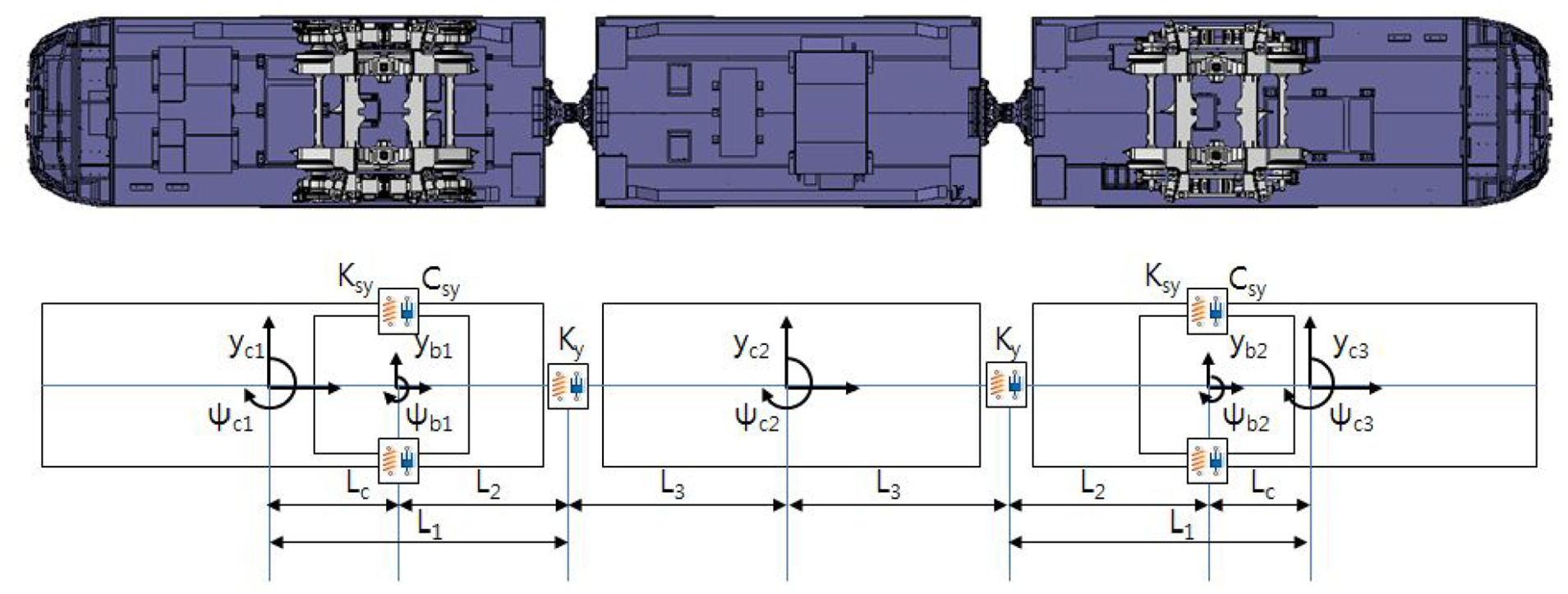
Test vehicle applied with developed ITC technology.
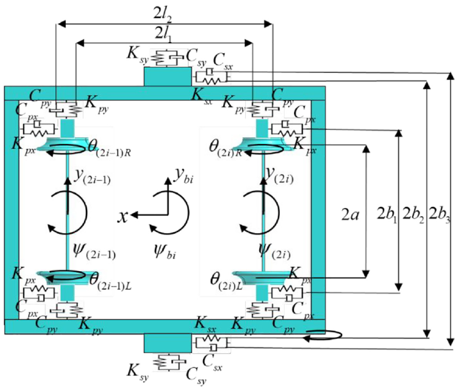
Bogie analysis model with independently rotating wheelset (Leading bogie i = 1, Trailer bogie i = 2).
A real-time analysis model was developed to perform the steering performance verification analysis of the test vehicle using HIL simulator. After creating an analysis model using Simulink for a 26-degree-of-freedom analysis model consisting of four wheelsets, two bogies, and three car bodies, it was confirmed that the analysis was normally performed by performing continuous time analysis using a variable step integrator. dSPACE’s SCALEXIO computation equipment being introduced for real-time analysis guarantees real-time analysis performance up to an integral step of 10 µs with discrete time analysis. By performing the discrete time analysis using a fixed step integrator on the program created using the developed analysis model, it was confirmed that the analysis is normally performed under the condition that the integration step is greater than 10 µs.
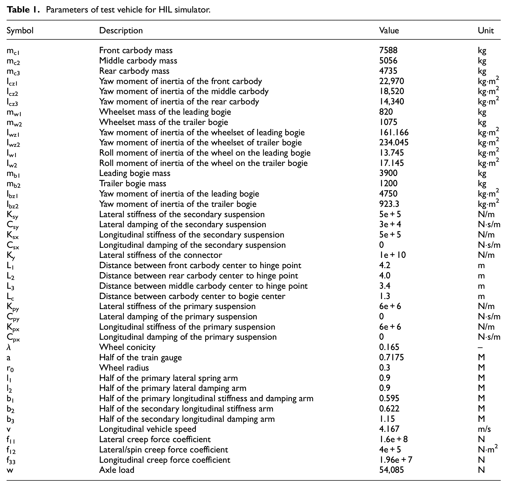
The variables used in the formula are summarized and displayed in Table 1.
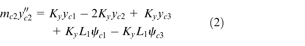
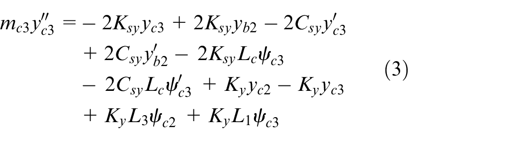
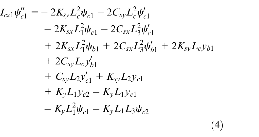
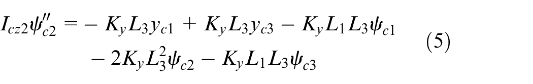
Carbody equation
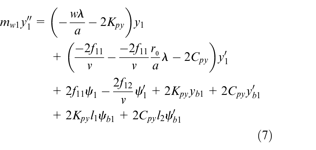
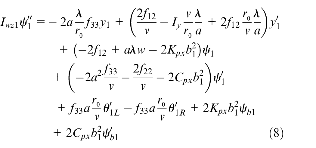
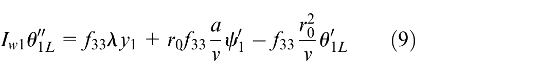
Front wheelset equations of leading bogie

Rear wheelset equations of leading bogie
Leading bogie equations
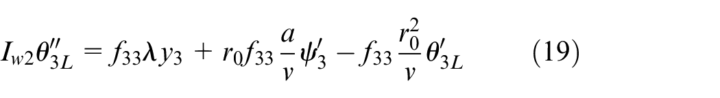
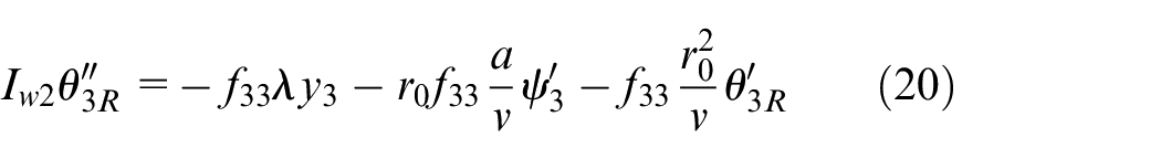
Front wheelset equations of trailer bogie
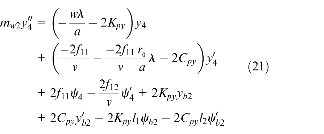
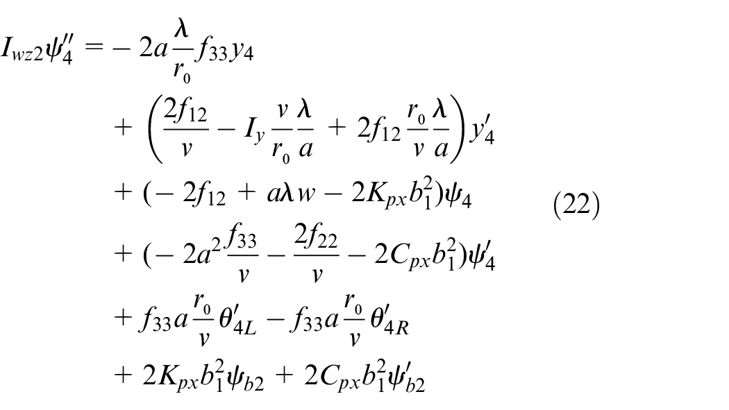
Rear wheelset equations of trailer bogie
Trailer bogie equations
Parameters of test vehicle for HIL simulator.
Motor and motor controller
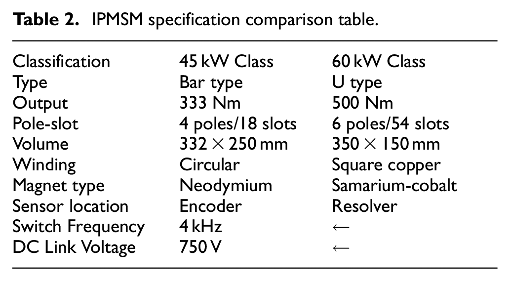
A permanent magnet synchronous motor (PMSM) with excellent torque control responsiveness was developed and applied to test vehicles. In order to secure the margin of the control torque excluding the driving force in the driving motor, the power was increased compared to the existing motor, and the specification was changed to a 60 kW class motor (Existing PMSM is 45 kW) (Table 2).
IPMSM specification comparison table.
The output characteristics of an ITC (Individual Torque Control) motor is shown in Figure 4. The maximum output occurs in a constant output range of 1400 rpm to 2400 rpm, and it exhibits high-speed characteristics in the range of 2400 rpm to 4450 rpm. The design was conducted based on three points of 500 Nm @ 1400 rpm, 290 Nm @ 2400 rpm, and 90 Nm @ 4450 rpm on the graph. The section views of the 45 kW class-Bar type IPMSM before the design change and the 60 kW class-U type IPMSM after the change are also displayed in Figure 5. The main design change was that the required torque increased by approximately 50% from 333 Nm @ 1400 rpm to 500 Nm @ 1400 rpm. As the sensing method of mounting the encoder on the outside was changed to the method of inserting the resolver into the motor, the stacking length effective for the motor output was reduced. Therefore, the design for improving the power should be considered.
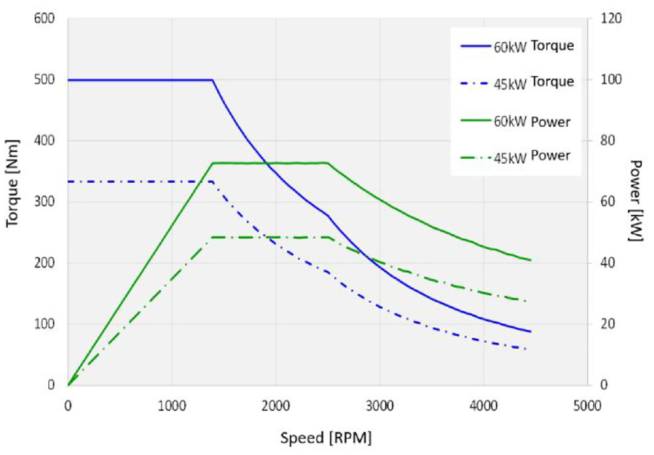
Comparison of the output specifications of the newly designed PMSM and the existing PMSM.
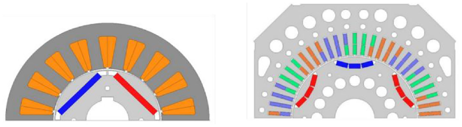
Left: 45 kW class-Bar type IPMSM. Right: 60 kW class-U type IPMSM.
The pole-slot number combination of the motor was changed from 4 poles 18 slots to 6 poles 54 slots to improve torque and obtain sine counter electromotive force. The winding was designed as a square copper wire that can increase the area of the winding to improve the motor output in the existing circular wire. The permanent magnet type was changed to samarium-cobalt, which is superior in price and thermal properties to neodymium. Table 1 shows the major design changes of IPMSM.
Compositions of HIL simulator
HIL simulator replaces the test object with a virtual analysis model when it is difficult to secure the actual test object or when a risk is involved in the test, and the development part of interest is composed of a real product. It is possible to conduct product development and evaluation in a more realistic environment through testing using a mutual response relationship between a real product and a real-time virtual analysis model.
In this paper, to verify the performance of the lateral displacement and yaw angle control system using the individual motor torque control under development, a HIL simulator environment was constructed and the controller performance was evaluated. The first thing to consider in establishing the HIL simulator environment is the reliability and speed of calculation equipment. The HIL simulator platform operating in the actual industrial field is mainly used by the platform using Opal-RT series, NI-PXI series, and dSPACE’s Autobox. Although it is relatively expensive in high-tech industries such as automobiles and aviation, dSPACE’s products are excellent in terms of reliability and computational speed. In this paper, considering this excellence, HIL simulator using SCALEXIO, a successor to dSPACE’s Autobox, was constructed. In order to run dSPACE’s SCALEXIO platform, a dedicated PC is required to run five types of software: Configuration desk, Control desk, Model desk, and Motion desk provided by Matlab of Mathworks and dSPACE. By adding a beam project to visualize the results of the motion desk that simulates the test results in real-time 3D graphics, an environment was built to perform the test while projecting it on a 100-inch screen to feel the driving of a real vehicle. The control PC and the SCALEXIO device are connected to each other through an ethernet cable, and the SCALEXIO device is connected to the hypertronic connector based on the predefined controller pin map information. In order to check the characteristics of the disturbance response to the real-time analysis model, a disturbance input device was connected. By adding a CAN information-based remote operation device, the speed is varied or an emergency stop signal is generated, and the function of turning the controller ON/OFF through mechanical switching is added. Figure 6 shows the HIL simulator system configured for ITC verification.
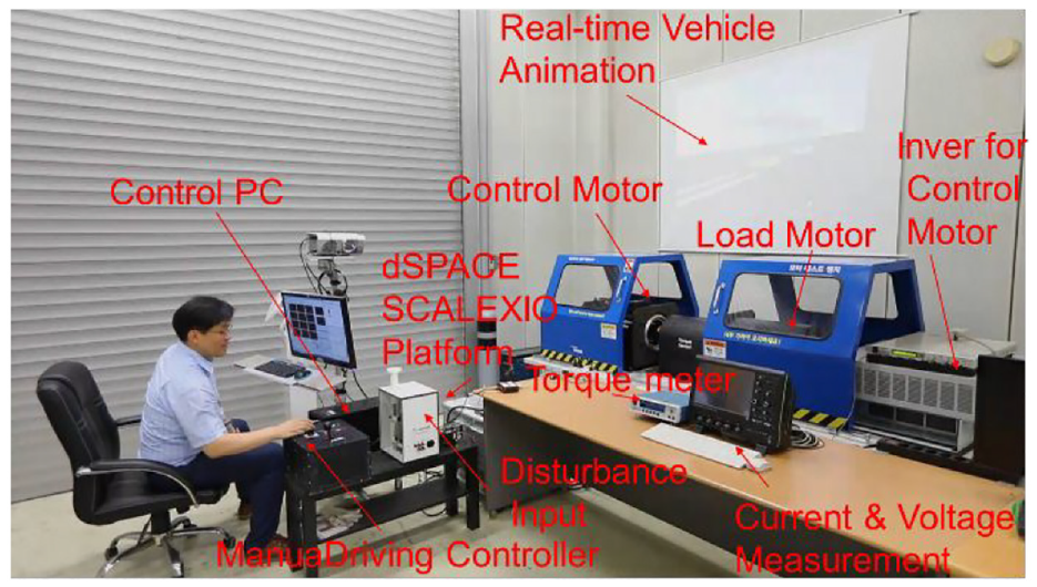
HIL simulator configured for ITC verification.
Establishment of controller verification HIL simulator
In order to establish a HIL simulator environment and perform full-scale testing, it is necessary to define a real-time driving analysis model to replace the actual test vehicle with Matlab/Simulink, and to define the analog output signal that converts the result of the analysis model into an electrical signal and delivers it to the controller.
The controller that receives the sensor signal extracted from the virtual test vehicle sends the calculated torque information to the inverter. The actual driving torque generated by driving the motor by the inverter is measured and transmitted back to the real-time analysis model, so the closed loop must be completed. In order to complete this series of test procedures, it is necessary to develop a program using five software such as Matlab, configuration desk, control desk, model desk, and motion desk.
Figures 7 and 8 are conceptual diagrams of the motor configuration of a driving bogie to which individual motor torque control is applied. Three of the four motors of the driving bogie are composed of a virtual model, and only one motor is configured with HIL simulator to evaluate the controller by applying a real motor. The configuration desk defines input and output signals, and the control desk uploads the compiled model to SCALEXIO and performs setup and monitoring to perform virtual driving test. Finally, the virtual test vehicle implements the 3D shape output information using the motion desk. Figure 9 shows various results calculated from the real-time analysis model on the control desk and measured signal values in a graph. In addition, various control input values are defined and monitored to control the actual controller and the virtual controller. Figure 10 shows the motion desk window that finally represents the performance of the virtual vehicle reflecting the driving characteristics of the controller and the actual motor in a test environment in a 3D graph.
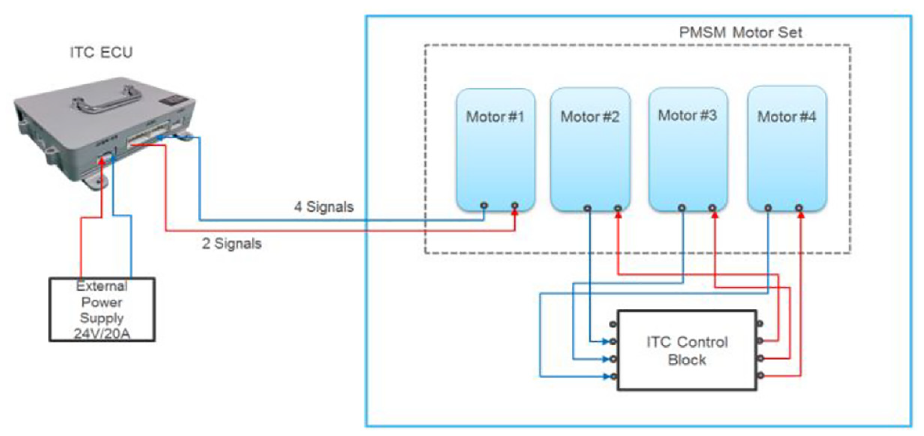
A conceptual diagram of the motor configuration for constructing a driving bogie to be applied to individual motor controllers in the HIL simulator environment.
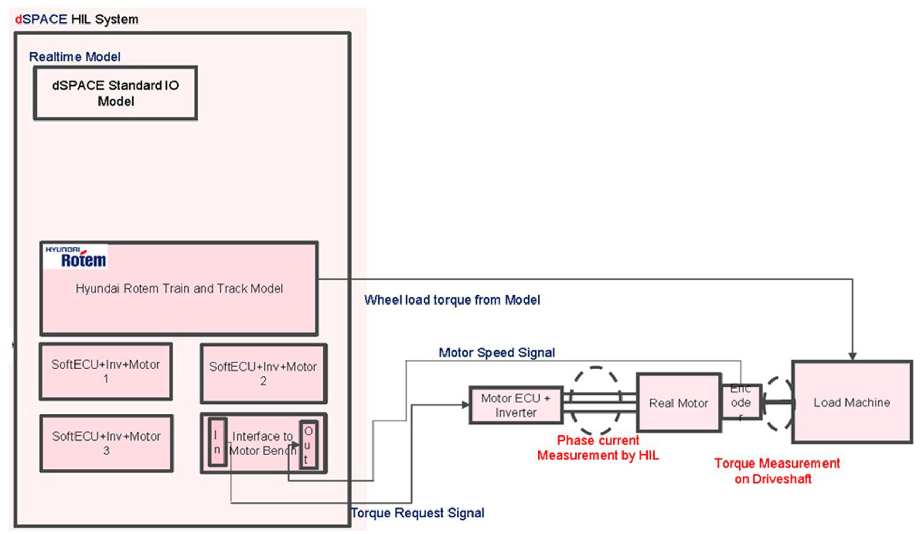
Virtual motor model and real motor signal connection configuration implemented in dSPACE platform.
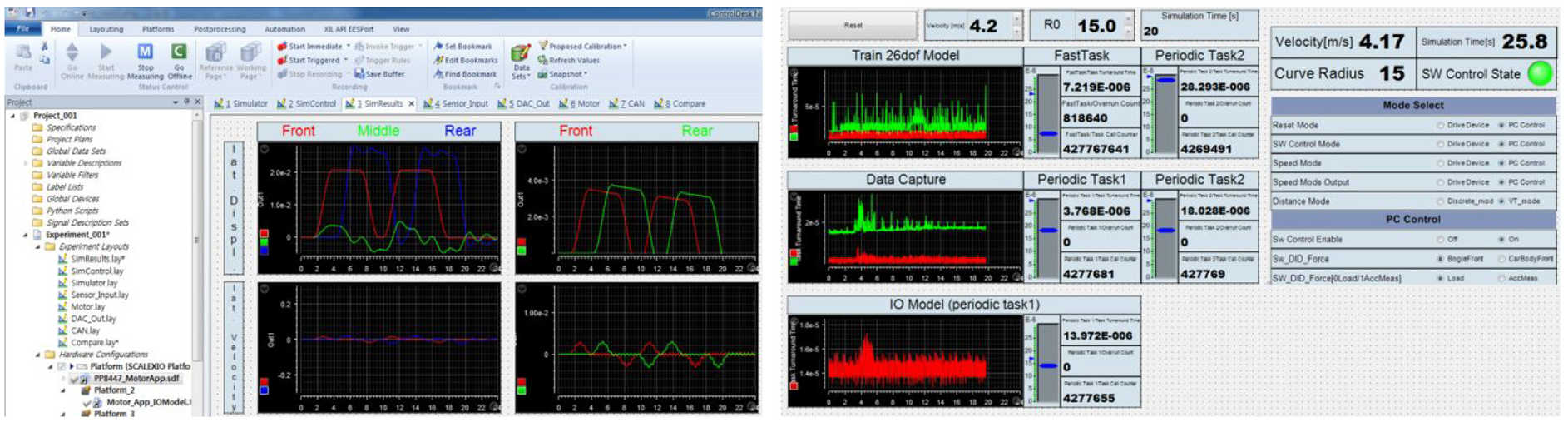
Status monitoring and control variable definition using the control desk.

Realization of dynamic characteristics of real-time analysis model using motion desk.
Controller design
Normal railway vehicle uses rigid wheelset, so the restoring force is automatically generated by applying the same traction torque to the left and right sides. However, the independently rotating wheelset can generate restoring force only when independent torque control of the left and right wheels is added in addition to the traction torque.
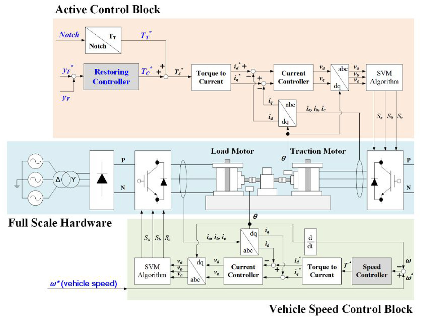
In this paper, the mechanism for generating IRWs (Independently Rotating Wheels) restoring force through individual motor torque control is described, and the lateral displacement and yaw angle-based restoring control strategies have been verified using HIL simulator.
The lateral displacement-based restoration control strategy is shown in Figure 11. When a left lateral offset occurs (YF*-YF) in the wheelset, the left wheel torque is increased (TC*) and at the same time, the right wheel torque is increased (TC*) in the opposite direction.
Active control concept diagram for load motor and traction motor constituting HIL simulator.
In this case, a yaw moment in the clockwise direction is generated due to the difference in the left and right wheel torque, thereby generating a restoring force that returns to the center of the rail. On the other hand, when a right lateral offset occurs, the yaw moment in the counterclockwise direction is generated by controlling the restoration torque of the left and right wheels. A similar control strategy can be applied to the yaw angle of the wheelset caused by the traction torque TT* that generates the propulsive force of the vehicle under test and the restoring torque TC* that generates the lateral recovery force.
The entire system consists of a remote-control device (Lever), a real vehicle controller and hardware, and RTDS (Real Time Digital Simulator). The remote-control device transmits the traction data (notch information) to the IRWs controller through CAN. In RTDS, the 26-degree-of-freedom dynamic equation of a three-module tram is calculated in real time. The traction torque and recovery torque are controlled by the IRWs controller using vehicle data (lateral displacement and yaw angle) calculated in RTDS. The transmitted notch information is converted from the traction controller to the traction torque (TT*), and the restoring controller feedbacks the lateral displacement of the vehicle and outputs the control torque (TC*). The IRWs traction motor is controlled with the final torque (TS*) combined with the traction torque and control torque. The propulsion torque (TT) and control torque (TC) information is transmitted to the RTDS to solve the IRWs vehicle equation in real time. At this time, the vehicle speed can be obtained by calculating the longitudinal equation in RTDS using the transferred traction force (TT). The calculated vehicle speed is input to the vehicle speed control block, which is a load motor controller, to simulate vehicle driving. The 26-degree-of-freedom dynamics equation is solved in real time using the transmitted control torque (TC), and the calculated result includes the lateral and yaw information of the vehicle. This variable is fed back to the vehicle controller to perform restoration control. The calculated state information of the vehicle is mapped to a 3D vehicle model using the real time animation function included in dSPACE’s Motion desk program, and implemented to visually check the movement of the actual vehicle.
HIL simulator analysis results
Evaluation of the performance of the restoring control algorithm was performed through real-time experiments under three driving conditions. In particular, it is possible to verify the performance of the development controller in advance before performing the actual driving test through real-time analysis of the same conditions as the test track that is going to proceed with the driving test of the actual test vehicle.
Analysis with impulse disturbance when running on a straight rail
First, as shown in Figure 12, the characteristics of the impulse disturbance in a straight section were analyzed. When impulse disturbance is applied in the lateral direction during straight running, displacement occurs in the lateral direction. When the lateral displacement is greatly increased, the wheel flange and the rail are in contact, so the lateral displacement is limited to a maximum of 6.5 mm. Figures 13 and 14 show the analysis results. The wheel diverges without restoring control to the center of the rail even if sufficient time has passed since the disturbance was applied. This shows that the IRWs does not have automatic recovery capability unlike the Rigid wheelset.
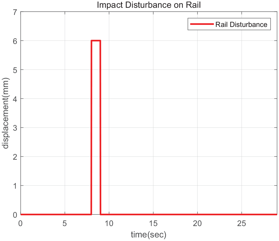
Analysis condition considering lateral disturbance on straight track.
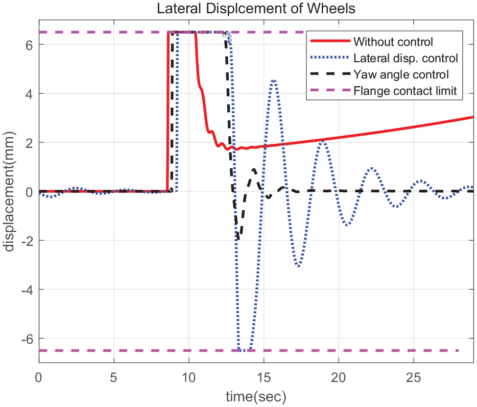
Lateral displacements with and without restoration controls of impulse disturbance analysis.
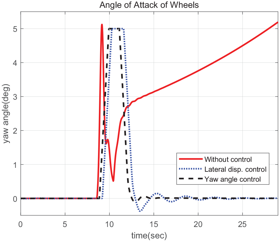
Yaw angles with and without restoration controls of impulse disturbance analysis.
The lateral displacement based restoration controller is additionally operated to generate a torque difference on the left and right wheels. Compared to the result in the figure without restoring control, it can be seen that the wheel is restored to the center after the impulse disturbance input. The lateral displacement based control is controlled with accompanying vibration, whereas the yaw angle based control has a faster recovery control performance and less tendency of vibration than the lateral displacement based control. Since the individual motor torque control is performed with the yaw moment using the torque difference of the left and right wheels, it was confirmed that the yaw angle based control has superior dynamic characteristics compared to the lateral displacement based restoring control.
Analysis with track irregularity when running on a straight rail
The actual rail has irregularities as shown in Figure 15.
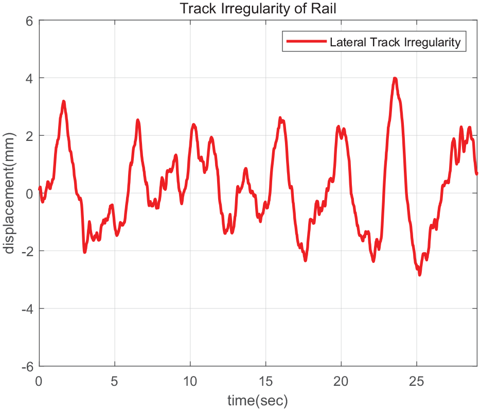
Lateral track irregularity of real test track.
The irregularity of the rail acts small size and high frequency disturbance. As it accumulates, the lateral displacement gradually increases. Therefore, a test was performed to verify the restoration control characteristics for the irregularity of the rail. The irregularity of the rail used in the analysis was measured values of the actual rail. This value was added to the lateral freedom model in the 26-degree-of-freedom vehicle model and configured to act as disturbance. Figures 16 and 17 show the result of performing the restoring controls.
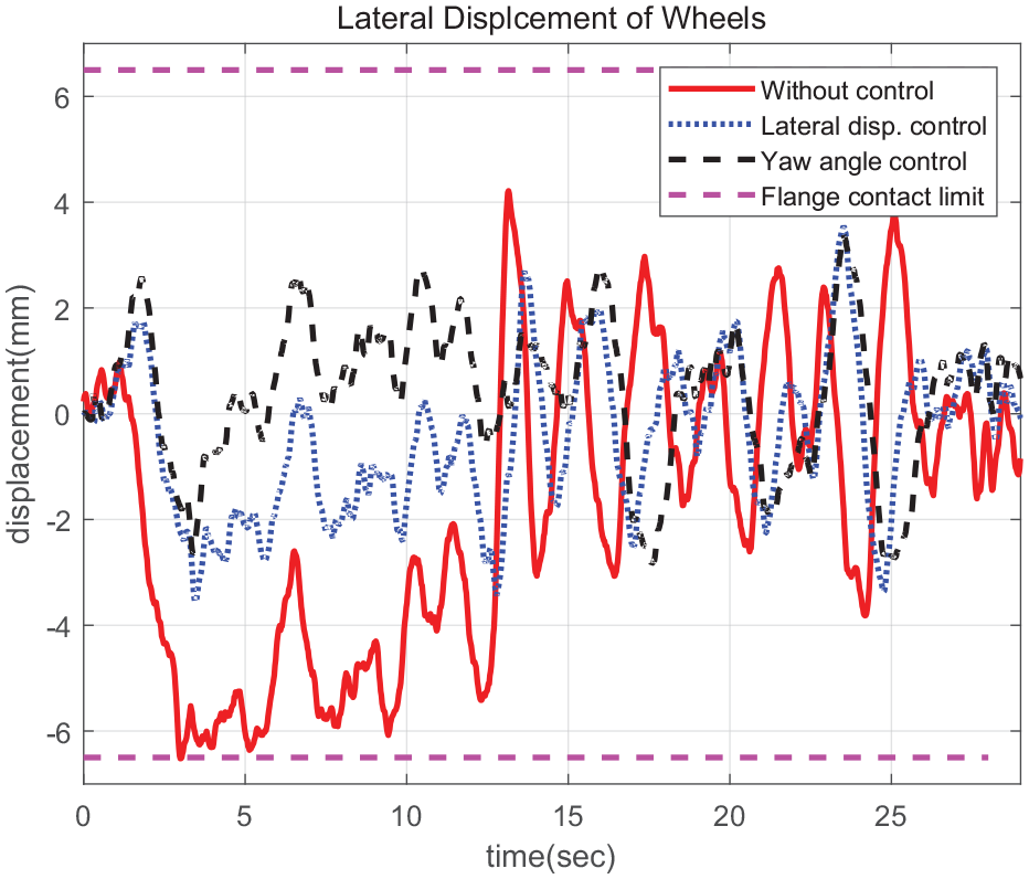
Lateral displacements with and without restoration control of track irregularity analysis.
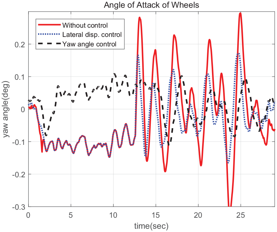
Yaw angles with and without restoration control of track irregularity analysis.
The lateral displacement gradually increases before performing the restoration control due to the irregularity of the rail, but the lateral displacement decreases after applying the restoration control. On the other hand, it can be seen that the yaw angle has little improvement effect due to restoring control. Similar to the impact analysis results, the yaw angle based restoration control shows superior control performance compared to the lateral displacement based restoration control. The lateral displacement is effectively controlled according to the change of the yaw angle. Since it was confirmed that the yaw angle based control is excellent through the restoration performance analysis of impact disturbance and the track irregularity, the analysis of the actual driving conditions was performed by applying only the yaw angle based restoration force control.
Analysis with real driving track including 15 m curve radius sections
A yaw angel based restoring control strategy is applied to improve driving performance when driving on a sharp curve. As shown in Figure 18, the track was secured have a mixture of a straight section and a sharp curve sections with radius 15 m. Figures 19 and 20 shows the results of running on the test track.
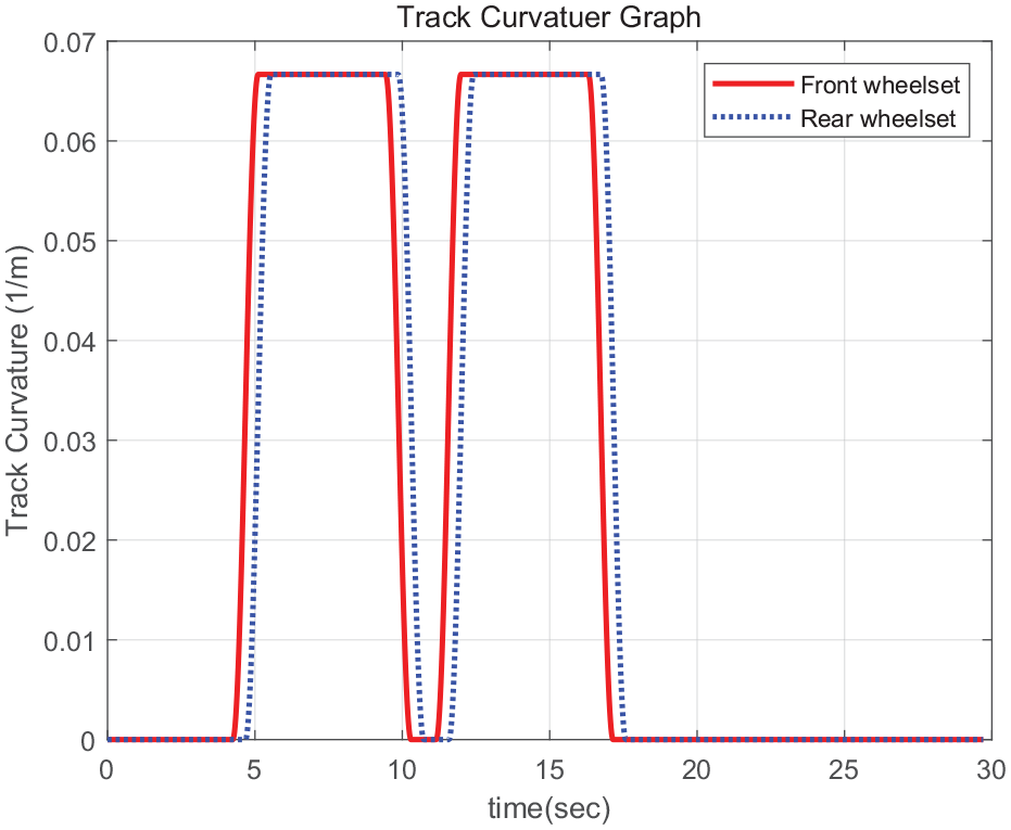
Track curvatures of test track including two 15 m curve radius sections.
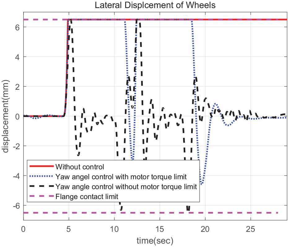
Lateral displacements without and with control considering motor torque limit.
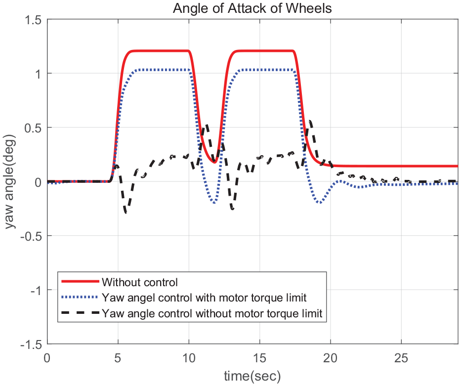
Yaw angles without and with control considering motor torque limit.
In the straight section, there is no extra disturbance, so it is operated in the center of the rail, and when entering the sharp curve section, lateral displacement is largely generated in the vehicle. It can be seen that the lateral displacement is large while passing through the two sharp curves and the lateral displacement is not restored even after passing the sharp curve sections.
Since the superiority of yaw angle control was confirmed through the two track condition tests above, only yaw angle control was verified in the test track condition including the two sharp curves. The results of applying the proposed restoring control strategy with and without considering motor torque saturation on sharp curve driving.
A very large restoration torque is required for restoring control on the sharp curve with a radius of 15 m, but the torque that can be output from the motor is limited. Since the required restoration torque is difficult to generate, sufficient restoration performance is not exhibited when driving on a curved line. In order to verify the validity of the proposed control strategy, the same test was performed without considering the saturation of the output torque of the motor. It was confirmed to secure sufficient control. It can be seen that the time between the contact of the flange and the wheel is greatly reduced and restored to the center of the rail. Therefore, it was confirmed that when the proposed restoring torque control was applied, there was room for a significant improvement in the driving stability on a sharp curve than when only the traction torque was controlled.
Conclusion
The proposed IRWs restoration control strategy has the advantage that it can be implemented only by changing the software without adding actuators and sensors. The verification of IRWs restoring control strategy using a real vehicle requires a great deal of manufacturing cost, so most of the verification was performed through analysis using a numerical model or through a scaled model and roller rig test. However, these methods have the disadvantage that there are little similarities with actual vehicles. In order to overcome this limitation, this study proposed the HIL simulator and test method to verify the effectiveness of the restoring control strategy to improve running performance of IRWs.
In the case of the actual vehicle driving test, it is possible to verify the lateral force through measurement using a strain gauge. In the case of scale roller-rig tests or HIL simulator, it is difficult to verify indices such as lateral force or wear, so the lateral displacement and yaw angle, which can be relatively checked for control performance, were selected and compared as the control performance index. In particular, the lateral displacement causes flange contact between the wheel and the rail in a disturbance or curved condition, so the limit of the flange contact displacement is clarified and the flange contact is reduced through control. Flange contact limit is displayed in the result graph so that the reduction trend of the contact frequency or contact time of the flange can be confirmed through the lateral displacement. It was confirmed that the proposed yaw angle based restoration control strategy secured better restoration performance than the lateral displacement based restoration control under impulse disturbance and rail irregularity conditions in straight driving and curved section running.
It is expected that the lateral restoration control will improve the sharp curve driving performance, reduce noise and vibration, and prevent serious accidents such as derailment. The process of verifying the individual motor torque control technology for improving the driving performance of the independently rotating wheel type railway vehicle using HIL simulator is summarized in Figure 21. A HIL simulator environment was built by connecting the PSMS motor performance test bench and the controller including the inverter with the virtual railway vehicle model.
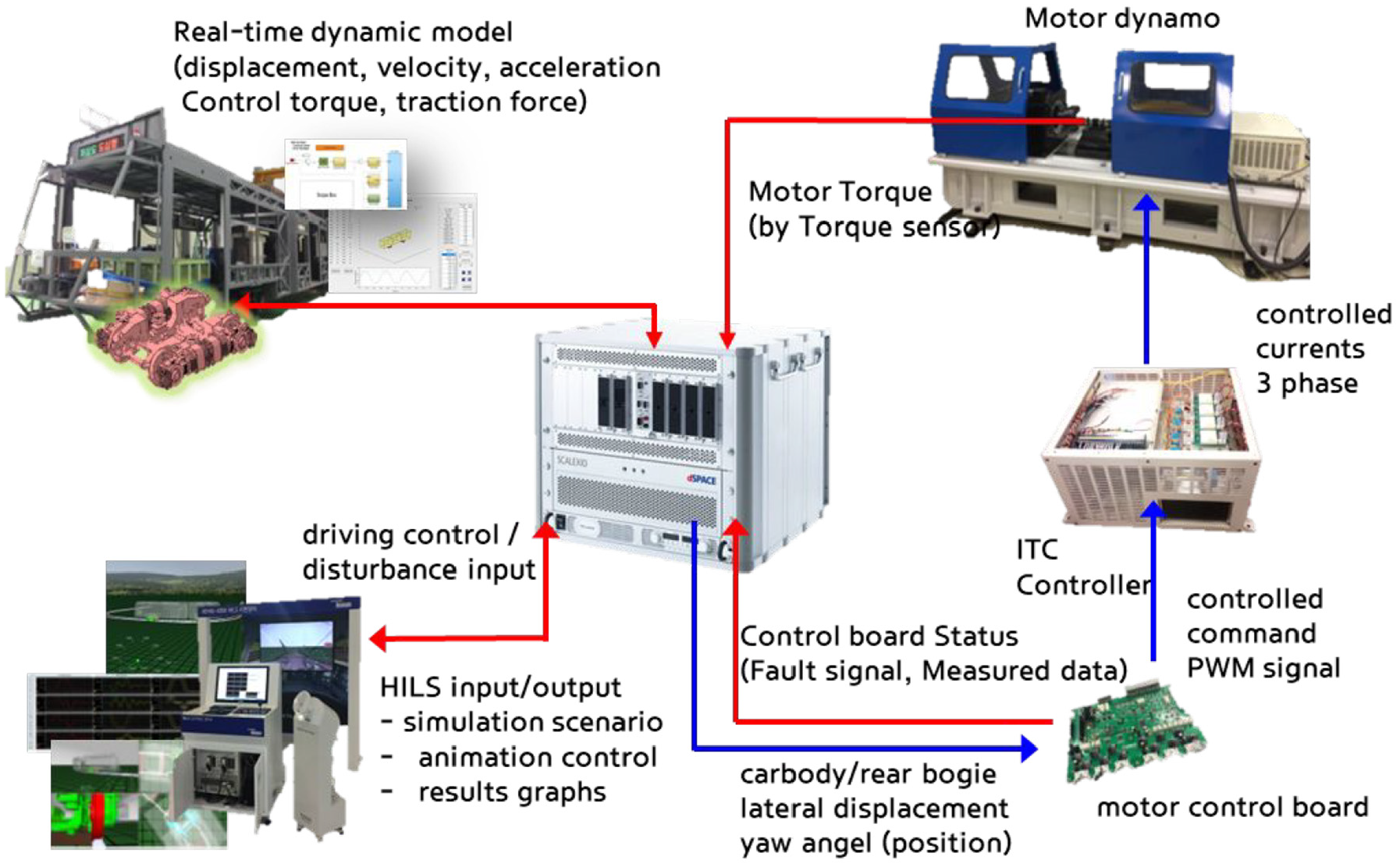
HILs configuration of individual motor torque control technology verification test.
The contents of control development using small-scale roller rig have already been published, and this paper deals with the contents of control performance comparison and verification using HIL simulator. In the future, content on actual vehicle driving analysis and tests will be announced.
For lateral displacement and yaw angle control, it is important to secure a sensor for measuring lateral displacement and yaw angle, and to solve the problem of measurement noise and failure, a position-based curve to enable robust control along with research on condition prediction technology including Kalman filter. A study is planned to apply feed forward control using radius and track information to actual vehicle driving tests.