
Abstract
To meet rising demands in performance and emissions compliance, companies are driven to develop systems of ever-increasing complexity. In-the-loop methods use a hybrid approach combining a physical subsystem with a virtual subsystem in real-time that can make product development processes faster and cheaper, enabling physical subsystems to be tested in real-world conditions while they are immersed in virtual environment simulation. These techniques evolved from being used solely in controller development with only the embedded controller placed as hardware-in-the-loop (HIL), to being a more holistic technique for system synthesis, capable of both component- and system-level studies. This paper delves into the development of the latter form, henceforth referred to as ‘component-in-the-loop’ or CIL. It provides a literature review of the growing uses of the technique in automotive development, giving a general implementation guidance in system architecture, methodology and control system structure. Furthermore, it suggests the need to clarify terminologies related to in-the-loop methods for a more efficient taxonomy. Definitions are proposed where deemed appropriate. In the age of search engines, this should facilitate knowledge transfer within and across disciplines. Finally, it highlights the key challenges in constructing such systems while discussing attempted solutions. CIL has reached a state of maturity where it is ready for wider adoption and continued technological progress will only push its potential further.
Keywords
Introduction
Competition, compliance and timely market introduction: these three factors keep manufacturers on their toes with regards to their product development processes. In order to facilitate this, model-based techniques such as hardware-in-the-loop (HIL), software-in-the-loop (SIL) and component-in-the-loop (CIL) are becoming more widely used. The progress of cyber-physical experimentation is signalled by the development of new terminologies, arising due to the need to distinguish them from their origin. This paper focuses on the use of component-in-the-loop (CIL or sometimes CoIL) techniques, which test the interaction between a physical component and a virtual component, within automotive applications.1–3
In-the-loop techniques, rapid prototyping, and cyber-physical systems in general are used for modelling purposes, to test the behaviour of specified (but not yet built) components, for validation and testing, and for investigating faults. 4 Similar techniques are used for distributed testing where different experimental facilities from geographically separated locations are combined into one experiment.
The purpose of this paper is to foster, document and recognise CIL as a powerful methodology with a great potential that remains to be unlocked. Advancements in key enabling technologies, simulation tools and modelling techniques are crucial for this to happen. An important motivation for the paper is facilitating the adoption of CIL by distilling common challenges both in the language used and the practical techniques deployed, giving recommendations based on literature where appropriate. The body of the paper is split into four main parts. Section 2 examines the current issues in terminology and proposes distinct definitions for a more efficient categorisation. Next, Section 3 suggests a general approach for implementation, comprising a reference architecture, methodology and emulator controller structure. Section 4 endeavours to illustrate the breadth of applications that CIL has in mobile machinery development. Finally, section 5 reviews the common practical challenges faced in the implementation of such systems while providing a survey of possible solutions that have been attempted or are currently being developed.
Taxonomy and terminologies
This section highlights the issues in in-the-loop- (IL-), HIL- and CIL-related terminologies and attempts to recommend universal definitions. As a minimum, it should make users aware of the various terms and synonyms that are used in this area. See Figure 1 for a plot showing how the use of terminology has changed over time. Table 1 contains a list of common abbreviations, and Table 2 a list of common symbols.
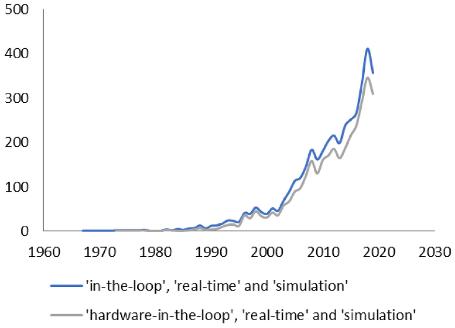
Plots of search terms showing the rise of IL and HIL publications over time, reflecting the relative rise in interest.
Abbreviations.

Symbols.

Real-time simulation
Bélanger et al. 5 describes real-time (RT) simulation (RTS) as model execution where internal variables and outputs are calculated within the same length of time as a comparable physical system. This can refer to complete virtual models but also encompasses hybrid systems, HIL and rapid controller prototyping (RCP). Both HIL and RCP execution needs to be slightly faster than the RT deadline to allow exchange of data to and from connected physical components via the model interface.
Real-time simulations are of course just one application of cyber-physical systems (CPSs), which are computation and communication intensive computer systems interacting with physical systems. 6
Differentiating between HIL, CHIL, CIL and RCP
Brayanov and Stoynova 7 lists the definitions and descriptions of HIL coming from different papers, which points to an underlying ambiguity in the use of the term ‘hardware’ It summarises the main aspects of HIL as follows: the combination of virtual and physical systems (or software and hardware); the immersion of the physical parts in a modelled version of its environment (including the rest of the system in which it resides); execution of the models in RT; replacement of the modelled components in the physical space by a set of actuators; and design of the actuator controllers to emulate the interactions of the virtual system at the hardware interface. A majority of papers also characterise HIL as having a closed-loop configuration.1,8–11 To highlight the difference between ‘HIL’ and ‘CIL’ a brief history of the development of HIL is presented.
Early HIL applications (Figure 2(a)) proved useful in the debugging of complex RT control code in realistic conditions and became essential to the timely delivery of control systems. Initially, the ‘hardware’ referred to computing hardware such as an Engine Control Unit (ECU), following the terminology of computer science. However, more recent usage of that term sometimes extends to all physical systems. Increasingly, further physical components are used (Figure 2(b)) both to avoid non-linearities in modelling and to reduce the complexity of the model.

A simplified illustration of the evolution of HIL showing the progression from (a) early HIL over (b) control with physical components and (c) the study of non-controller components to (d) full CIL with surrogate parts.
Dating from 2006, 1 presents a review recognising that this ‘in-the-loop’ concept has been extended to cover the testing of components in simulated environments – called component-in-the-loop (CIL). Rather than the controller, these added components themselves are the subject of study (Figure 2(c)). Other terms that are being used to describe this more holistic technique include ‘hybrid simulation’, ‘pseudo-real testing’ or ‘cyber-physical experiment’. In structural engineering it is more specifically referred to as ‘real-time hybrid simulation’ (RTHS). The counts for these terms from three different search tools are shown in Table 3.
Search log for the terms IL, HIL and its other aliases.

Data are up to the end of 2019.
Work on CIL applications has been presented where components are completely replaced by surrogates. 12 Unlike in previous generations of CIL methods, these techniques allowed realistic preliminary feasibility studies to be carried out without having the component present (Figure 2(d)). Sometimes, the term HIL is used widely without distinction for any in-the-loop technology, extending the term hardware from just the controller (the definition used in computer science) to any physical experiment. This has given rise to the variation ‘controller-HIL’ (CHIL) to stress that it is the physical controller that is under test.
This review generally follows the narrower, original definition of HIL, which is compatible with the term CHIL. In places where wider definitions are commonly used in the literature, this will be pointed out explicitly.
The CIL integration may have the controller either embedded in hardware or as part of the model. Some refer to this architecture as supporting ‘rapid control prototyping’ or RCP. RCP is a hybrid-testing technique where just the controller is kept virtual, usually running on high-throughput hardware. 13 Such hardware is often referred to as ‘real time’ (RT) in the sense that models may be run at a speed that matches actual physical behaviour. To avoid confusion, it is proposed that CIL systems with an embedded controller be referred to as CHIL-capable, while the rest may then be referred to as RCP-capable.
HIL methods classified based on interface level
The layers of a common mechatronics system are shown in Figure 3. Based on this, Bouscayrol 8 suggests that HIL versions of such systems be classified in three ways, according to their level of partitioning: signal-level, power-level and mechanical-level.

The layers of a common mechatronics system. 6
In ‘signal-level HIL’ only low-voltage and low-current signals are transferred between the virtual and physical environments. This covers all the traditional CHIL architectures. In ‘power-level HIL’ the load actuator exchanges power with the component placed in the loop and it may be using energy, generating energy, or both. This arrangement is commonly used in vehicle propulsion development for battery-in-the-loop (BIL) testing for electric vehicles (EVs) and hybrid electric vehicles (HEVs).
In ‘mechanical-level HIL’, the device under test is subjected to a load through a mechanical interface. Although the application of engine-in-the-loop (EIL) and transmission-in-the-loop (TIL) is becoming popular and falls in this category, the actual term is not widely used in mobile machinery industries yet. Note that although these terms are widely used, they do not fall under the narrow definition of HIL proposed here and are better classified as CIL or System-in-the-Loop.
Bouscayrol 8 presents a classification that is practically useful as it gives a clear picture of the type of interaction involved between the real and emulated system. Outside the power systems field where this originated, there are other types of HIL that do not fall simply in any of the three categories because their interface requires a different type of actuation. If studies in these areas become prevalent, new categories such as thermal-level and hydraulic-level HIL will naturally appear.
Defining methods based on the X-in-the-loop framework
There are several organisations who have recognised the advantages of various model-based design methods to the point of integrating them within their development process as a toolchain called ‘X-in-the-loop’ or XIL for short.14–17 To provide greater clarity of IL terminologies, definitions of methods falling under this toolchain are reviewed below.
Model-in-the-loop
Model-in-the-loop (MIL) was introduced in the 1970s in the form of the simulation of dynamic systems. The term ‘MIL’ was only recently put into general use and demonstrates that this early stage of system development is a critical part of the whole XIL process. It is only labelled MIL in the context of the XIL toolchain. Simply put, this is the standard modelling and simulation carried out in a computer. Several sources agree13,16,18,19 that MIL is characterised by having both the controller and the plant as models and having the simulations carried out at a variable time step. 15 adds that the plant and controller simulations are run in the same computer. There are many available software products built for this purpose. The models may also be created using more than one simulation package which are then linked and run together in a ‘co-simulation’.
Software-in-the-loop
One of the leaders in creating industry standards in modelling and simulation, MathWorks, describes capability to run software-in-the-loop (SIL) partially or in full. 20 Many developers use a partial arrangement where only the model of the device-of-interest (usually the controller) is written in a high-level language (C or C++ typically), compiled and executed. The rest of the plant is also compiled as code but interacts with the device-of-interest through function ‘blocks’, usually in S-function form.13,21–23 On the other hand, other publications24,25 present entire models which have been compiled and executed in a full SIL simulation.
The majority of literature devoted to this topic associates the term SIL for simulation carried out on a single computer – the ‘development computer’ or ‘host’.15,21,22 Where multiple computers are used, in a ‘host-target’ (terms defined in Section 3.1) set-up the process is termed instead as processor-in-the-loop or PIL.20,26 Some publications5,27 implicitly include PIL within an SIL architecture. This review will recommend s stricter use of the terms PIL and SIL to indicate two different development architectures.
Some say that in SIL, the models are executed in RT 11 while for others, this is not a necessary requirement,13,20,21,27 only that the models run at a fixed time-step.19,24
Processor-in-the-loop
Processor-in-the-loop (PIL) simulations are not general RT20,28 and can be carried out partially or in full. In full PIL simulation, the whole model is compiled, then cross-compiled into code which can run in a target processor where it is executed. In previous computing architectures, this meant a physically separate processor or target processor emulator was required.15,21,27 However, recent advances in virtualisation mean that this can now also be carried out on processors within the host-PC. 26 In partial PIL, only the parts-of-interest are cross-compiled and executed in the target. The rest of the plant is compiled and run in the host computer, communicating with the code in the target through function blocks. 20
In most of the XIL-related literature, PIL and SIL are conflated, or in some cases not acknowledged as significantly distinct. Bringmann and Kramer 21 argues that PIL is an important step as it ‘can reveal faults that are caused by the target compiler or by the processor architecture’. See Figure 4 for a graph showing the relationship between the different XIL approaches.

Overview of the X-in-the-loop framework and the CIL route.
Hardware-in-the-loop
Following the discussion above, HIL may be characterised as a system having a combination of virtual models and physical computing hardware in a closed-loop arrangement. All the models are compiled, cross-compiled and downloaded to a target processor for RT execution.
Component-in-the-loop
CIL is a variation of HIL where the system under test is a physical component such as an actuator, sensor, power conversion device etc. As discussed previously, CIL is typically the opposite of HIL, having any number of components from the original system placed in the loop, but never the embedded controller by itself. The difference in architecture is shown in Figure 5, and the typical arrangement of CIL in Figure 6. A transfer system consisting of a set of actuators and a controller connects the virtual and physical parts of a CIL system at the boundary. It works to give the physical parts as close to the same stimuli as they would experience as if there was no hybridisation.

Differentiating between HIL, CIL and RCP.

Basic constituents of a CIL set-up. The dotted lines are signals (usually electric) while the link between the transfer system and the physical component can vary depending on the actuator(s) involved (electric, mechanical, pneumatic, thermal etc.).
X-in-the-loop
Outside the XIL context, other fields may use different terms to refer to the same techniques. This is acceptable but becomes problematic when a clearly incorrect definition is borrowed and perpetuated in another discipline. For example, the use of the term ‘model-in-the-loop’ is found in Zhu et al. 29 and Plummer. 30 This demonstrates how important it is to clarify such terms; it facilitates work within and across different fields of engineering. The recommended definitions for XIL have been consolidated and listed in Table 4, and common definition for the application of HIL to powertrains have been collected in Table 5.
Recommendation of XIL definitions based on literature.

*Mutually exclusive options.
Any component from the reference system except the embedded controller on its own.
Recommended definitions for HIL-related terms.

Distributed exper iments
Although they are not usually considered within the context of component in the loop, distributed experiments share the architecture and many of the characteristics and challenges of CIL. The ‘virtual shaft’ is one example, where two systems are connected virtual as if they have a mechanical connection capable of power transfer. This concept was introduced in Payette, 31 and this paper already observes that the stiffness of the virtual shaft is critical for the stability of the system: the stiffer it is, the harder it becomes to achieve overall stability. This concept is now firmly embedded in powertrain testing.32,33
Distributed experiments in general are an active topic of research.34–37 One of the key challenges is of course the delay (and packet loss) caused by the network, which is a major topic of research in the field of networked control systems. 38
Other in-the-loop-related keywords
To make a clear distinction between the types of system being referred to through the course of the CIL development process, the authors suggest the following:
Reference system to refer to the original system in its physical form.
Reference system model to refer to the virtual model of the reference system.
CIL-integrated system model or CIL system model to refer to the modelled version of the intended CIL system.
CIL-integrated system or CIL system to refer to the reference system after part of it is converted in virtual form.
A term is needed for connectivity, but there is no clear term in current usage to describe it. NIL for network-in-the-loop is an option, but might be rather confusing. CCIL for connected CIL or CS-CIL for connected and shared CIL are further options.
Certain words, frequently used in the description of in-the-loop methods require clarification:
General implementation approaches
System architecture and methodology
The basic elements of a working CIL system are as follows (Figure 6):
A
A
The
A
A
The CIL process followed by developers will depend on the purpose of study. As shown in Figure 7, a general guideline is suggested based on the XIL approach and the methodologies surveyed in the literature. MIL is used to develop a reference model from which to validate the later SIL and CIL versions of the system. The protocol includes the use of both SIL and PIL. SIL for verifying the codes generated for the controller algorithm and the models of the intended virtual subsystem. PIL is more useful for troubleshooting integration-related issues. However, past users tend to choose from one of the two, most likely as a compromise between cost, time, and system requirements. MathWorks provides a guide for RT model preparation 40 which may be generally applicable across software platforms.
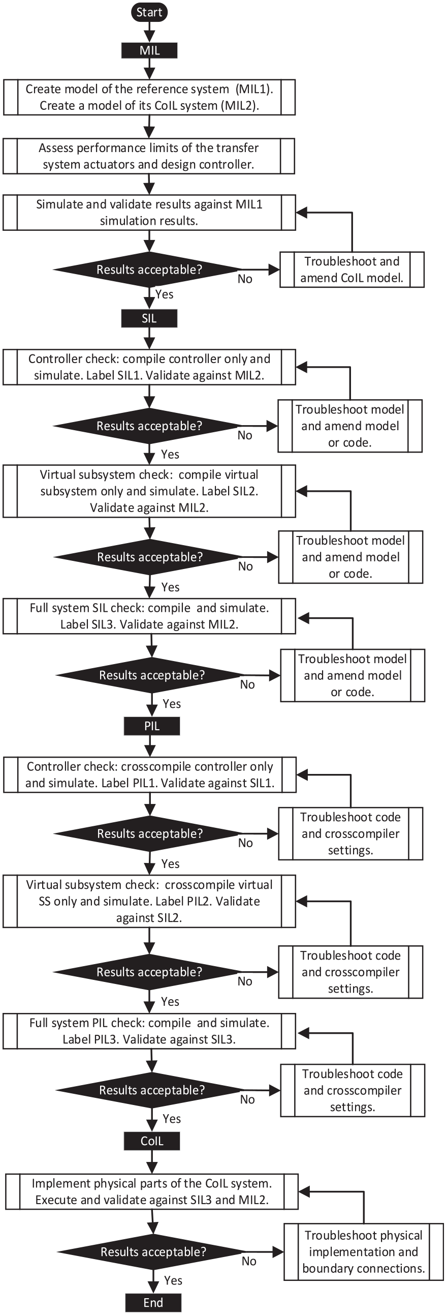
Suggested CIL process based on procedures found in literature.
Control system structure
Figure 8 shows a generic CIL system structure that combines the simplified representations introduced in Zhang and Alleyne 9 and Silva et al. 41 The words and phrases used in the description of the system are listed and defined below:

Simplified block diagram view of signal flows between the plant and transfer system sections of a CIL system:(a) Common configuration with indirect load actuator control (ILAC), (b) ILAC teased into constituent parts, (c) ILAC showingthe cascading input to output signal flows, and (d) Less common direct load actuator control configuration.
The CIL control structure has several inherent characteristics by virtue of its function as a hybrid emulator. First, it implies a causal forward-facing modelling configuration. A typical example is the use of a driver model to decide the demand setting for the system; in this case, a throttle position setting would cause the engine to act on the transmission, then the vehicle in a normal causal relationship. Although this is slower than its backward-modelling counterpart, the causal structure of the virtual subsystem facilitates later integration with physical components when transforming from a CIL system model to a CIL system implementation. Secondly, model reference control is an established form of the control design since where surrogate actuators need to be controlled to track the performance of a component that must conform with a defined set of static and dynamic characteristics.
These two characteristics result in a cascaded control structure (Figure 8(c)). The outer loop (red) takes measured variables from the physical subsystem (Ga and G
s, CoIL
) as well as the exogenous feed,
A breakdown of the cascaded structure reveals two types of actuators involved in emulating the load and environmental conditions around the CIL. Aside from the load actuators that come as surrogate components, there are intrinsic actuators which are part of the CIL itself. For example, Figure 9 shows a standard EIL with a dynamometer as the surrogate actuator and the common rail as the intrinsic actuator.

Simplified view of a typical EIL. EIL is an example of a single CIL (engine), double actuator (dynamometer and common rail) set-up.
An ‘indirect’ load actuator control structure was also distinguished in CIL systems in Zhang and Alleyne, 9 where the exogenous plant input is fed into the system via the plant (Figure 8(a)) rather than its transfer system (Figure 8(d)). With this premise, the authors suggested a general framework to design and analyse CIL control structures, giving guidelines of how to enhance controller performance within identified structural limitations.
Applications
Although the use of CIL in mobile machinery is relatively new, its uptake has accelerated according to the intensity of interest in alternative propulsion methods.
The complete picture of the development of HIL has been obscured due the military or commercial nature of early efforts which were never published. This lack of published work combined with the almost universal use of the term ‘HIL’ for CIL investigations underlines the importance of this review.
Engine
The transient response of an engine is difficult to model. Rapid load fluctuations can cause temporal variations in the air and fuel path, making exhaust emissions hard to predict. Having the engine realised gets around this challenge. An EIL is a standard engine-dynamometer setup with a feedforward model for computing the dynamometer commands.
Filipi et al. 46 describes an early EIL example (Figure 9). The arrangement is representative of a High-Mobility Multipurpose Wheeled Vehicle (HMMWV). It uses a 6.4 L diesel engine which connects to an asynchronous AC dynamometer. The models run on a target computer, communicating with the dynamometer controller at a rate of 250 Hz. Another system by Jiang et al. 47 emulates an automatic passenger car with a smaller 2.4 L gasoline EIL. The engine connects to a synchronous motor dynamometer with a permanent magnet rotor, with the models running at a rate of 1000 Hz.
Filipi et al. presents the use of their system for studying transient emissions of medium-duty trucks,46,48 HEVs and hydraulic hybrids.49–52. Teiner and Schneeweiss 53 uses their system to investigate the choice of control strategy influences, NOx emissions and fuel consumption in diesel parallel hybrid systems. Others also show that EIL can be used for the development and validation of power management strategies (PMSs) in HEVs.54,55 In-the-loop test methodology is also applied to engine components such as fuel injectors for direct injection engines 56 or for jet engines. 57 An engine simulation is used for HIL calibration in Riccio et al. 58
Battery
The battery fits the CIL approach particularly well because of its complex non-linear behaviour and sensitivity to a range of external parameters. Compared to mechanically integrated systems, the power-level interface allows much faster actuation. And because the interface is electrically simple, it is flexible with regard to changing components. It is no surprise that BIL currently forms a large part of CIL applications in vehicle propulsion.
The current survey shows that most BIL set-ups are used for emulating different types of HEVs and EVs. (Figure 10). They typically use a high voltage DC power supply to cycle the battery according to the driving schedule fed from the simulation. 2
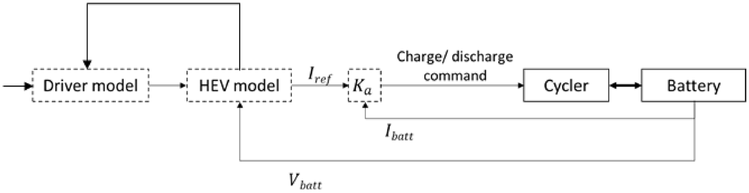
A typical BIL arrangement has a single CIL (battery) and single load actuator (cycler).
Argonne National Laboratory (ANL) is one of the key advocates of BIL and their system is well-documented in the literature. Several examples of its use include: investigation of battery performance59–61; evaluation of vehicle performance parameters such as fuel economy and range 62 and environmental impact studies. 63 Dagci et al. 64 describes another BIL system which will likely follow similar research trends at the US Environmental Protection Agency.
Other publications on BIL show its employment in battery degradation studies, 65 the comparison of consumption minimisation control strategies 66 and the investigation of planetary-gear-based HEVs. 67 Zhanning et al. 68 demonstrates a slightly different use for the study of fuel-cell-electric hybrid vehicles. Sarmiento-Carnevali et al. 69 shows the benefit of thermal conditioning with in-the-loop testing.
Fuel cell
Fuel cell IL (FCIL) testbeds can help support the rapid assessments of fuel cell (FC) technologies and control strategies prior to building full machine prototypes. Existing applications include Goyal et al., 70 where a proton-exchange membrane FC (PEMFC) with an output capacity of 1.2 kW was placed IL, in order to analyse performance of vehicles with either a standalone or with hybridised propulsion configuration. Its outputs were scaled up to equate the output of the 80 kW FC in the emulated vehicle before being fed to the virtual subsystem (Figure 12). A DC electric load draws power from the FC as if it was being drawn out by a real-life vehicle. Moore et al. 71 describes a similar arrangement (Figure 11) with greater attention on controlling the temperature and humidity around the cell.

An example of a set-up with a single CIL (FC) and four actuators (e-load, compressor and valves).

An example of a set-up with double CIL (engine and battery) and three actuators (dynamometer, cycler and common rail). 70
Motor
To avoid the need to model motors which are particularly difficult to parametrise, 72 motor IL (mIL) systems have emerged. The traction motor is one typically studied. Klein et al. 72 uses a typical motor-dynamometer test bench emulating a P2 HEV with a permanent magnet synchronous motor (PMSM). The system enabled acquisition of real motor thermal readings, from which a thermal derating strategy could be calibrated. The system in Awadallah et al. 73 was used to investigate how an off-the-shelf brushless DC motor installed as a traction motor on a mild HEV can assist to fill torque holes during gear changes in manual transmission. The authors discussed further work to expand its use into rapid control prototyping and validation. Fajri et al. 74 presents a two-pair mIL assembly to mimic a series HEV. The first pair has a DC motor acting as an engine emulator, mechanically linked with a PMSM which functions as a generator. The second has another DC motor which emulates the road loads, connected to a PMSM traction motor.
Drivetrain and transmission
By reducing energy losses in the transmission system, more torque is available at the wheels, improving fuel economy, and reducing emissions. Noise and vibration can also be reduced through transmission improvements. CIL is used in various ways for transmission and drivetrain development. Oh 75 for example, places an axial flux motor IL to study its potential as a wheel motor for different drivetrain configurations. In Steiber et al., 76 the developers use an induction motor (IM) to act as an engine emulator, physically connected to a transmission which is in turn attached to a high-bandwidth dynamometer. They intend to use the system for HEV development and prototype transmission design.
TIL can be useful in aiding fast and early testing of the transmission at relatively low risk. In Ahlawat et al.,77,78 the component of interest was a four-wheel drive automatic transmission, mechanically linked to three high bandwidth, low inertia, PMSM dynamometers.77,78 The first dynamometer imitates the torque input of the engine to the transmission, while the other two mimic the vehicle and road loads at the interface. The vehicle model has two separate wheel models, one for the left and one for the right wheels, to allow split-µ testing. The models also allow testing in both forward and reverse modes.
Powertrain
With increasing interest in electric and FC hybrids, there are numerous examples in literature describing a wide variety of powertrain configurations.
Lin et al. 79 describes a longitudinal dynamics emulator for a motorcycle, with an engine and transmission IL to carry out RCP tests of a fuel injection control algorithm. Awadallah et al. 80 shows a reduced version of a mild HEV emulator, this time with a PMSM emulating the engine, coupled to a dynamometer. An ultracapacitor is added IL to validate its function as an energy storage system.
Jin et al. 81 presents a testbed to facilitate the model-based design approach of different hybrid FC designs from modelling to prototyping. The authors place the whole powertrain IL including a DC/DC converter, lead-acid battery, supercapacitor and an induction-based traction motor. The IM interfaces with a 220 kW AC dynamometer. The PEMFC is kept within the model and a rule-based PMS is employed. Xie et al. 82 shows a very similar architecture, this time with a LiFeO4 battery pack, a brushless DC traction motor and a real PEMFC stack. An AC asynchronous dynamometer emulates vehicle and road loads. An observer-based approach to PHEV control is tested using HIL in Aubeck et al. 83
Some systems, typically developed for regulatory bodies or development and test organisations, are designed for both model flexibility and an ability to accommodate a wide range of architectures. One example is the HyVETS system at SwRI which has an engine, an AC IM on either side of a DC dynamometer, 84 and a bi-directional power supply which can be activated to mimic the battery. A conventional powertrain is emulated when only the engine is on, while a parallel HEV is emulated when all the parts are activated. To emulate a series HEV, the dynamometer is turned off and the engine and IM work as a generator while the propulsion motors work in the virtual space.
A highly flexible powertrain-in-the-loop (PTIL) called Modular Automotive Technology Testbed, described in Lohse-Busch 85 has the physical engine, clutch, transmission and wheels running on a chassis dynamometer, which emulates the road (see Figure 13). The system gives the choice of combining different modules depending on the vehicle being emulated (from conventional, FC to a range of electrified configurations). There is an option to use either gasoline or hydrogen engine modules, both of which are based on a 2.3 L engine. It also has a scalable energy storage module and a motor module which can mock different types of batteries with different capacities and traction motors. For electrified configurations, there is an open controller, allowing testing of any PMS. There is an option to use either an automatic or manual transmission module and the system can be driven virtually or by a human driver IL.

A single damper-in-the-loop representing the suspension in a quarter of a vehicle.
Jiang et al. 86 presents another PTIL, the available physical components of which include the engine, transmission, generator, traction motor, battery and a variety of power equipment. It also has two dynamometers, one for emulating loads, the other for emulating engines. It is possible to incorporate as many or as little of this hardware as needed. Within the power management unit, a DC/DC converter can be configured to play several functions including: charging and discharging the battery pack to a certain state of charge prior to a test run; emulating the battery or another traction motor/inverter pair; and acting as a battery cycler.
Hydraulics
CIL methods are also deployed in the investigation of hydraulic power systems. An excellent example that includes a detailed assessment of control methods is reported in Zhang and Alleyne. 9 The system consists of an AC motor acting as engine surrogate. The motor is mechanically connected to a variable displacement pump which is in the primary hydraulic loop along with three gear motors. Rather than the real equipment, with each gear motor, a gear pump was placed across a mechanical coupling, on a secondary hydraulic loop – the ‘load loop’. A pressure-relief valve along this loop is controlled by having it connected to a model of the loading subsystem being emulated. In this case, the total load comes from three subsystems, representing respectively the drive, the steering, and the machine implement. The valve regulates the pressure on the gear pump and in doing so, subjects the gear motor to a resistance comparable to that imposed by the real subsystem. The system is used for power optimisation studies in electro-hydraulic off-road machinery.
Suspension, steering and braking
The use of CIL has proved essential to control strategy development of semi-active suspension systems, in both electro-rheological87,88 and magneto-rheological dampers.89–91 The general system (Figure 14) consists of a single shock-absorber exercised as a quarter car emulator with the assumption that the same damping force characteristics are experienced in each of the remaining three corners of the vehicle. A damper-in-the-loop sits on a shaker table that is being stimulated by a servo-hydraulic valve. The valve position feedback (

Jin et al. 81 shows an example of load actuator emulating an unavailable component, in this case, a heater emulating a TEG.
Use of CIL to develop control strategies in steer-by-wire (SBW) systems are demonstrated in Refs.92–97 The typical approach uses a mechanical connection from the SBW system to a hydraulic cylinder which is controlled to emulate the lateral tyre forces generated when a vehicle is subject to steering manoeuvres.
For braking systems, CIL also plays a crucial role in the control design in antilock-braking systems 98 and pneumatic brake systems.99,100 An active decoupling suspension setup is testing using mechanical HIL in Liu et al. 101
Energy recovery
The literature reveals two examples of CIL applied to energy recovery from an engine exhaust gas flow. Both examples are concerned with the evaluation of thermoelectric generators (TEGs).
TEGs use temperature difference to create electricity through the Seebeck effect. Stobart et al. 3 demonstrates the CIL integration of a TEG in the context of heavy and medium duty engines. Recognising that using the post-turbine exhaust flow as the heat source may affect the gas catalysis process critical for aftertreatment, they explore the possibility of having a TEG in place of the EGR cooler. In this case, the CIL was simply the EGR cooler, controlled to perform as the TEG device by linking it with a TEG model and using model reference control to track the modelled behaviour.
By contrast, Vijayagopal et al. 102 places a surrogate heater to emulate a prototype TEG post-exhaust-manifold (Figure 14). This allows preliminary performance studies of the device to be carried out for estimation of fuel economy improvements.
Air systems
CIL is also deployed in the investigation of the control of air supply to propulsion system. One example is the implementation in Pischinger et al. 103 which places the air supply unit of a FC-powered vehicle IL in order to investigate air supply strategies during part-load operation. The unit comprises of a compressor with a water injector system (used for humidity control). A valve is used to emulate the backpressure that would develop in a real vehicle. As the driver model follows a drive cycle, the required FC output power, the traction motor speed, and torque are all calculated to provide new control set points for the powertrain control system. The compressor speed, injector valve position and load valve position, are calculated in a feed-forward sense.
The authors’ research team operates an engine testbed equipped with an electrically assisted turbocharger. The turbocharger is of variable turbine geometry and uses a switched reluctance motor on a common shaft with the compressor and turbine rotors. In a current project, a CIL architecture is under development to demonstrate a low-cost, compact altitude emulator suitable for realistic testing of heavy-duty engines. The overall aim of the project is to recreate the manifold pressures of a twin-turbo-integrated engine exposed to altitude conditions, using the e-turbo as the surrogate actuator (Figures 15 and 16). In these figures, the pressures P1 to P6 represent different stages in the system, and PA denotes ambient pressure. The dashed boxes represent conceptual system or component boundaries: the boundary of the system under test (the engine), the boundary of the actuator being used (the turbo-charger), and the boundary of the reference model (a different turbo-charger).
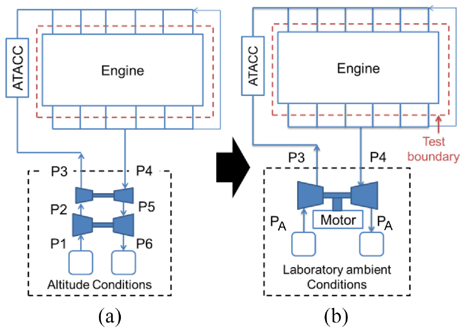
The goal of the emulator is to mimic manifold conditions of a twin-turbo engine at altitude: (a) reference system and (b) altitude emulator.

Overview of the planned CIL system architecture.
The electrical machine in the e-turbo can both motor for additional boosting or generate electricity from excess energy in the air system. Compared to existing altitude emulation platforms surveyed, the proposed emulator is novel in three ways: the movement of the engine test boundary to the manifolds; the use of an e-turbo; and the use of CIL to emulate the combined effects of a subsystem immersed in a virtual environment.
VeHIL
Vehicle hardware-in-the-loop (VeHIL or VIL) is increasingly used for the development of intelligent vehicle technology, including advanced driver assistance systems (ADASs) and connected and autonomous vehicles. It offers many advantages over the traditional in-vehicle testing methods. Not only is it carried out in a controllable laboratory environment where tests are repeatable, it also costs less and carries a lower safety risk. At first glance, VeHIL looks like a regular chassis dynamometer set-up, the difference being that models are connected to the chassis dynamometer, as well as other additional surrogate hardware, designed to immerse the vehicle in an artificial environment. Details vary according to the way in which the driving environment is represented.
One of the key advocates of VeHIL is TNO Automotive. Their test vehicle is fitted with various sensors which collect relative position data in the absolute traffic environment. 104 It is linked to dynamic models of other road users and the surrounding infrastructure. A moving robot represents a road user in the physical space, emulating their motion relative to the test vehicle. The relative position and motion of the fixed intelligent vehicle and the robot is taken as a representation of their absolute relationship within a real traffic scenario, making for a more space-efficient approach. The facility has been used for testing and validating various ADASs including longitudinal and lateral motion control, 105 pre-crash systems, 106 adaptive cruise control and forward collision warning systems. 104
The SERBER facility 107 uses multi-sensor road environment simulation software to create a virtual reality platform where the targets are projected on-screen. The arrangement removes the need for a fast-moving base, lowering risks, spatial requirements, and overall costs. Other VeHIL examples include Salaani et al. 108 where a real physical truck is used to validate simulation results for an automatic emergency braking system. Other example are presented in Refs.10,109–111 The use of Real Driving Emissions (RDE) testing makes emissions testing more complex, and VIL has been proposed as a way to replicate real-world conditions in a test rig. 112 Additional challenges exist for the testing of all-wheel drive vehicles. 113
Autonomy
Autonomous vehicles are constructed from sub-systems of great complexity, and physical testing is not sufficient to demonstrate appropriate system safety. It would require several billion miles of test driving to demonstrate safety comparable to a good human driver. 114 Therefore, more sophisticated methods are required, including in-the-loop testing.
CIL is a common development method for autonomous and semi-autonomous vehicles.115–119 Vehicle connectivity (V2X) creates additional challenges. 120
Common challenges in CIL
Creating a transparent integration
In any CIL system, ‘ideally, every component should be unable to distinguish between real, simulated or emulated components that it is connected to in the closed-loop configuration’. 11 Here lies the challenge of creating a transparent integration – or close enough – to ensure fidelity and avoid introducing instabilities. The factors that need to be addressed to achieve this are discussed below.
Creating models that are fast and accurate
A common challenge in the development of CIL platforms is the ability to create RT models that achieve sufficient fidelity when compared to the original system. Virtual investigations of automotive machines often entail complex multi-physics models that provide greater accuracy in simulation. CIL applications, however, cannot afford to incorporate such complexity if they are to meet their RT constraints. This process of creating models that balance both requirements of accuracy and speed is dubbed ‘proper modelling’. 121
A demonstration of proper modelling is presented in Filipi et al. 46 which use the Accuracy and Validation Algorithm for Simulation from Sendur et al. 122 where the Accuracy and Validation Algorithm for Simulation from Louca and Stein 123 is used to verify model fidelity. The fidelity check is followed with the application of the Model Order Reduction Algorithm 124 to simplify the model with the objective of a high degree of accuracy. The authors present a range of model reduction and deduction methods drawn from the literature.
To reduce the computational burden of their models, developers use various modelling methods. The approaches they use depend on the components that are ‘in the loop’ and the questions which they set out to answer prior to building their system.
For example, in a TIL arrangement where transmission behaviour is the focus, the engine may be reduced to a mean-torque-based lumped-parameter model as demonstrated by Ahlawat et al. 78 Greater detail could then be exerted in modelling and control of the input dynamometer, mimicking important behaviours such as engine torque pulsation and control mode changes. For HEV-emulating testbeds, the literature describes the use of the ‘dynamic average modelling’ method67,68 for simulating fast-switching power devices such as motors and converters. Mojlish et al. 125 presents various methods for RT simulation of electric machines, from simplified lumped-parameter models including phase-domain, direct–quadrature, and voltage-behind-reactance models, to more detailed physics models including finite-element and magnetic equivalent circuit methods. More generally, as part of their vehicle dynamics models, several developers choose to model their vehicle bodies as a point mass,46,47,77 accounting only for the longitudinal and heave directions while ignoring the pitch plane. 54 This is deemed sufficient for their needs to conduct efficiency and emissions studies on mild driving schedules.
It is also possible to meet the requirements of proper models using model inversion techniques. A significant enabler within this area is machine learning and deep learning where black-box models can be generated by training algorithms with only the input and output data of the process available. Thus, lengthy computations can be condensed into map-based artificial neural network (ANN) models where solutions can be obtained quickly. This is particularly useful for representing non-linear behaviours, and complex subsystems, especially when the details of their internal mechanisms are not available. Stobart et al. 3 uses a non-linear autoregressive exogenous ANN to predict the operation of a TEG. More specifically, they use a back-propagation ANN to model the non-linear part. As a result, their models can run five times faster than RT. Klein et al. 72 and Jiang et al. 86 utilises GT Suite to reduce their 1D detailed engine model into RT-capable mean value models (MVMs). MVMs in GT-Suite typically use an ANN-based engine model while the rest of the flow volumes are reduced by combining sub-volumes for faster calculation.
Although systems are becoming increasingly complex, this is countered by modelling techniques, supported by developments in artificial intelligence as well as advancements in computing technology. Today there are numerous manufacturers dedicated to producing target processors for RT execution. Software developers are also actively looking for ways to further facilitate proper modelling, as well as the entire XIL process. The continued progress in multi-rate sampling, hyperthreading, parallel computing, distributed computing and use of high-performance computer clusters, will increasingly enable modelling to a high degree of detail without sacrificing the ability to run in RT. Nevertheless, the more powerful elements of advanced computing will always need to be balanced with capital and running costs.
Designing the load emulator
Design of the transfer system also plays a significant role in achieving transparent integration. Its different aspects are discussed as follows.
Choosing actuators
Appropriate actuators need to be selected which can emulate behaviour within the acceptable range. Surrogate actuators cannot fully replace the reference system. They have performance limits and developers need to find those that best meet their operational requirements. For example, in the case where a single stage electric turbocharger is used to mimic a conventional twin turbocharger (Figure 16), an obvious limitation is expected from the use of a single-stage machine. The electric turbocharger’s degrees of freedom are different in scope because of the use of the motor as an ‘electrical degree of freedom’. Steady state experiments may be used to build a static map of the ‘emulation zone’ that will be supplemented by transient performance information.
The choice of an appropriate actuator for a given application is important, because too much difference from the reference behaviour can cause series control problems. The need for sufficient fast actuation was already discussed in Section 3.2. Schreiber et al. 126 describes four different levels of RT requirements: hard, firm, soft and near RT. The level required for each system depends on how fast the dynamics are at the interface of the load actuator and the CIL. Mechanically interfaced systems tend to have hard-RT requirements. Thus, testbeds requiring dynamometers as load actuators usually opt for ones with very low- or low-inertia due to their responsiveness. In TIL from Ahlawat et al., 78 the use of a fast-switching input motor was important to successfully emulate engine torque pulse. On the other hand, quasi-steady state, thermally interfaced systems may suffice with a near-RT response.
Choosing sensors
Fathy et al. 1 acknowledges that both actuators and sensors are key enablers for HIL simulation. However, although actuators are consistently discussed, sensor selection for optimising system performance has limited coverage in CIL literature. The role of sensors in CIL is to provide the vital physical data for the virtual models, although they can directly affect the quality of data collected. While sensor accuracy is always an issue, CIL can make very specific requirements in terms of fast response. A CIL-oriented study on sensor selection would make a valuable contribution in this area.
Choosing causality
Connection causality refers to the direction to which signals are flowing across a system. An actuator can be controlled in different ways depending on the variables chosen as inputs and outputs.
Dynamometers are the typical actuator in rotating mechanical systems. It can be controlled by commanding either torque or speed. Historically, in an engine-dynamometer arrangement, torque is explicitly controlled using the dynamometer and a torque control loop. Hrovat and Tobler 127 provides the justification for such direct torque control. Where a torque converter is included, it acts as a gyrator and this physical understanding needs to be explicitly accommodated in the formulation of the supporting models. Filipi et al. 46 notes the importance of a full understanding in characterising the behaviour of the torque converter.
Nevertheless, more than half of the relevant CIL literature choose the dynamometer to control speed.55,128,129 Even in the TIL set-up in Ahlawat et al. 78 the options are limited to controlling its input dynamometers through torque because the aim of the study to emulate engine torque pulse and wheel slip. Yet, they still use speed-control. This is perhaps best explained by Filipi et al. 46 which shows that in EIL tests involving torque control, instabilities in the engine torque signals persist despite tuning of the dynamometer control gains. They rationalise that such a strategy implicitly involves controlling acceleration – which is of a higher order than rotational speed. Higher order signals are noisier to measure and require higher actuator bandwidths for control. In this case, it reduces the bandwidth over which they can control the output torque of the engine. By adopting speed-control mode, they were able to alleviate their stability problem and the control loop bandwidth was improved to the desired range for their data acquisition system.
In another EIL study, 47 the authors choose to implement a torque control strategy despite acknowledging the causality difficulties reported in Filipi et al. 46 Nevertheless, they validate their EIL testbed successfully through a 10–15 mode driving cycle without reports of any issues. Steiber et al. 43 comments on the possibility of controlling the dynamometer through acceleration in addition to the two discussed options, but the author again chooses conventional torque control. There were no engine torque instabilities evident in their test results. Rather, their main challenge was in the disturbances that arose due to stiffer engine mounts and shaft than would have been found in the target vehicle. It is possible that for both cases, the systems had sufficient control bandwidth, allowing detrimental problems to be avoided.
It should be noted that speed control represents a compromise; in different applications where different surrogate actuators are used, changes to the phasing of speed and torque can lead to significantly different results.
For control of torque in diesel engines, the fuel path has a significant effect. Injector and cylinder dynamics all have a role to play. There is an absence from the literature of any form of cylinder pressure control that would make it easier to meet this control requirement.
With regards to actuators of electrical propulsion devices, FCs use DC loads to sink generated electricity while batteries use bidirectional DC power supplies. Most of the relevant literature2,64,67,71 adopts current-control mode where voltage is measured and used to generate the reference current command that will actuate the DC system to charge or discharge the CIL (as in Figure 10). However, most did not justify their choice. Zhanning et al. 68 only makes an allusion with the statement that its emulator control design should follow the causality of battery models, allowing smooth charge and discharge transitions. There is some guidance in literature explaining the advantages of current control, for example, simpler compensation requirements and higher gain bandwidth130,131 however they are not specific to CIL applications. Fuel cells and batteries are demand-led devices where current is drawn up to the point where the device is unable to meet the demand. Given their nature, use of a measured voltage to estimate a current – and then to impose that current matches the fundamental characteristics of the device.
To decide which causality is most suited for their work, it is useful for developers to conduct simulation and experimental studies prior to making a choice. To support future work, a summary of results from such studies would present an excellent contribution, illustrating the utility of different actuator choices and their relation to causality.
Control Strategies
While it may be sufficient to just connect the model to the actuator and sensor, this direct approach is not guaranteed to create a stable load emulator or experiment. Instead, a controller may be required for the actuator, and/or an observer for the sensor. Because the controller uses the model as a reference, this arrangement is called model referencing control or model reference control. 132 The fact that the reference is depending on the controller output makes the stability analysis of this system especially challenging (see Figure 17), similar to a cascaded control scheme but without the additional flexibility of the outer loop. A common extension is model reference adaptive control which goes back to very early empirical work. 133 The adaptive approach improves the control quality by learning and adapting to the behaviour of the system under test.

Block diagram overview of a RTHS arrangement.
Measured signals produced by sensors tend to be subject to noise which cause readings to deviate from their true value. Several tools have been developed to address this issue; in the automotive field, the authors of Hernandez 134 present a survey of optimal signal processing techniques. The typical approach is filtering, which unfortunately creates additional delays. Delays can also come from communication of these signals in addition to that caused by model computation. Usually, these sensor-based delays tend to be small compared to the time delay arising from actuator dynamics. 135 The stability does of course depend on the overall time delay of sensor, filter, processing and actuator.
The incorporation of compensators to address actuator-associated delays brings its own challenges as highlighted by Hu and Plummer 136 :
(1) implicit differentiation within the compensator introduces high frequency noise which makes the actuator signal saturate;
(2) the actuator may be difficult or impossible to compensate due to factors such as non-linear behaviours, pure time-delay and non-minimum phase behaviour which give an unstable inverse.
This highlights the typical trade-off in any control system between performance and robustness.
Few automotive CIL publications recognise the topic of delay as a significant concern to discuss it in detail, although there is extensive literature available in the control field. In Le Rhun, 137 describing a dynamometer-torque-controlled EIL development, the chief concern is the need to decouple shaft torque signals against test-bed vibrations, as well as the removal of delays, phase-lags and noise to ensure a high-quality engine torque signal is sent to the driveline model. To achieve this, they deployed a proprietary implementation of a Kalman filter.
The topic of compensators is rigorously discussed in other subject areas, such as the sub-structuring area of civil engineering as part of the RTHS literature. A typical RTHS experiment divides a large structure, for example, a three-storey steel reference frame, into physical and virtual parts, as in Lin et al.
138
shown in Figure 17. Servo-hydraulic actuators apply displacements (
When subjected to excitations, the actuator has a response delay equivalent to a negative damping. If the delay gets too large, the negative damping can get larger than the inherent structural damping. If it does, this will induce an unstable response that can be detrimental to the experiment. With this premise, Horiuchi et al. 140 uses a delay compensation method based on polynomial extrapolation to predict displacement. They later make improvements in their implementation using linear acceleration extrapolation, from which displacement can be derived. 141 A generalised approach is emulator-based control (EBC), as proposed for actuator-based HIL. 42 It can be used to explore the whole performance/robustness trade-off.
Numerous other publications in this field document the use of compensation methods based in control theory where the actuator is treated as a time delay system. This includes phase-lead compensators by Zhao et al., 142 derivative feedforward compensators proposed by Jung and Benson Shing 143 and Mercan 144 for minimising the influence of actuator lag, the Smith Predictor 145 and the virtual coupling method. 146 Chen et al. 147 investigates the use of an inverse compensation method which they later improve through a dual compensation scheme, 148 and further on to incorporate adaptive control law. 149 Out of these, the Smith predictor is often considered the standard approach for dealing with excessive time delays. A Smith predictor includes a model of the response, which in this context means a model of the system under test, which causes several issues. Requiring a model may defeat the purpose of the experiment, which is to find a model. In the case of large delays, the Smith predictor typically shows poor robustness to model errors.
Using an adaptive model can help to address robustness issues without sacrificing performance. The Neural NARX Smith predictor 150 is such an example, which uses an adaptive model to compensate for the time delay. Several authors151–153 report adding adaptive compensation methods to take account of the delay caused by inherent transfer system dynamics. More recently, compensation methods based on H-infinity optimisation has also been demonstrated by Hu and Plummer, 136 Ou et al., 154 Qian et al. 155 and Gao et al. 156 Moreover, there are also some papers that illustrate methods for analysing the compensator performance. Zhang and Alleyne 9 shows a general method for evaluating stability and performance of the transfer system control design based on frequency domain tools. Wallace et al. 151 presents a different technique for hybrid substructure testing using delay differential equation models. Chen and Ricles 157 improves on this by recognising the value of including an explicit integration algorithm in the stability analysis. In a further development of this work, 158 the authors propose the use of an equivalent discrete transfer function to do a frequency response analysis of the delay. Validation via experimental tests proved that their approach was highly effective.
Although automotive applications usually involve transient dynamics different to those seen in structural engineering, the underlying control problems are similar and thus the solutions are likely to be transferable. Attention to other spaces such as this one where rigorous research in CIL has already been carried out may prove to be highly beneficial.
Choosing where to partition
Partitioning a system into a real-world and a virtual part may appear straightforward. In the field of vehicle propulsion, for example an engine and transmission appear to have clearly defined boundaries. In other applications, boundaries can be much less clear: in the simulation of a load bearing structure for example the break between the virtual and the real-world can be made in a number of different ways.41,159 Even where there is apparent clarity on where the dividing line should be drawn, subtle distinctions are possible. Moving dynamics from the physical to the virtual world may render the control task substantially easier. 48
Typically partitioning follows these steps:
an initial partitioning based on the objectives of the programme (what is not easily modelled is included as a physical component while components that are not available are included in the numerical model);
compensating actuators for time delay and dynamics;
adjusting the boundary to balance stability and accuracy.
Optimisation can play a role. In a CIL experiment, a progressive change in the physical-virtual boundary may result in a changing prediction accuracy. Such accuracy gains often have a cost (such as increased measurement noise), so setting the scene for optimisation. 30
Reducing cost
Modelling most of the system and developing algorithms to ensure they run in RT to minimise computational requirements are two ways in which developers can control the cost of their CIL system. It is also possible: to use open-source software; to use cheaper off-the-shelf systems; and to re-use or re-purpose hardware. Further to these, there are popular techniques in the literature which make CIL integration more affordable and accessible by maximising use of available resources.
Distributing subsystems
Distribution can be carried out through the local or metropolitan area network (LAN/MAN), or the internet. LAN allows different equipment which are located in near proximity (e.g. the same building) to be connected to each other as if they were in the same room, for example in Petersheim and Brennan. 160 MAN allows connection of several LANs up to the size of a city. LAN/MAN connections tend to be connected via ethernet or Wi-Fi and are well understood, with its own set of IEEE standards 161 updated regularly since 1990.
The internet takes this further by linking various equipment located in vastly different geographical locations as a whole. This allows developers to access facilities which would have been too expensive or hard to obtain. It also facilitates collaboration and concurrent engineering.
Nevertheless, the internet has its own inherent challenges in the form of latency, jitter and loss. Latency measures how fast data packets are transferred to and from the sender and the receiver. This can be affected by the type of communication channel used, distance and the delay associated with processing and queueing data. Jitter is the variability of the network latency which can cause disorder in the data packets as they are received. Network loss means that not every packet sent reaches the destination, and the receiver needs to be able to recover from missing or delayed packets.
Ersal et al. recognise the potential value of internet-distribution (ID) in HIL, publishing most of the work in this area. In Ersal et al., 162 they reveal an advanced version of the HMMWV emulator in Filipi et al. 46 where the EIL’s virtual and physical parts are distributed in different towns via the internet. With the integration of a BIL set-up from a third location, it can also emulate a different machine altogether, namely, a hybrid-electric mine-resistant all-terrain vehicle. In Ersal et al., 163 they use the system to study the effects of coupling point choice on distortion of the signals sent over the network such that it can be made part of the design decision to optimise the fidelity of the system. They use it to investigate different methods for analysing the transparency of internet-distributed HIL systems including: statistical methods 164 ; approaches based on iterative learning control 165 ; and approaches based on Norm Optimal Iterative Learning Control. 166 In Schreiber et al., 126 an attempt is made to incorporate ID into the XIL methodology to check its feasibility as a tool for remote or shared experiments.
Using smaller hardware and scaling up
Scaling allows developers to reduce cost by allowing smaller and cheaper components to represent what would otherwise be cost-prohibitive full-scale equipment. There are also savings associated in the reduction of development time and the size of facilities required. Furthermore, it can amplify the advantages of network distribution by making it possible to connect a greater range of equipment. Nevertheless, users need to be careful in the method they use to scale in order to avoid errors into their simulations.
When scaling, some developers simply use scale factors in proportion to the capacity of the full device without taking into account the dependencies of physical quantities.67,167 Petersheim and Brennan 160 points out this oversight, demonstrating how dimensionless analysis, as defined by the Buckingham Pi Theorem, can be used for HEV components in CIL applications. To facilitate the process, they adopt a technique that uses matrix transforms as advocated by Szirtes. 168 Their case studies involve motors and batteries. Their results show that for better transparency a few requirements need to be met: dimensional matching of the input and output scaling; matching of the component characteristics; use of the same type of model for both the scaled and full-size component; and ensuring that the coefficients of the dimensionless system models for both the scaled and full-size components are equal for the dominant dynamics. Faithfull et al. 169 and Verma et al. 170 also use dimensional analysis for their CIL systems, this time, for creating a scaled-down version of a four-by-four vehicle and a HMMWV, respectively. Both groups show good similitude in their validation against MIL results.
For their BIL set-up, 171 illustrates another method based on per-unit scaling, as applied in electric power systems analysis. In this approach, the system quantities are expressed as fractions of a defined set of base values. Effectively, this makes per-unit system variables dimensionless, facilitating the extrapolation of results for the full-scale system. Again, such a method should be used with attention to effects which may not be accounted for in the downscaled test-rigs. For example, with regards to thermal effects in batteries, during operation, a battery pack can overheat while a single battery cell will not. 160
Perception
Value is derived in a CIL exercise from a reduction in the technical risk 172 associated with the design of an engineering system. CIL reduces risk by, for example, enabling an emerging design to be integrated ahead of the full physical assembly. But what makes the resulting prediction credible?
Examples from other research projects suggest an engineering support framework with tools that facilitate comparison and prediction. 41 An offline assessment using a MIL model provides an accurate foundation for assessment of the progress of CIL work. The use of a MIL model seems counter-intuitive, but a MIL model need only be accurate at a few test points to satisfy the requirements for validation.
At each stage of the CIL testing, an assessment may be made against the benchmark MIL results to check for acceptable accuracy. Optimum values of the parameters of the CIL test will ensure that accuracy is maximised subject to a stable and reliable set of experimental conditions.
The examination of extreme operating conditions and failure modes will help build a picture of complete system operation. In allowing the evaluation of failure modes, CIL avoids risky full-scale experiments and expensive system damage while building up a database of failure behaviour.
Conclusion
The variety of examples tackling every part of the mobile machine demonstrates how HIL has matured into CIL, a powerful product development tool that can do more than just controller development.
As the value of CIL in providing realistic testing and cutting down prototyping effort and costs is increasingly recognised, its practice is bound to increase. A general implementation guideline was laid out for interested users.
In the current age of search engines, a standardised taxonomy becomes ever more necessary to facilitate knowledge transfer across disciplines and information management for future users. A table of definitions was proposed. Definitions were also recommended as a starting point.
Furthermore, the review showed the existing range of solutions that are used to overcome key challenges in the RT integration at the physical-virtual interface, as well as in the practical matter of cost. The continued advancements in processors, sensors, actuators, local and internet distribution, parallel computing, control design, proper modelling and artificial intelligence will only contribute to the feasibility, fidelity, and affordability of CIL systems. With this trajectory, in future the possibility is open for highly complex system models to be integrated in RT without having to compromise accuracy. At this point, only the imagination and creativity will limit the innovation of CIL solutions.
Although this review focussed on applications in automotive vehicle propulsion machinery, the guiding principles that have found success in other engineering fields can be utilised elsewhere. New techniques offer the scope for substantial improvement in the performance of CIL development methods.
As publications across the whole of HIL continue to proliferate, it will be greatly beneficial for standards to emerge that encourage a common language across the discipline areas. It is the authors’ hope that this paper will assist that process.
Footnotes
Handling Editor: Chenhui Liang
Declaration of conflicting interests
The author(s) declared no potential conflicts of interest with respect to the research, authorship, and/or publication of this article.
Funding
The author(s) disclosed receipt of the following financial support for the research, authorship, and/or publication of this article: This work was supported by the UK Engineering and Physical Sciences Research Council (EPSRC) EP/L016362/1 for the EPSRC Centre for Doctoral Training in Carbon Capture and Storage and Cleaner Fossil Energy, led by Nottingham University. For the purpose of open access, the authors have applied a Creative Commons Attribution (CC BY) licence to any Accepted Manuscript version arising.