
Abstract
A new methodology is proposed in this study for active steering of a tram with independently rotating wheels (IRWs). This methodology has been developed specifically to improve the tram’s steering capability and to reduce wheel-rail wear. The tram is represented by a complex dynamic model with a diverse range of operating conditions, and traditional active steering methods cannot ensure that the tram can remain well-controlled throughout the entire range of operating conditions. The linear parameter-varying (LPV)-
Introduction
As a type of lightweight rail vehicle, the tram is widely used around the world. A tram has no stairs or steps between its entrances and its passenger cabin, which means that the low-floor design of the tram is very important because it can improve accessibility to the tram for the public. By using independently rotating wheels (IRWs), a tram can realize the required low-floor design, which will make it easier for passengers to board and alight from the tram, and will also improve both operational and organizational efficiency. However, the use of IRWs causes the tram to lose its self-steering ability, which results in the occurrence of serious wear between the wheels and rails, thus reducing ride comfort and increasing vehicle operation and maintenance costs. Therefore, it is highly important to solve the problems described above by using active steering control to enable the trams to regain their steering abilities. According to the different bogie structures involved, the available active guidance schemes for trams can be subdivided into actuated independently rotating wheel (AIRW), 1 directly-steered wheel-pair (DSW), 2 and driven independently rotating wheel (DIRW) types, 3 among others. In this work, the DIRW bogie scheme, which represents the most mature steering structure, is selected because the motor drives the wheels directly, thus allowing the trams to obtain their steering ability by controlling the motor’s driving torque.
Perez et al. found that active steering of a tram could be achieved by controlling the rotational speeds of its left and right wheels, and this rotational speed difference was proportional to the track curvature.4, 5 However, when a tram runs on a straight track, there is then no speed difference between the left and right wheels according to this algorithm, and the good steering performance required cannot be achieved. An integrated traction and steering controller for trams based on the P algorithm has been proposed,6, 7 where the driving torque that acts on the wheels was determined based on the speed differences between the right and left wheels. For running on curved tracks, an additional steering torque was provided based on the track radius. However, proportional control cannot eliminate static errors and it does not respond well to track irregularities. Gretzschel and Bose 3 and Lu et al. 8 proposed the use of a proportional-integral-derivative (PID) steering controller, which used the wheel lateral displacement and yaw angle as its input signals to realize steering and stability control and reduce wheel-rail wear. Kurzeck and Valente 9 of the German Aerospace Center studied the proportional-derivative (PD) steering algorithm for the tram. In their work, the maximum control torque was limited to protect the driving motor, and the effectiveness of the algorithm was verified through simulations and scale model tests.
The classical PID control algorithm cannot allow trams to achieve the desired steering performance because a tram is a complex multi-body system with a high number of degrees of freedom and strong nonlinear elements; for example, large numbers of nonlinear and varying parameters are involved in calculation of the creep force acting in the wheel-rail contact, and the track spectrum will cause high-frequency disturbances in the wheel-rail force. With the development of modern control theory, many researchers have turned their attention to modern control algorithms. The quadratic optimal steering control algorithm has been studied for trams to improve the steering control performance. Mei and Goodall
10
and Yang et al.11–13 studied the application of robust control theory to tram steering control and used uncertain parameters to represent nonlinear factors in the vehicle dynamics model to bring the steering algorithm one step closer to practical application. However, there was a contradiction between the robustness and the performance of their guidance control algorithm. Because of the complex operating conditions of a typical tram, it is impossible to rely on a single guidance controller to obtain the optimal control performance required for the vehicle throughout the entire running process. Therefore, it is highly important to study the use of robust linear parameter-varying (LPV)–
Tram dynamic model
The structure of the tram is shown in Figure 1. The components in order from top to bottom are: the car body, the secondary suspension, the bogie, the primary suspension, the IRWs, and the drive motor. The secondary suspension is mainly composed of air springs and traction rods, and the primary suspension mainly comprises rubber piles (arranged below the car body; not shown in the figure). The vehicle has two axles at the front and rear, and each axle has two IRWs with a drive motor on each wheel. By controlling the torque on these drive motors, the rotational speeds of the wheels can be varied to achieve steering control.

Structure of the tram.
The tram’s dynamic model, which is a complex nonlinear system, is characterized by its multiple degrees of freedom. Because this paper is mainly focused on steering control, only the lateral dynamic model is considered here. An illustration of the tram lateral dynamic model is shown in Figure 2.

Tram lateral dynamic model.
The LPV–


where Fy is the external lateral force, Tψ is the external yaw torque, and Tϕ and


LPV–H∞ control
State space model
The LPV-H∞ theory is a gain-scheduling-type control theory, and its main advantage is that the control parameters can be varied according to changes in the system parameters. 14 When compared with the time-invariant controller, a gain-scheduling controller overcomes the shortcoming that when the system parameters vary greatly, a fixed controller cannot achieve high performance over the entire operating range. 15
The standard LPV-H∞ control architecture is shown in Figure 3, where

Standard LPV control architecture.
The external lateral force Fy, the yaw torque Tψ of the IRW, and the running speed v are selected as the measurement variables because Fy and Tψ are related directly to the wheel’s lateral and yaw motions, respectively, and the speed v is strongly related to the creep force between the wheel and the rail. Furthermore, Fy and Tψ can be measured using an acceleration sensor and a gyroscope, respectively, and the tram’s speed v is easily acquired. We define θ1=v, θ2=Fy, and θ3=Tψ as the measurement variables, and thus

Tram with LPV-H∞ steering controller.
The LPV model of the tram can be expressed as follows:

where:


where
LPV model
The upper and lower bounds of each parameter of
For each parameter θi that varies within the interval [θli, θui], where i = 1, 2, 3, the parameter vector
where

LPV controller with performance adaptation
In addition to maintaining stable running of the tram system, the steering controller should also meet specific performance requirements. These requirements are: (1) the lateral displacement of the IRW should be limited to a specific range, which also serves as an important index for evaluation of the steering ability; and (2) the output torque of the motor should be within a nominal range to prevent damage to the motor. Clearly, the ∞ norm of the corresponding transfer function matrix should be minimized, and this can be achieved by adding weighting functions to the system.

Augmented architecture with weighting functions.
Here:


The magnitude responses of

Magnitude responses of
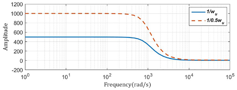
Magnitude responses of
According to Figure 5, the open-loop transfer function

By expressing the weight functions

the open-loop transfer function

where

Here,
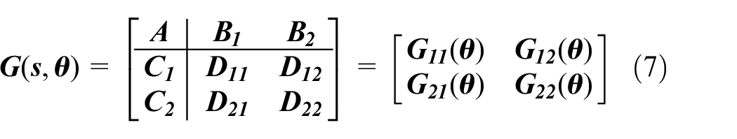
Controller Solving
The output feedback controller
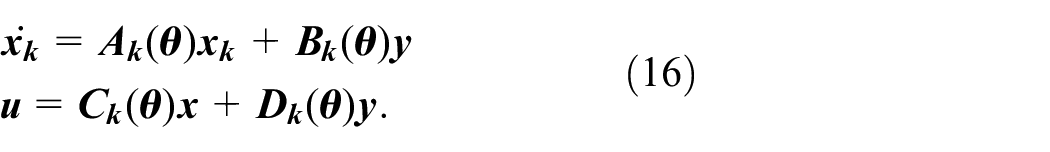
The controller order k is defined as the size of the matrix
where:
and:

The necessary and sufficient conditions for
D22(θ)=0; B2(θ), C2(θ), D12(θ), and D21(θ) are parameter-independent; the pairs (A(θ), B2) and (A(θ), C2) are quadratically stabilizable and quadratically detectable over
Given some positive scalar γ, the following statements are equivalent:
(i) There exists a kth-order LPV controller that can solve the quadratic
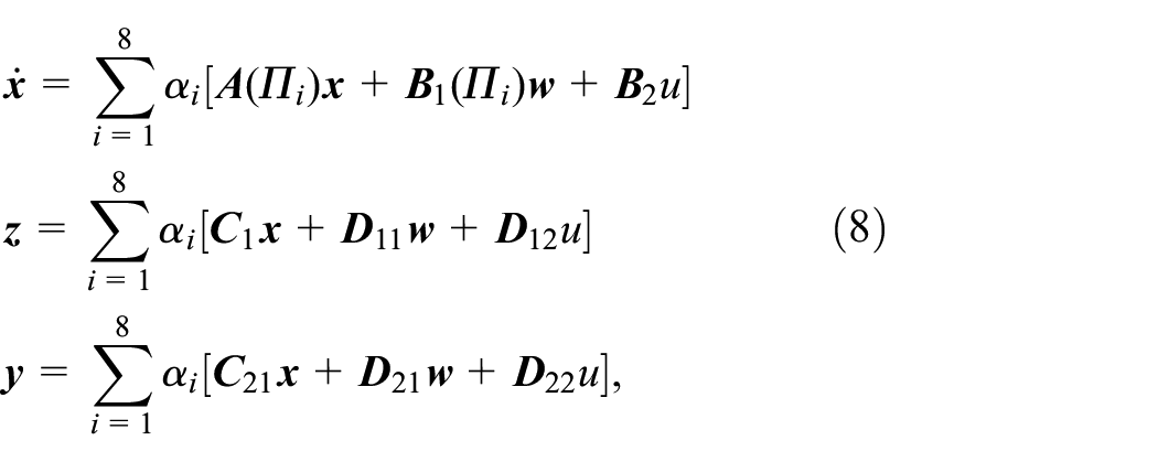
there exist an

where np=23=8, and
if and only if there exist two symmetric matrices (


The controller has a polytopic structure, which is described as:

Simulation results
The effectiveness of the active steering controller was verified by performing co-simulations: the steering controller and the vehicle dynamics model were established in MATLAB (MathWorks) and Simpack multibody system simulation (Dassault Systemes) software, respectively. The vehicle dynamics parameters are shown in the Appendix in Table 2. The standard UIC60 rail head and standard S1002 tread are used to simulate the wheel-rail contact, where the wheel-rail contact force is calculated using the FASTSIM method.
Four typical tracks and tram speeds, as shown in Table 1, were selected for the simulations to verify the steering performance. The speed v was set to 10 m/s and 20 m/s when the tram was running on a straight track, and was set to 3.2 m/s and 8.3 m/s, corresponding to curve radii of 25 m and 70 m, respectively, for running on a curved track.
Parameters for simulation conditions.

Because of the different performance requirements of the controller during running on a curve and a straight line, the values of
Simulation results for straight tracks
Case 1
When the tram is running on a straight track, the range for v is set to [10 20], i.e.,
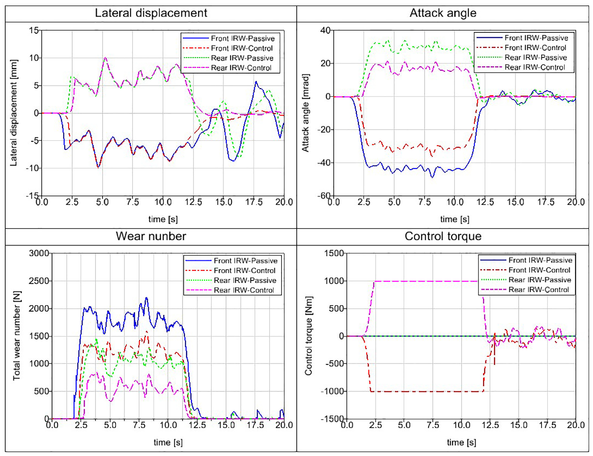
The simulation results for track 1 are shown in Figure 8. For the front IRW, the IRW’s lateral displacement reaches 9 mm in the passive case, suggesting that the flange has collided with the track; this should be avoided because it will cause serious wear between the wheel and the rail. When compared with the passive case, adoption of active steering control reduces the maximum lateral displacement to 0.55 mm and also reduces the average absolute value (ABV) of the lateral displacement from 2.87 mm to 0.18 mm.
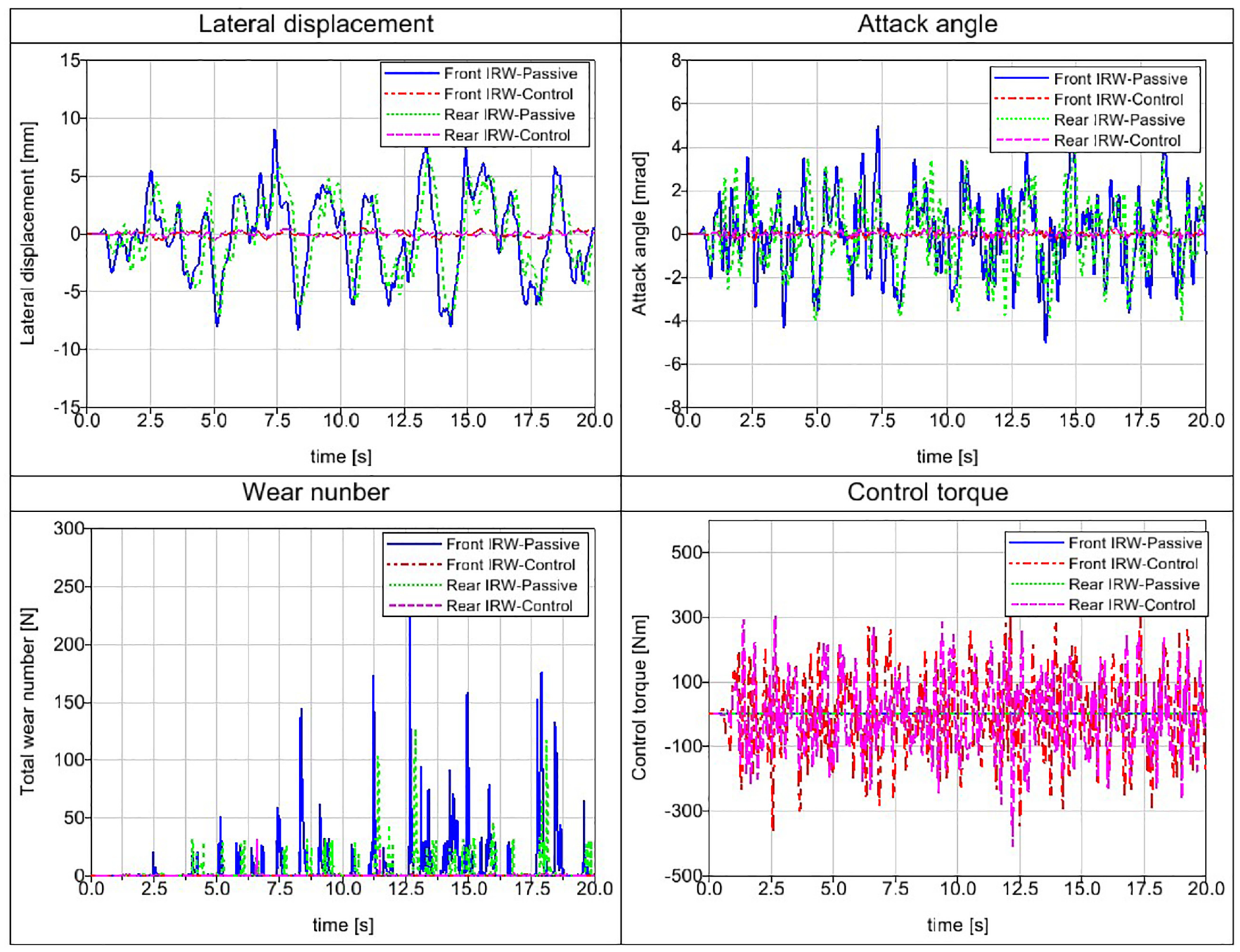
Simulation results for track 1(straight track, v=10 m/s).
At the same time, there is also a significant reduction in the IRW’s attack angle because the attack angle and the lateral displacement are coupled with each other. In other words, the maximum value of the attack angle decreases from 5.06 mrad to 0.32 mrad and the ABV value of the attack angle is reduced from 1.44 mrad to 0.09 mrad. The analysis for the rear IRW, which is similar to that for the front IWR, is shown in Figure 8.
The fundamental purpose of the steering control proposed in this study is to minimize the wheel-rail wear. On application of active steering control, we find that the average wear number of the front IRW decreases from 7.7 N to 0.4 N and the rear IRW’s average wear number decreases from 3.5 N to 0.5 N, indicating that a 91% wear reduction can be realized under steering control conditions other than the passive case. Within the constraint of the control output
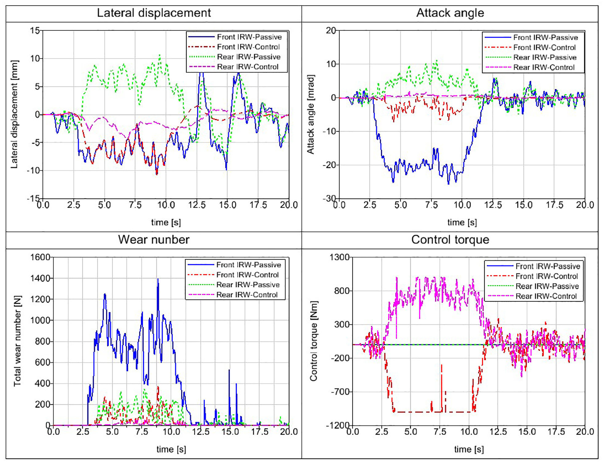
Case 2
The simulation results for track 2 are shown in Figure 9. These results reveal that the maximal lateral displacement is 9.25 mm when the tramcar is running at a speed of 20 m/s in a straight line. Nevertheless, the controller successfully maintained the IRW’s lateral displacement to within 1.17 mm. Additionally, significant reductions in the maximum attack angles of the front and rear IRWs from 5.84 mrad to 0.38 mrad and from 5.30 mrad to 0.35 mrad, respectively, were achieved. Moreover, the average wear number values for the front and rear IRWs decreased from 8.9 N to 1.2 N and from 4.1 N to 1.3 N, respectively, indicating that the active control method achieves a significant 82% reduction in the wheel-rail wear when compared with the passive case.

Simulation results for track 2 (straight track, v=20 m/s).
There is a limit for the maximum controller torque of 500 Nm to prevent damage to the motor. The simulation analysis reveals that the control torque only exceeds 500 Nm infrequently, with the torque remaining within 500 Nm for most of the time, demonstrating that the lateral displacements of the IRWs and the control torque meet the performance requirements for robust control.
Simulation results for curved tracks
Case 3
When the tram is running on a curved track, the range of
Simulation results for track 3 (curved track, v=3.2 m/s).
Nevertheless, the steering controller can reduce the attack angle on the curved track and cause the tram to return rapidly to the track center after the tram passes through the curve. The active controller could also reduce the absolute attack angles of the front and rear IRWs on the curved track from 44.1 mrad to 31.2 mrad and from 29.8 mrad to 16.8 mrad, respectively. Furthermore, the average wear numbers of the front and rear IRWs on the curved track were reduced from 1792 N to 1232 N and from 1043 N to 569 N, respectively. In summary, a 33% total wear reduction is achieved by using the active controller when compared with the passive case.
Case 4
In case 4, although no reduction in the maximum lateral displacement value is realized, the simulation data shown in Figure 11 reveal that the absolute attack angle of the front IRW was reduced from 20.9 mrad to 2.9 mrad by using the active controller. However, there are significant reductions in the average lateral displacement and the attack angle of the rear IRW, from 6.73 mm to 1.96 mm and from 5.6 mrad to 0.7 mrad, respectively, indicating that a practically ideal performance was achieved for the rear IRW when going along the curved track. Consequently, the active steering controller can reduce the average wear numbers of the front and rear IRWs from 819 N to 102 N and from 138 N to 12 N, respectively, resulting in a combined wear reduction of 88% when compared with the passive case.
Simulation results for track 4 (curved track, v=8.3 m/s).
Evidently, the simulation results realized in case 4 are better than those in case 3 under the same conditions for the maximum control torque. This indicates that as the radius of the curve increases, it becomes easier for the tram to pass through the curve. In other words, flange contact can be avoided and the wheel-rail wear can be reduced markedly by increasing the curve radius.
Conclusions
Trams use IRWs to achieve their low-floor structures, which are convenient for practical use, but also can cause severe wheel and rail wear during operation.
In this research, an active steering control strategy based on the LPV-
The controller design makes full use of the measured variables concept in LPV theory: by considering the primary suspension force and the wheel-rail force to be external measured variables, decoupling of the independent wheels and the tram model is achieved. This not only simplifies the controller design, but also improves the control performance.
The effectiveness of the active steering controller is verified through co-simulations: the steering controller and vehicle dynamics models are established in MATLAB and Simpack software, respectively, and four typical tracks and tram speeds are selected for the simulations. The simulation results show that the steering controller can allow the tram to regain its steering ability: the lateral displacements and the yaw angles of the wheels decrease, and the wheel-rail wear is reduced significantly. The simulation results demonstrate the feasibility and the effectiveness of the steering controller, which is highly meaningful when the large number of trams in service is considered.
Footnotes
Appendix
Parameters and symbols of the tram.
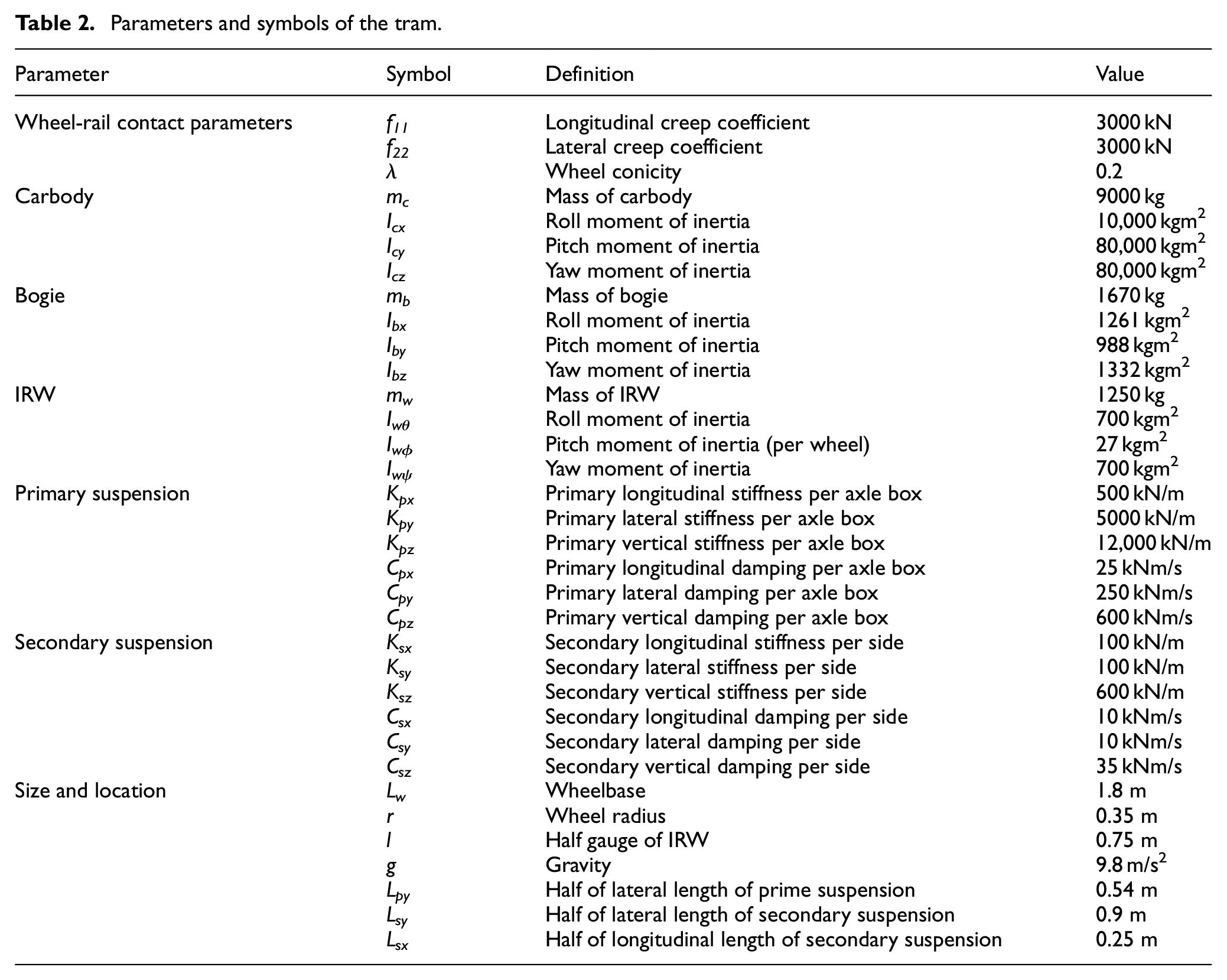
| Parameter | Symbol | Definition | Value |
|---|---|---|---|
| Wheel-rail contact parameters | f11 | Longitudinal creep coefficient | 3000 kN |
| f22 | Lateral creep coefficient | 3000 kN | |
| λ | Wheel conicity | 0.2 | |
| Carbody | mc | Mass of carbody | 9000 kg |
| Icx | Roll moment of inertia | 10,000 kgm2 | |
| Icy | Pitch moment of inertia | 80,000 kgm2 | |
| Icz | Yaw moment of inertia | 80,000 kgm2 | |
| Bogie | mb | Mass of bogie | 1670 kg |
| Ibx | Roll moment of inertia | 1261 kgm2 | |
| Iby | Pitch moment of inertia | 988 kgm2 | |
| Ibz | Yaw moment of inertia | 1332 kgm2 | |
| IRW | mw | Mass of IRW | 1250 kg |
| Iwθ | Roll moment of inertia | 700 kgm2 | |
| Iwϕ | Pitch moment of inertia (per wheel) | 27 kgm2 | |
| Iwψ | Yaw moment of inertia | 700 kgm2 | |
| Primary suspension | Kpx | Primary longitudinal stiffness per axle box | 500 kN/m |
| Kpy | Primary lateral stiffness per axle box | 5000 kN/m | |
| Kpz | Primary vertical stiffness per axle box | 12,000 kN/m | |
| Cpx | Primary longitudinal damping per axle box | 25 kNm/s | |
| Cpy | Primary lateral damping per axle box | 250 kNm/s | |
| Cpz | Primary vertical damping per axle box | 600 kNm/s | |
| Secondary suspension | Ksx | Secondary longitudinal stiffness per side | 100 kN/m |
| Ksy | Secondary lateral stiffness per side | 100 kN/m | |
| Ksz | Secondary vertical stiffness per side | 600 kN/m | |
| Csx | Secondary longitudinal damping per side | 10 kNm/s | |
| Csy | Secondary lateral damping per side | 10 kNm/s | |
| Csz | Secondary vertical damping per side | 35 kNm/s | |
| Size and location | Lw | Wheelbase | 1.8 m |
| r | Wheel radius | 0.35 m | |
| l | Half gauge of IRW | 0.75 m | |
| g | Gravity | 9.8 m/s2 | |
| Lpy | Half of lateral length of prime suspension | 0.54 m | |
| Lsy | Half of lateral length of secondary suspension | 0.9 m | |
| Lsx | Half of longitudinal length of secondary suspension | 0.25 m |
Handling Editor: Chenhui Liang
Declaration of conflicting interests
The author(s) declared no potential conflicts of interest with respect to the research, authorship, and/or publication of this article.
Funding
The author(s) disclosed receipt of the following financial support for the research, authorship, and/or publication of this article: This work was supported by the Research on Key Technologies of Intelligent Operation and Maintenance of Rail Transit [grant number 20090503100]; the Belt and Road International Laboratory of China-Laos Railway Engineering [grant number 21210750300]; and the Talent Introduction Start-up Fund of SIT [grant number 10120K226016-A06].