
Abstract
Bypass pipeline inspection gauges have the advantages of low cost and bringing no consumption in transportation efficiency and have been widely used in pipe cleaning, inspecting, and maintaining operations. The moving speed of bypass pipeline inspection gauges will seriously affect the results of the operations, so there are strict requirements on the moving speed of bypass pipeline inspection gauges. Because the moving speed of pipeline inspection gauge is difficult to measure or control in real time, it is important to predict it. This paper studies the influencing factors and their impact methods of pipeline inspection gauges’ motion. Through the combination of computational fluid dynamics simulation and friction mathematical model, the relationship between the value of the bypass hole diameter and the pipeline inspection gauges’ moving speed was studied. Under the selected research conditions, when the diameter of the bypass hole is increased from 0.1 to 0.5 m, the moving speed of pipeline inspection gauge in water and crude oil is, respectively, decreased from 2.779 to 0.589 m/s and from 2.777 to 0.373 m/s, and the relationship between them can be approximately described by a function. Based on this principle, the moving speed of pipeline inspection gauge can be predicted mathematically. The experiments also indicate that the density and dynamic viscosity of the transport medium and the deformation amount of the bypass pipeline inspection gauge sealing disk will affect the movement state of pipeline inspection gauge in the pipeline. This research has guiding significance for the design of the pipeline inspection gauges’ structure size, which is beneficial to the pipeline robot to better meet the needs of cleaning, inspecting, and maintaining operations, and has reference value for related researches.
Keywords
Introduction
Pipeline transportation has the advantages of low cost, large flow, continuous operation, and high safety. It is widely used in the transportation of crude oil, natural gas, and chemical products. However, with long-term use, the aging problems of oil and gas pipelines become more and more serious, and problems such as pipeline corrosion and impurity accumulation may occur. Various intelligent pipeline inspection gauges (PIGs) are required to perform dehydration, cleaning, and interior inspection operations to improve these efficiency and safety of pipelines. 1 Periodic cleaning of oil and gas pipelines using cleaning PIGs is the most suitable and efficient solution and has become the industrial standard procedure. 2 PIGs used to detect and maintain oil and gas pipelines also play an important role in the pipeline transportation industry. 3
PIGs are propelled by transport medium in the pipeline, when the transport medium is liquid and there is no bypass area on the PIG, and the velocity of PIG will be the same as the fluid. However, the pipeline operation has strict requirements on the speed of the PIG. Too low speed will affect the work efficiency of the PIG and the transportation efficiency of the pipeline. Too high speed may cause damage to the PIG or pipeline and the inspection data could be missed. It is necessary to analyze and predict the movement of PIGs to estimate their speed, position, and working conditions before the operation. Accurate assessment can greatly help operators control PIGs’ movement and reduce the risk of pipeline operations. 4
In order to ensure the moving speed meets the working requirements, a kind of device called bypass valve has been widely used to adjust the moving speed. It can change the flow field state in the pipe by changing the area and shape of the flow orifice to control the moving speed. 5 Unlike traditional PIGs with completely sealed pipes, the speed of the bypass PIG depends on the force acting on the PIG, instead of the fluid speed. When the bypass PIG has stable motion and steady speed, the driving force generated by the flow field to the PIG is equal to the friction generated by the contact between the PIG and the pipe. 6 The change in the speed of PIG will cause the change in the flow field in the pipe, that is, the driving force and friction force of PIG. Therefore, the speed of PIG is closely related to the friction force. It is important to study the friction force of the bypass PIG to estimate the moving speed.
McDonald may be the first person who proposes a mathematical analysis of the friction force on a pipeline robot in a gas–liquid pipeline. In 1964, he obtained an ideal mathematical model of the friction force on PIG through some simplifications. And in this model, some results are close to the results in actual operation. 7 In 1996, O’Donoghue A optimized the friction mathematical model. Taking the effect of PIG’s motion on the flow field and the force acting on the PIG into account, combining the theory of Winkler’s elastic foundation with Hertz contact principle, a classic friction mathematical model of PIG was established. 8 The mathematical model is simplified by considering the contact force between the PIG sealing disk and the inner wall of the pipe as a linear force, which makes it convenient to calculate with a degree of accuracy. In order to improve the accuracy of the calculated friction force, Zhu X et al. used a finite element analysis software to conduct a non-linear simulation study of the friction force on PIG and compared it with the linearized calculation results and actual test results. It shows that the accuracy of non-linear simulation research is higher than the accuracy of linear calculation. And it also verifies that the finite element method is feasible to analyze and predict the force state of PIG.9,10 In the research of Zhu X, the study on the influence of different flow field states on the friction is mainly realized by finite element simulation analysis, which guarantees extremely high accuracy and requires huge workload. To make it easy to research, this paper studies the friction force by a method of combining finite element analysis with mathematical model.
In actual work, when the bypass PIG is used for pipeline operation, changes in the fluid state can cause a pressure difference around the bypass valve. The pressure difference generates the driving force acting on the PIG. The driving force will affect the moving speed of the bypass PIG and it should be equal to the friction force when the moving speed is constant. 11 The magnitude of the friction force can be obtained by a combination of mathematical models and simulation software, and the calculation of the driving force can also be performed by finite element analysis software. 12 Mazreah et al. 13 have used finite element analysis software to study the mechanical effects of flow fields on PIGs and verified the accuracy and convenience of the method. Using finite element software to analyze the driving force, combining with the friction force model, it is convenient to predict the moving speed of the bypass PIG with different aperture sizes.
In this paper, the operation of the bypass PIGs when the medium is water and crude oil is respectively studied, and the effects of the density and dynamic viscosity of the fluid medium on the PIGs’ motion are also analyzed. By combining the computational fluid dynamics (CFD) simulation analysis and the mathematical model of friction force, the driving force and the friction force of the PIG at different bypass hole diameters and different moving speeds are obtained. Based on the principle that the driving force and the friction force are equal in a stable motion state, the relationship between the PIG’s moving speed and the bypass hole diameter is obtained.
Mechanics-mathematics model of PIG
Mathematical model of driving force
CFD modeling of flow field in pipeline
This paper regards the traditional pipe PIG as the research object, which consists of a sealing disk, a tightening disk, a separation disk, and a bypass hole. In the simulation experiment, the research object can be simplified as two sealing disks and a hollow cylinder. Based on PIG’s practical application in engineering, the diameter of the inner wall of the pipeline is selected to be 0.9868 m, the length of the bypass hole is 2 m, the diameter of the sealing disk is 1.025 m, the elastic modulus of the sealing disk is 4 MPa, the thickness of the sealing disk is 0.03 mm, and the diameter of the separating disk is 0.7 m. 9 Taking into account the computational complexity and calculation accuracy of the CFD simulation, 5-m-long flow field upstream of the PIG and 10-m-long flow field downstream of the PIG were taken as the research object, and the bypass hole diameter of 0.05–0.5 m is taken for simulation research. In this condition, the accuracy of calculation and data analysis is guaranteed, and the time cost is reduced.
The meshing of the flow field is completed by the software’s meshing module. The mesh is selected as a free tetrahedral mesh which has good adaptability. In order to ensure the accuracy of the simulation results, the mesh was processed with boundary layer, corner refinement, and key area mesh encryption. The cell amount is about 7.1 × 10⁵ and the average cell volume is about 2.3 × 10⁻⁵ m3. The result of mesh division is shown in Figure 1. In the simulation test, the wall in contact with the PIG is defined as a moving wall, and the movement of the PIG in the pipe is replaced by the movement of the wall. The flow rate of the transport fluid in this type of pipeline is almost constant, and the velocity of the fluid in the pipeline is about 2.8 m/s. Based on the flow field characteristics of the system, the boundary conditions of the system are set to speed inlet and pressure outlet type: the inlet speed is defined as 2.8 m/s and the outlet pressure is defined as 1 MPa, which considering the fluid flow in the pipeline is incompressible, in order to ensure the authenticity of the simulation and the degree of identification of the change in pressure difference in the flow field. The wall in contact with the PIG is defined as the moving wall, the moving direction is consistent with the direction of the liquid flow, and the moving speed is equal to the traveling speed of the PIG.
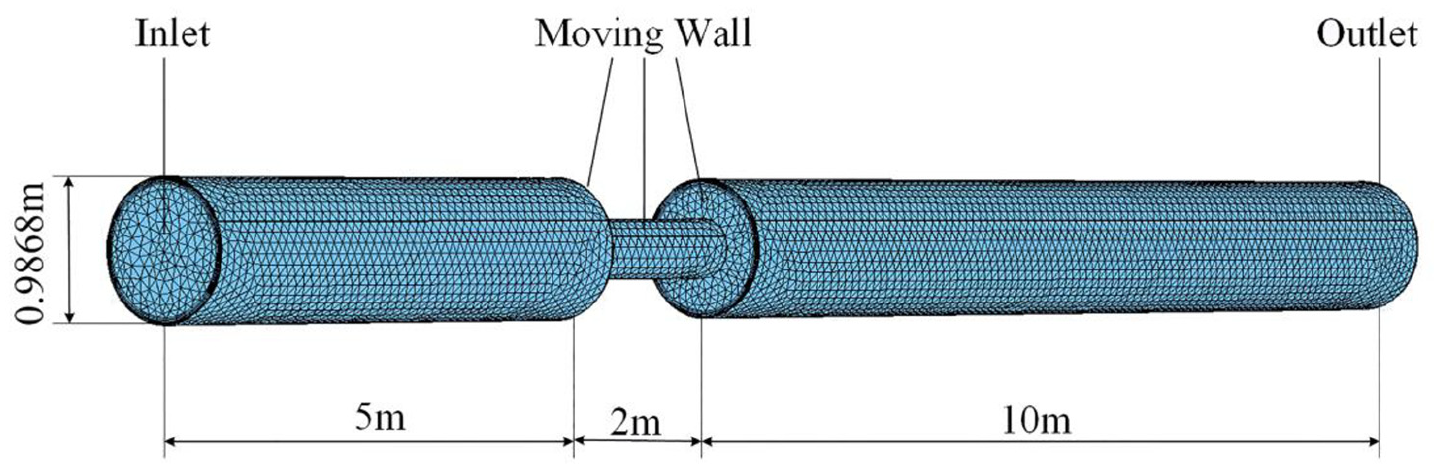
Meshing results of the flow field in the pipeline.
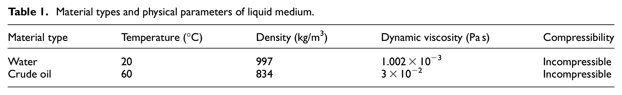
When PIG performs the cleaning operation, considering the effect of the operation, the transportation medium in the pipeline is usually water at 20 °C. When PIG performs inspecting and maintaining operations, considering the cost and efficiency of transportation and the physical properties of the transportation medium, the transportation medium in the pipeline is usually high-temperature crude oil. The crude oil object selected in this simulation is from Daqing Oilfield. The fluid materials and physical characteristics used in the simulation are shown in Table 1. The renormalization group (RNG) k-ε turbulence model was selected as the simulation model. 14
Material types and physical parameters of liquid medium.
Mathematical model of driving force
By post-processing the results obtained by the simulation, the pressure difference around the bypass PIG and the driving force acting on the PIG which generated by the pressure difference can be obtained. The liquid pressure state around the PIG and the projection of the end structure of the PIG are shown in Figure 2, where the red area means the sealing disk, the yellow area means the separation disk, and the blue area means the flowing liquid. The product of the average pressure difference
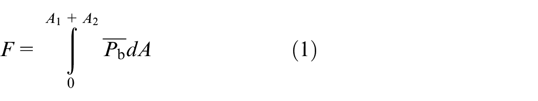
where F is the driving force acting on the PIG,
The pressure difference distribution around the bypass valve.
Grid independence test
In order to make sure the grid is good enough to have almost no effect on the simulation accuracy, the grid independence test is conducted. The case where the medium is water, the bypass hole diameter is 0.3 m, and the speed of the moving wall is 1 m/s, which is taken as an example; two kinds of grids with higher precision are used to verify the accuracy of the previously selected grid. The quantity of the two grids is 1,943,944 and 7,634,117, and the average cell volume is, respectively, 8.343 × 10⁻⁶ m3 and 2.127 × 10⁻⁶ m3.
The difference in driving force values is used to evaluate the quality of the selected grid. When the grid quantity is 709,045, 1,943,944, and 7,634,117, the driving force is, respectively, 2.2692 × 10⁵ N, 2.2492 × 10⁵ N, and 2.2391×10⁵ N. The result difference among the three kinds of grid is no more than 2%, and the previously selected grid is considered good enough to have almost no effect on the simulation accuracy.
Mathematical model of friction
During the operation of the PIG, the sealing disk will directly contact the inner wall of the pipe and deform, which will cause the friction force acting on the PIG. The friction force consists of two parts: f1 is generated by the pressure difference around the sealing disk and f2 is generated by the deformation of the sealing disk.
Analysis of friction force caused by pressure difference
The deformation of the PIG’s sealing disk and the effect of the surrounding pressure difference on it are shown in Figure 3.
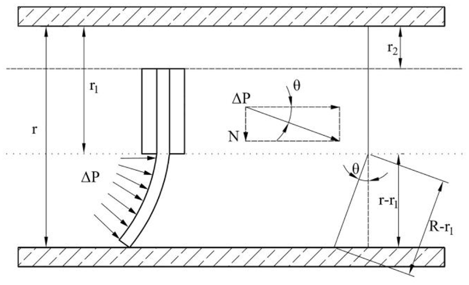
Distribution of the pressure difference acting on the sealing disk.
From Figure 3, the positive pressure acting on the pipeline inner wall N caused by the pressure difference can be expressed as

where ΔP is the pressure difference acting on the sealing disk, S is the area of the sealing disk, and θ is the angle between the liquid pressure direction and the axial direction of the pipeline

where μ is the coefficient of friction between the sealing disk and the inner wall, and the value is 0.5. 15
The value of the angle θ can be obtained from formula (4)
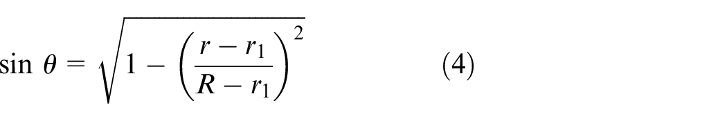
where R is the radius of the sealing disk, r1 is the radius of the separation disk, and r is the radius of the inner wall.
The area of the sealing disk S can be expressed as

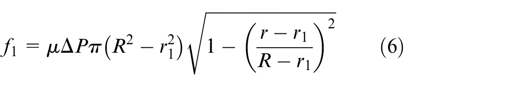
Bringing formulas (2), (4), and (5) into formula (3), the expression of f1 can be obtained as follows
Calculation of friction force caused by the deformation of sealing disk
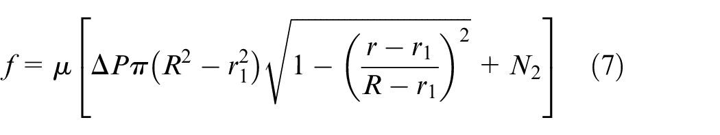
Since the diameter of the sealing disk is larger than the inner wall of the pipe, the sealing disk will deform in the pipe, which will cause a contact force between the inner wall and the PIG. This contact force will form a frictional force f2, which hinders PIG movement. Scholars usually use mathematical models or finite element simulation analysis to calculate this friction. O’Donoghue and Aidan 8 and A Den Heijer 16 used Winkler’s elastic foundation theory and Hertzian contact equation, treated the sealing disk as a linear elastic material to simplify the stress of the sealing disk, and derived the mathematical formula of friction. However, the formula is relatively harsh on the using condition, and the definition of rubber as a linear elastic material also results in some error between the calculation result and the actual situation. In order to solve this problem, Professor Zhu used the finite element simulation analysis method to conduct a non-linear simulation of the contact force caused by the elastic deformation of the sealing disk. The experimental result is closer to the actual situation than the theoretical calculation. As the theme of this article is not focus on the simulation calculation of the radial pressure generated by the deformation of the sealing disk, Zhu’s research data were used directly in this paper. In the case studied in this paper, the contact force between a single sealing disk and the inner wall is about 2.4 × 10⁴ N according to Zhu et al.’s 9 research. There are two sealing disks in the motion system established in this paper, so the contact force N2 between the PIG and the inner wall caused by the deformation of the sealing disk is about 4.8 × 10⁴ N. The formula for calculating the total friction of the PIG is as follows
Through CFD simulation analysis and mathematical model calculation of friction force, the values of driving force and friction force at different PIG’s moving speeds with different bypass aperture sizes can be obtained. When the two forces are balanced, the PIG moves steadily, and the moving speed is regarded as the actual moving speed.
Calculation results and analysis of driving force and friction force
Driving force
When the bypass aperture is 50, 100, 150, 200, 250, 300, 350, 400, 450, and 500 mm, the PIG is in a static state and the speed is 0.2, 0.4, 0.6, 0.8, 1, 1.2, 1.4, 1.6, 1.8, 2, 2.2, 2.4, and 2.6 m/s, the CFD simulations were carried out. Taking aperture of 500 mm as an example, the velocity and pressure cloud pictures of the flow field are shown in Figure 4.
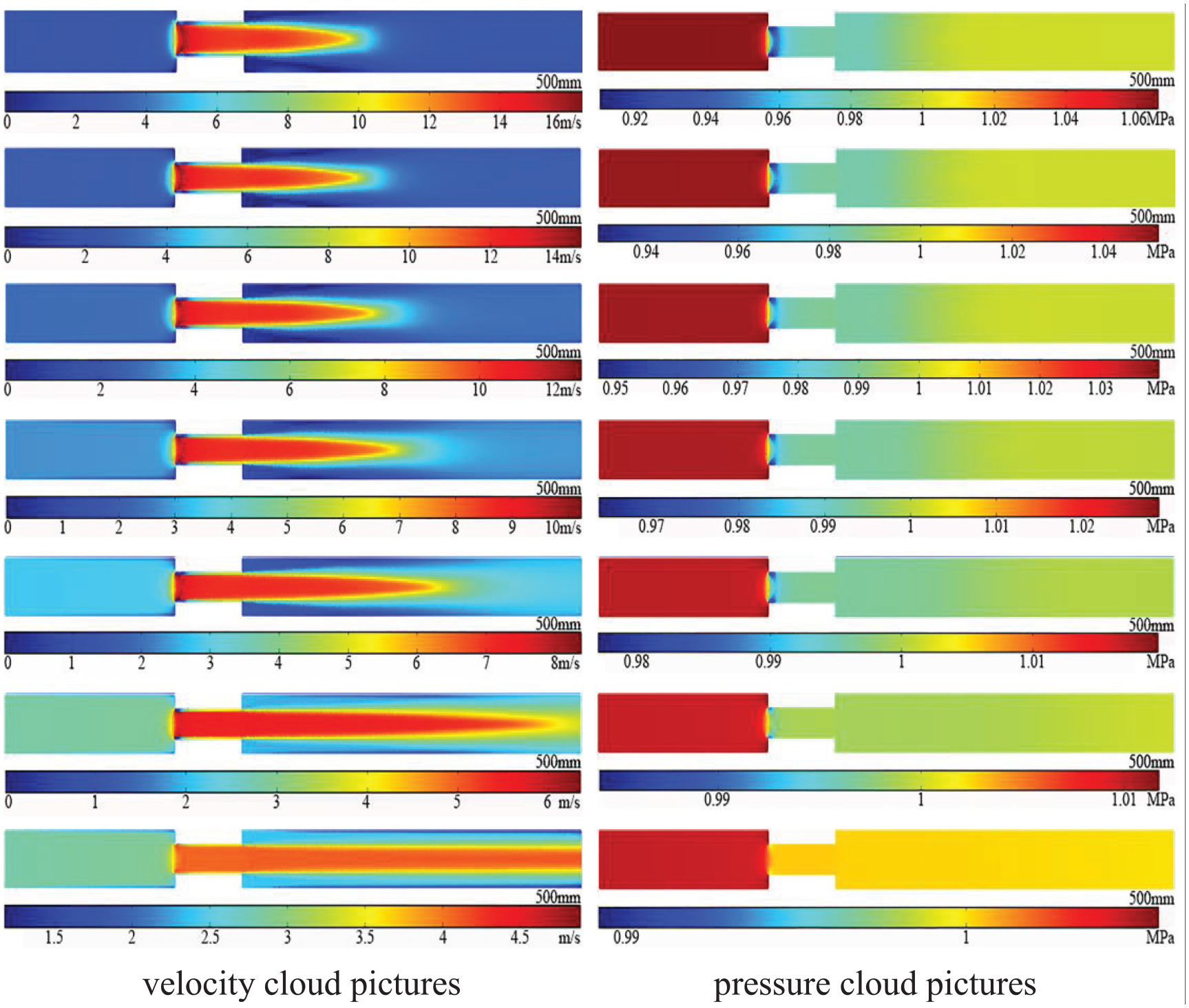
The velocity and pressure cloud pictures of the flow field at different moving speeds. The moving speeds are 0, 0.4, 0.8, 1.2, 1.6, 2, and 2.4, respectively, from top to bottom.
According to the simulation results, when the fluid flows through the bypass valve, a core high-speed region will generate. In this region, the velocity is maximum on the axis and decreases in the radial direction. The maximum speed occurs at the inlet of the bypass valve; this area will expand slightly after exiting the bypass valve, and the speed will decrease rapidly to the inlet speed. The speed in this area decreases as the PIG’s moving speed increases. When the PIG is stationary, the maximum speed in the core high-speed area is 16.5 m/s, and when the PIG’s speed is 2.4 m/s, the maximum speed in the core high-speed area is 4.8 m/s. Observing the pressure distribution cloud picture, it can be seen that the pressure distribution in the flow field changes with the change in the speed of the PIG. Same as the velocity cloud pictures, there is a low-pressure region on the core high-speed region at the entrance, and this phenomenon conforms to Bernoulli’s principle. Integrate the liquid pressure on the moving walls on both sides of the PIG to obtain the driving force of the PIG. Considering that the magnitude of the driving force is too large when the bypass hole is small, when the medium is water and crude oil, respectively, the curves of the driving force as a function of speed with bypass aperture of 0.2–0.5 m are plotted in Figures 5 and 6.
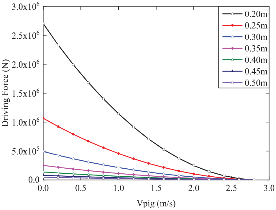
Curve of driving force as a function of moving speed (water).
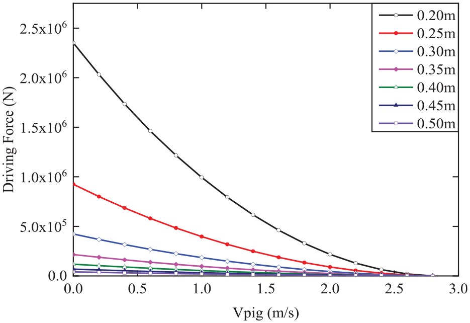
Curve of driving force as a function of moving speed (crude oil).
These images show that the driving force acting on the PIG is affected by the speed and the diameter of the bypass hole:
Under the same bypass hole diameter, the driving force decreases with the increase in the moving speed, and it decreases to 0 when the moving speed of the PIG is the same as the flow velocity of the fluid in the pipe. Taking the case where the medium is water and the bypass aperture is 0.3 m as an example, when the PIG’s moving speed is 1 m/s, the driving force is 2.14 × 10⁵ N, and the slope of the driving force with the speed is −2.18 × 10⁵ N s/m. When the PIG’s moving speed is 2 m/s, the driving force is 5.19 × 10⁴ N, and the slope of the driving force with the speed is −1.08 × 10⁵ N s/m. It can be seen that the tendency of the driving force to change with speed slows down as the speed increases. The cause of this phenomenon can be explained by Bernoulli’s principle and related knowledge of fluid mechanics. When the difference between the moving speed of the PIG and the speed of the fluid in the pipe increases, the more fluid flows through the bypass valve per unit time, and the greater the fluid velocity in the high-speed region, the greater the energy loss caused by the speed change. This phenomenon leads to increase in pressure difference around the PIG, and the driving force also increases.
When the PIG’s moving speed is constant, the driving force will decrease with the increase in the bypass aperture. Taking the case where the medium is water and the moving speed is 1 m/s as an example, when the bypass aperture is 0.2 m, the driving force is 1.14 × 10⁶ N, and the slope of the driving force with the aperture is −2.51 × 10⁷ N/m. When the bypass aperture is 0.4 m, the driving force is 6.29 × 10⁴ N, and the slope of the driving force with the aperture is 7.14 × 10⁵ N/m. It can be seen that as the bypass aperture increases, the driving force decreases, and the decreasing tendency slows down as the aperture increases. There are two reasons for this phenomenon: On one hand, a larger bypass hole diameter means a smaller force bearing area on the PIG, which results in less driving force for PIGs with larger bypass hole diameters under the same pressure difference. On the other hand, when the moving speed is the same, the flow rate passing through the bypass valve is the same. According to the relevant knowledge of fluid mechanics, it can be known that when the flow rate is constant, the smaller the flow passing area is, the more drastically the flow state of fluid at the inlet and outlet of the valve is. It causes the fluid to generate more energy loss as it passes through the bypass valve, which in turn produces a larger pressure drop and a greater driving force.
Friction force
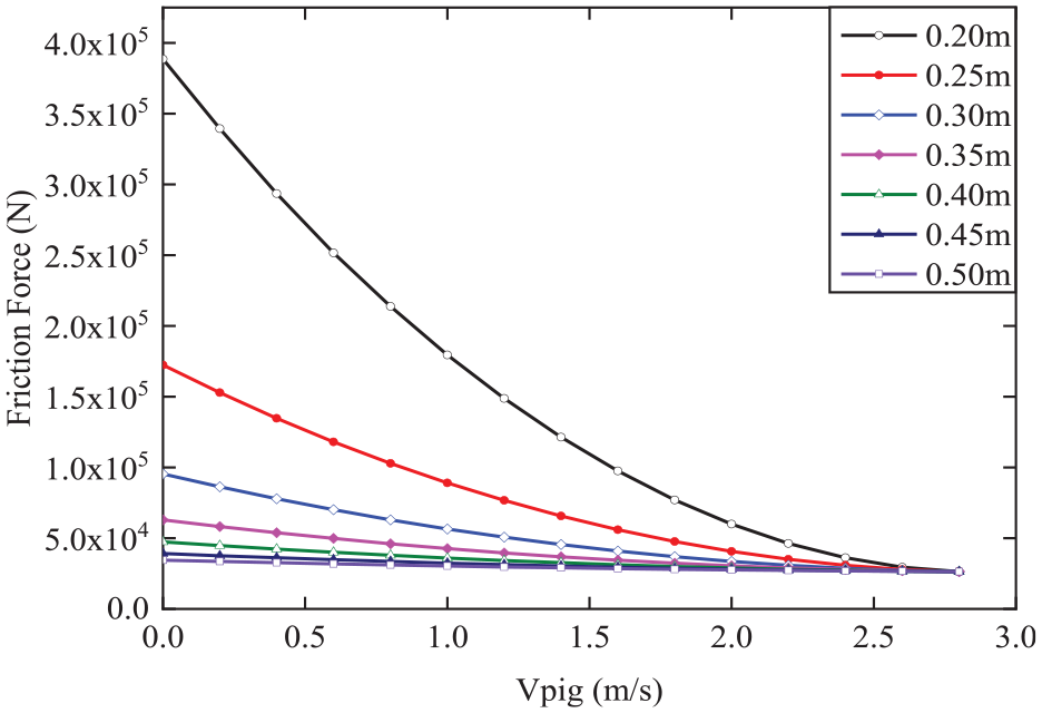
It can be known from formula (6) that the friction force depends on the pressure difference around the sealing disk. From the CFD simulation, it can be known that the pressure difference acting on the sealing disk changes with the change in the hole diameter and PIG’s moving speed. The average pressure difference acting on the sealing disk is brought into the friction force calculation formula (7), and the relationships between the frictional force and the speed with different bypass hole diameters are shown in Figures 7 and 8.
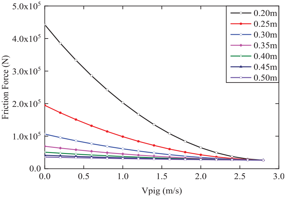
Curve of friction force as a function of moving speed (water).
Curve of friction force as a function of moving speed (crude oil).
Analysis of the calculation formula and the images of the friction force shows that the friction force is affected by the speed of movement, the diameter of the bypass hole, and the amount of deformation of the sealing disk:
When the bypass hole diameter is constant, the friction force decreases with the increase of the moving speed and decreases to the minimum value f2 when the moving speed is the same as the flow velocity in the pipeline. Taking the case where the medium is water and the bypass aperture is 0.3 m as an example, when the PIG’s moving speed is 1 m/s, the magnitude of the friction force is 6.12 × 10⁴ N, and the slope of the friction force with speed is −3.55 × 10⁴ N s/m. When the PIG’s moving speed is 2 m/s, the magnitude of the friction force is 3.47 × 10⁴ N, and the slope of the friction force with the speed is −1.29 × 10⁴ N s/m. The tendency of the friction force with the speed decreases as the speed increases. The reason for this phenomenon is consistent with the reason that the driving force decreases with increasing moving speed.
When the PIG’s moving speed is constant, the frictional force will decrease with the increase in the bypass aperture. Taking the case where the medium is water and the moving speed is 1 m/s as an example, when the bypass aperture is 0.2 m, the magnitude of the friction force is 2.03 × 10⁵ N, and the slope of the friction force with the bypass aperture is −3.1 × 10⁷ N/m. When the bypass aperture is 0.4 m, the magnitude of the friction force is 3.75 × 10⁴ N, and the slope of the friction force with the bypass aperture is −6.13 × 10⁵ N/m. It can be seen that as the bypass aperture increases, the friction force acting on the PIG decreases, and the decreasing tendency decreases as the bypass aperture increases. This phenomenon is also caused by the smaller bypass hole diameter, which results in a larger pressure difference.
By comparing formulas (2) and (6), it can be known that when the pressure difference changes, the change in the driving force is greater than the change in the friction force. Based on this principle, the reason why the moving speed of PIG can be controlled by changing the diameter of the bypass hole of the bypass valve could be explained. When the diameter of the bypass hole decreases, the pressure difference around PIG increases, resulting in a greater driving force than friction. The difference between the driving force and the friction force causes the increase in moving speed to a value which meets the condition that the pressure difference decreases to a level making the driving force equals to the friction force.
The amount of deformation of the sealing disk will affect the amount of friction, and PIGs with a larger amount of deformation will bear greater friction under the same pressure difference. Combining the phenomenon mentioned in conclusion (3), a corollary can be drawn: when the bypass valve through-hole diameter is constant, the PIG with a larger deformation of the sealing disk needs a larger pressure difference during stable movement and the moving speed is lower.
Relationship between the moving speed and the bypass hole diameter
When the medium is water, the curves of the driving force obtained by the simulation and the friction force calculated by the mathematical model under different bypass hole diameters as a function of speed are, respectively, drawn in Figure 9. The point of intersection means the force equilibrium state, and the value of abscissa equals to the moving speed at this aperture. The curves of the moving speed with the changes of the aperture are drawn and fitted by a polynomial function fitting method, and the results are shown in Figure 10.
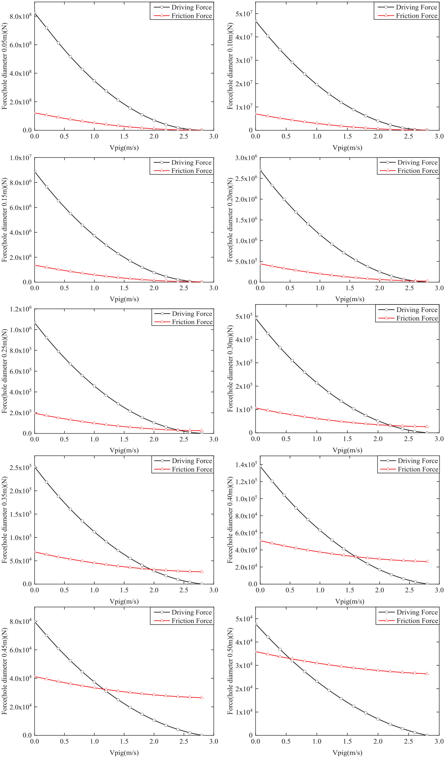
Relationship between the driving force and friction force of the PIG with different apertures at different moving speeds.
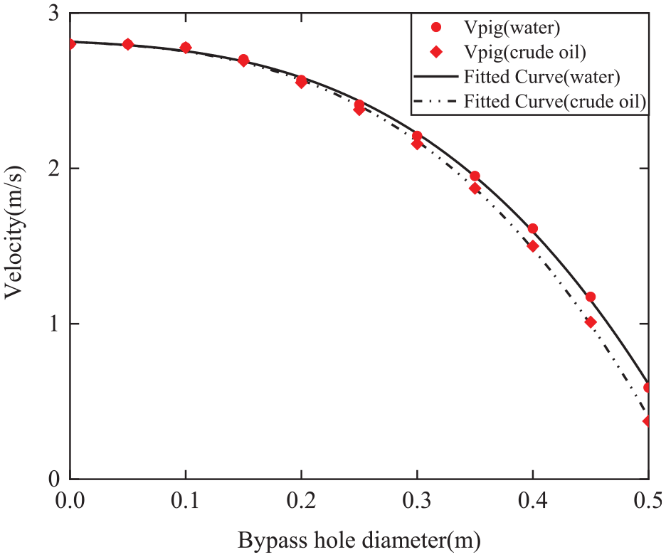
Curves of moving speed of the PIG as a function of bypass hole diameter.
The resulting fitted function is

where v is the PIG’s moving speed and d is the value of bypass hole diameter. When the medium is water, A = −13.4 m/s, B = −1.4818 m/s, C = −0.3172 m/s, and D = 2.8144 m/s. When the medium is crude oil, A = −14.972 m/s, B = −1.5134 m/s, C = −0.3332 m/s, and D = 2.8147 m/s.
It can be known from the analysis of the obtained curves and fitted functions:
The material will affect the motion state of the PIG. When the bypass aperture is 0.2 m, the moving speed of the PIG in water is 2.568 m/s, and the moving speed of the PIG in crude oil is 2.552 m/s. When the aperture is 0.4 m, the moving speed of the PIG in water is 1.613 m/s, and the moving speed of the PIG in crude oil is 1.5 m/s. According to the data analysis, it can be found that in the range of 0.05–0.5 m bypass hole diameter, the moving speed of the PIG in water is greater than it is in crude oil. When the aperture is 0.2 m, the speed difference between the two is 0.016 m/s, and the slope of the speed difference with the aperture is 0.228 s−1. When the aperture is 0.4 m, the speed difference between the two is 0.113 m/s, and the slope of the speed difference with the aperture is 0.823 s−1. It can be seen that the speed difference increases with the increase in the aperture. This is due to the different physical properties of water and crude oil, which are mainly related to the density and dynamic viscosity of the medium. According to Bernoulli’s equation, the lower the density of the fluid, the smaller the pressure drop caused by the increase in speed. Similarly, the lower the dynamic viscosity, the lower the resistance to flow inside the fluid and the smaller the energy loss and pressure drop of the fluid flowing through the bypass valve. It can be known from the previous analysis that a decrease in the pressure drop will cause a reduction in the moving speed of the PIG.
When the medium is constant, the moving speed of the PIG depends on the diameter of the bypass hole. The larger the diameter of the bypass hole, the smaller the moving speed of the PIG. When the medium is water, the moving speed of the PIG with 0.2 m bypass hole diameter is 2.568 m/s, and the slope of the moving speed with the bypass hole diameter is −1.23 s−1. When the diameter of the bypass hole is 0.4 m, the moving speed of the PIG is 1.613 m/s, and the slope of the moving speed with the bypass hole diameter is −7.93 s−1. It can be seen that the moving speed decreases with the increase in the bypass aperture, and the decreasing trend also increases as the bypass aperture increases. According to the calculation of the fitted formula, it can be known that when the medium is water and the bypass hole diameter is about 0.547 m, the moving speed of the PIG approaches 0, and the effective adjustment range of the bypass hole diameter is 0–0.547 m. When the medium is crude oil and the diameter of the bypass hole is about 0.528 m, the moving speed of the PIG approaches 0, and the effective adjustment range of the diameter of the bypass hole is 0–0.528 m. It can be known that when the density and dynamic viscosity of the pipeline transport medium are known, the value of the bypass aperture can be used to predict the moving speed of the PIG in the pipeline by using mathematical methods.
Summary
In the constant flow pipelines, different moving speeds of the fluid-driven type bypass PIGs can be obtained by changing the diameter of the bypass hole. In this article, a CFD model of PIG motion under the action of pipeline fluid is established to obtain the pressure distribution, and then, the driving force model and friction force model are established. Taking the fluid-driven-type bypass PIG as the research object, the driving force and friction force of PIGs in the pipeline when the fluid medium was water and crude oil were analyzed, respectively. The simulation analysis shows that under different bypass apertures, the driving force and friction force both decrease with the increase in the moving speed, and on the force–speed curve, the absolute value of the slope of the driving force reduction is much larger than the friction force. When the medium is water, the bypass hole diameter is 0.3 m, and the PIG’s moving speed is 1 m/s, the slope of the driving force with the moving speed is −2.18 × 10⁵ N s/m, and the slope of the friction force with the moving speed is −3.55 × 10⁴ N s/m. Under different bypass hole diameters, there must be a moving speed that makes the driving force equals to the friction force, and the moving speed decreases with the increase in the bypass hole diameter. The fluid medium has an effect on the relationship of PIG’s moving speed with the bypass hole diameter. When the diameter of the bypass hole is increased from 0.1 to 0.5 m, the moving speed of PIG in water and crude oil is, respectively, decreased from 2.779 to 0.589 m/s and from 2.777 to 0.373 m/s. The PIG’s moving speed–bypass hole diameter function relationship was obtained through a polynomial fitting. In this way, the PIG’s moving speed of various bypass hole diameters can be predicted. And according to the required PIG’s moving speed, it can provide guidance or basis for bypass hole design.
Footnotes
Declaration of conflicting interests
The author(s) declared no potential conflicts of interest with respect to the research, authorship, and/or publication of this article.
Funding
The author(s) disclosed receipt of the following financial support for the research, authorship, and/or publication of this article: This work was supported in part by the National Natural Science Foundation of China under Grant U1908228 and 51475064, in part by the Science and Technology Innovation Fund Project of Dalian under Grant 2019J12GX041, and in part by the Fundamental Research Funds for the Central Universities of China under Grant 3132019351.