
Abstract
This research work has been completed by concentrating on the structure of inserts for foot orthosis fabricated by utilizing rapid prototyping technology. Thermoplastic elastomer and thermoplastic polyurethane are the most commonly used materials that are being used in customized three-dimensional printed orthotic insoles, which are comfortable and prevent the user in many foot disorders. Thermo-softening viscoelastic polymers, explicitly Filaflex and Ninjaflex, have been printed by utilizing Flash Forge three-dimensional printers to evaluate the mechanical properties of specimens with alterations of the percentage rate fill-up design replicas. The results are compared on the basis of hardness test, flexural/bending test, and tensile test using Durometer and Universal Testing Machine (UTM). It has also been observed that the most significant effecting factor is infill density.
Keywords
Introduction
The interface between the human and product has become an important parameter for the design of any product, and if neglected, it may result in some disorders, injury, pain, or discomfort. The footwear is a very special product as it carries the whole weight of human body and has a vast range of varieties in respect to comfort. Due to these factors and importance of comfort and to prevent injuries, the concept of customized-designed orthotic insoles has gained huge popularity in a short span of time. 1 Orthotic insoles are commonly utilized for additional comfort and to help the foot torment, shin torment, heel torment, and back torment. Generally, a biomechanical malalignment or instability from the foot area creates irregular loads on the heel point, tissues of foot, shin, and knee, which subsequently may lead to back torment.2–4 Customized-designed orthotic insoles are used to relieve plantar pressures. The thermoplastic polyurethane (TPU) comprises a two-phase microstructure, which consists of a hard segment. The hard phase provides the base for its mechanical properties. It provides advantage in chemical resistance, abrasion, blood, and tissue compatibility, thus making it a very essential group of polyurethane group.5–7 The thermoplastic elastomers (TPEs), on the contrary, are frequently used in harsh environmental conditions, that is, under high-temperature deviations and cyclic loading conditions. TPE is a new class of materials which can be studied more, as very less literature is available on this material. It has been found that the three-dimensional (3D) printed orthotic insoles are relatively new area for research, and very less prominent conclusions have been found till date.
In general, Selective Laser Sintering (SLS) and Fused Deposition Modeling (FDM) are two additive manufacturing techniques used in the production of orthotic insoles. The SLS technology has been very rarely used in this area although some prominent results were concluded by some researches made using different composite materials. 1 Two footing plans for development of insoles were compared in Figure 1. The primary sole unit (SLS-A) uses footing highlights dependent on the stick and needle spike shape. The pins have base diameter of 5 mm and a stature of 4 mm. About 80 footing highlights are there for every underside section. In second plan (SLS-B), Christmas tree molded spikes were used. These footing highlights had a basic platform measurement of 6 mm and a stature of 4 mm. An aggregate of 30 footing highlights per bottom unit was used. Both the sole units were taken from SDS 606 dash shoe upper, UK estimate 9.2,3
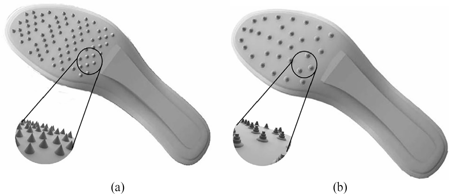
(a) Primary sole unit (SLS-A) and (b) secondary sole unit (SLS-B) traction blueprint on the Selective Laser Sintering insole entities. 1
After the underlying test preliminaries, the secondary sole unit, SLS-B sprint shoe was ejected from additional testing due to rupture/crack of a few of the traction attributes. The outcomes for remaining three sprint/dash shoes were offered as an average of four preliminaries. The researcher demonstrates the even power reported through uprooting of these print shoes at a distance of 100 mm on the different dimensions of ordinary stacking. The outcomes show that SLS-A dash shoe can produce footing powers steady with the financially accessible run shoes tested, over the dimensions of ordinary stacking analyzed. At lower dimensions of typical burden, the key concern was skidding of the dash shoe with respect to the trace surface. The outcomes, in any case, had not given a proof that SLS-A run shoe would be bound to slip amid a run keep running than the monetarily accessible dash shoes. 1
The main objective found in the researchers focused on the comfort and the life of the used orthotic insole while some laid stress on the prevention of injury and providing relief from knee, heel, and shin pain. Kumar investigated SLS focused on the dimensional accuracy of the insole produced by the process of SLS. The laser used was CO2 with power wattage of 25 to 100 watts. 5 The parameters that shift in SLS incorporate powder estimate, scan speed, powder density, beat recurrence, fill laser control, check measure, examine dispersing, part-bed temperature, layer thickness, laser control (execution), laser vitality, spot estimate, powder measure circulation, proportion of the powders of the blend, and folio volume portion. Sintering was carried on the DTM sinter station, and different factors, for example, roller travel speed, construct stature, part volume, and part-bed temperature, were additionally considered. Manufacturing introduction and pressing were vital parameters for ideal use of the restricted form tank space and to diminish construct time, which could be accomplished through a base left methodology and utilizing hereditary calculation. In 2005, Helbert used 3D printable materials, namely, gypsum and starch. The completed sockets were filled in with a resin to improve strength and reinforced with a carbon fiber wrap. 4 Faustini et al. 8 proposed a framework for transtibial sockets production using SLS and Duraform™ material. The thermoformed materials are also a common material among socket design. Its customization is often made with a plaster cast of the residual limb. Thermoformed material is heated at 300°C to 400°C and then molded to the plaster using vacuum pressure in order to assure a proper fit. 9 Sanders et al. 10 have used the sockets made of polyethylene terephthalate glycol and polyester. LIM Innovations owns the Infinite Socket TF™, a versatile custom-molded socket able to suffer some adjustments to accommodate daily stump volume fluctuation. 11 First, hand-held scanners used a probe to scan the touched surface. For that, the position of the probe needs to be determined by a certain type of computer-controller 3D location measurement aid. 12 Vannah et al. 13 introduced an alternative method in which a hand-held scanner is operated in a continuously sampling mode and showed its applicability in the reproduction of a residual transtibial limb. Kai et al. 14 used facial prosthetic model fabricated by a 3D scanning, to acquire facial geometry, and have chosen 3D SCAN among the conventional method of Plaster of Paris, magnetic resonance imaging (MRI), and computed tomography (CT). Several authors, such as Bibb, Chua, and Surendran, 15 suggested the use of a reverse engineering (RE) software to perform the post-processing of 3D scanned data. Fernandes et al. 16 also used 3D scan technology to acquire anthropometric data to develop an ankle foot orthosis. The procedure was made with two laser scanners and it was capable of capturing intricate zones. 15 To solve the problem of sustaining a fixed position during scanning procedure, an approach of applying the patch-wise as-rigid-as-possible deformable alignment technique was described by Bonarrigo et al. 17 in 2014. Baronio et al. 18 also used an optical 3D scanner to acquire wrist and hand shapes to build a hand orthosis, as illustrated in Figure 2. Currently, a number of commercial hand-held scanners are available in the market, such as BioSculptor, NextEngine 3D Laser Scanner, CAPOD, Tracer-CAD, and VORUM companies.19,20
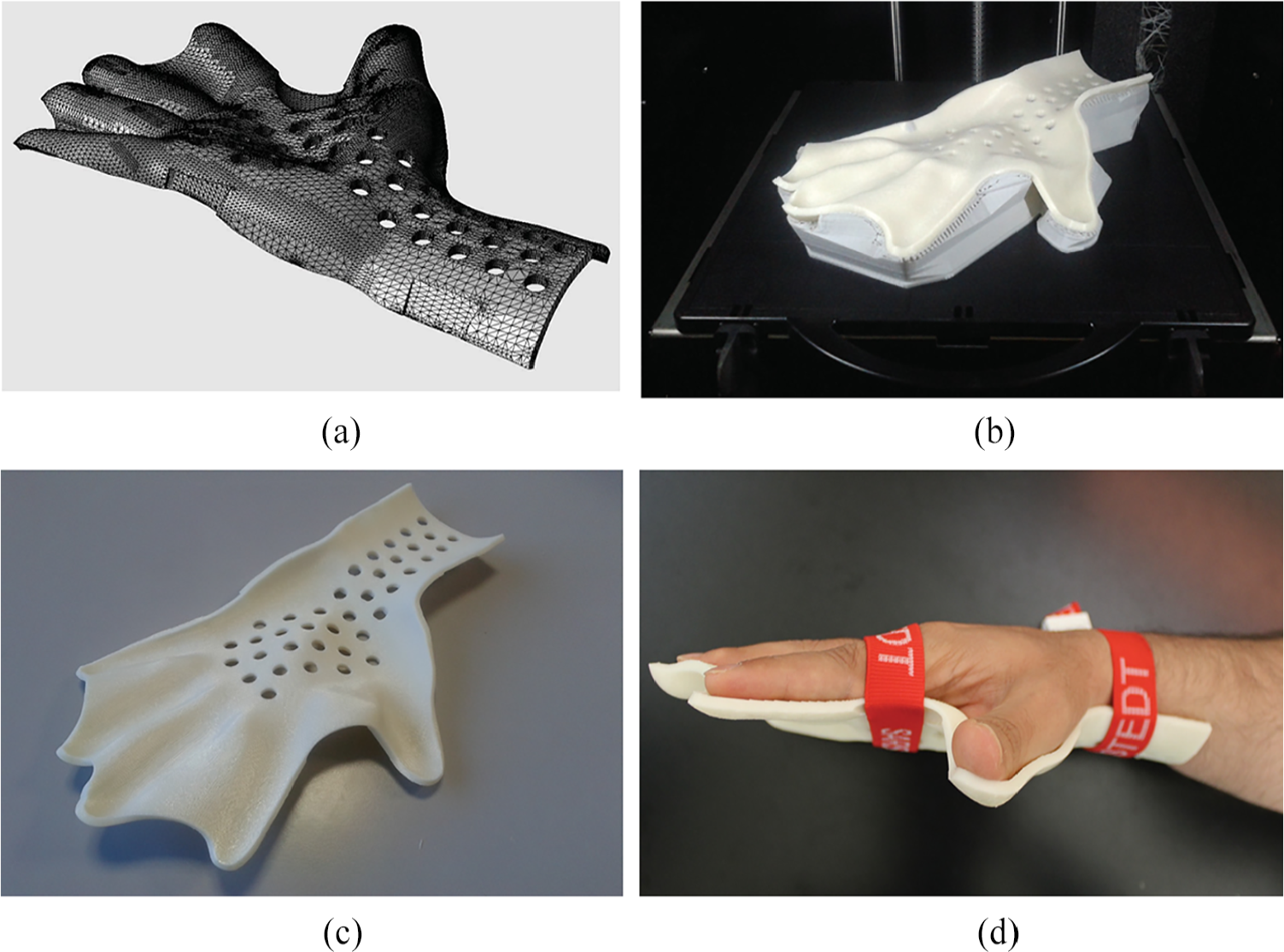
3D printing phase of hand orthosis. 18
Faulkner and Walsh 21 showed its applicability to design prosthetic sockets in 1989. A supercomputer system was used to read data and to produce a 3D image of the stump, as shown in Figure 3. 22
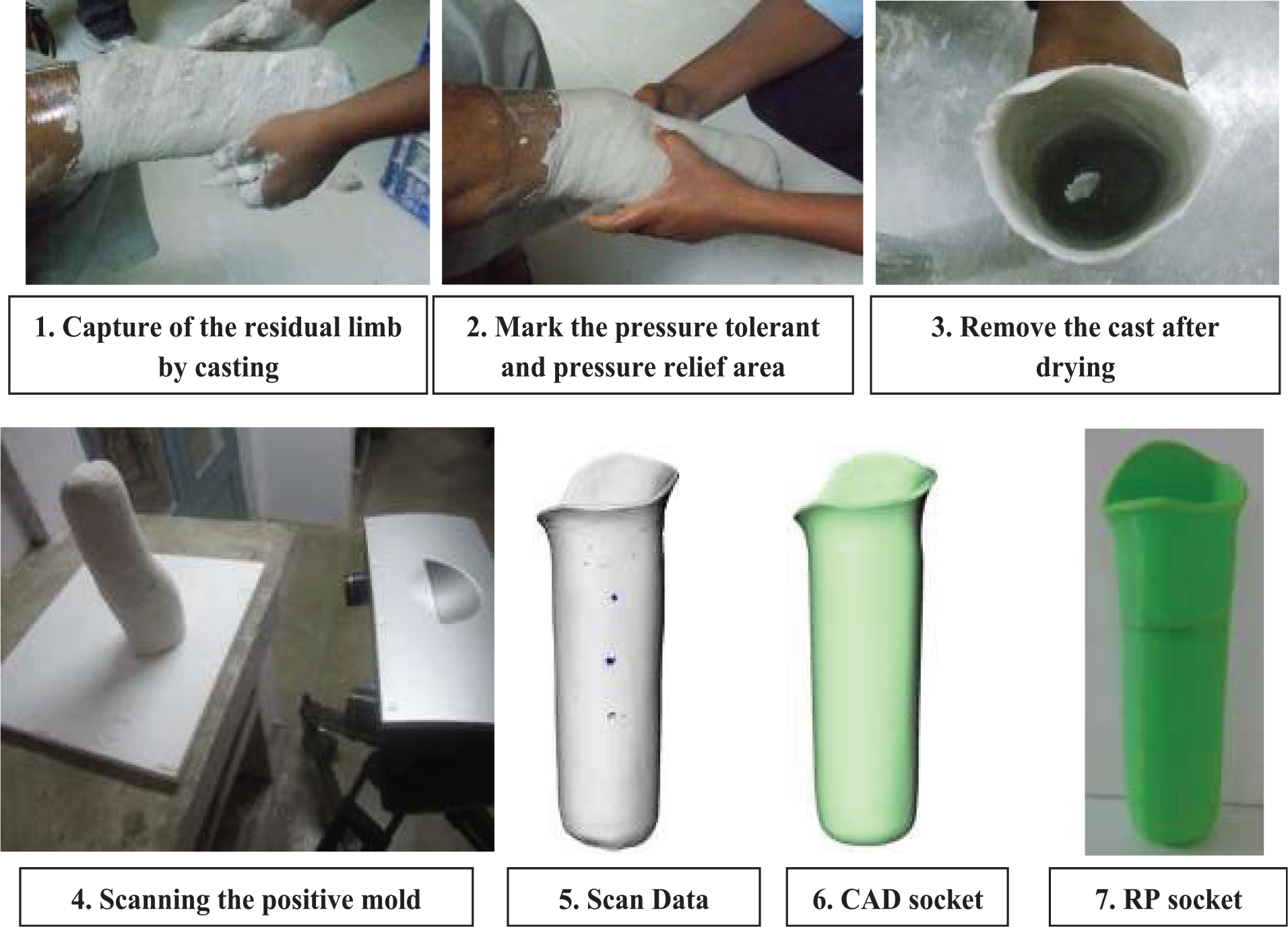
Manufacturing of prosthetic sockets using rapid prototyping technology. 22
Smith et al. 23 verified in 1995 that CT offers stump acquisition with fewer errors than hydrostatic weighing methods and optical surface scanning. Zheng et al. 12 reported that Zachariah in 1996 and Commean in 1997 employed 3D volumetric images obtained by CT to define a finite element method (FEM) for the residual limb to perform an interface analysis. In particular, Commean et al. 24 developed an analysis of limb stump slippage within the prosthesis. Besides that, in 1998, the author created measurement and visualization methods to evaluate residual limb shape changes after donning and loading prosthesis. 25 As Smith et al. 23 referred, Szabo also deployed CT data to produce an FEM analysis. Nayak mentioned that Shuxian in 2005 presented an approach based on CT and image processing where the 3D structure of internal bones and skin constituting the patient residual limb was derived from tomographic images. In addition to this, Shuxian also proposed in 2005 an approach for 3D residual limb reconstruction for prosthetic socket customization. The suggested methodology includes CT scanning to access bone and skin structure of the stump, which would allow the prosthetist to perform socket design with the help of the visualized internal structure and its external shape. 20 Gravitational forces can also distort the position of stump soft tissues relative to the skeletal structure. To decrease this, Torres-Morenol, in 1999, acquired the residual limb structure with a plaster shell made by a prosthetist. 12 Before that, Douglas et al. 26 verified in 1998 that MRI data of bone and skin surface are also suitable to define the FEM for computational analysis. Its application in stump geometry acquisition is still limited to mostly research purposes and to static analysis. 12 Fernie related in 1985 about a shape fitting process simulated by computer-aided prosthetic fitting software developed by the University of British Columbia. The referred software allowed modifying a “primitive” socket shape to match a certain stump shape and size. 27 Saunders et al. 28 also suggested in 1985 a computer-aided sculpting system for use in prosthetics. Walsh et al. 29 designed and developed in 1989 a CAD/CAM (Computer aided design/Computer aided manufacturing) system capable of producing prosthetic devices for developing countries, where technicians may not have all of the equipment that a modern prosthetic facility had in those years. In 2001, Rogers et al. 30 published a socket evaluation where this element was designed with ShapeMaker prosthetic CAD software. An Italian Research Project named DESPRO (DESign and Develop Custom-fit Products: Application and validation for a Socket of a Lower Limb PROsthesis), funded by Italian Research Ministry and introduced by Frillici, correlates FEM and CAD to simulate the biomechanical interaction between the socket and the stump of the patient. However, FEM integration in these fields seems more important for lower limb devices. 31 Scheck & Siress 32 offers a CAD and CAM system to produce sockets. RODIN4D offers a range of products to make orthopedic devices, namely, 3D SCANNERS, RODIN4D software, a 3D printer, and some additional accessories. RODIN4D, paid software, allows the production of orthosis and prosthesis with some spline manipulations of the geometrical shapes available in its library. 33 VORUM also presents a methodology to prototype a customized prosthetic device. It starts from 3D scan, then goes to CAD software to modify the form, and it ends on mold fabrication or on a rapid prototyping (RP) technique. 34 BioSculptor Company designs, manufactures, and sells solutions also based on CAD and CAM technologies. BioSculptor owns BioScanner™ and Bioshape software. The referred software is paid and allows modifying orthosis and prosthesis. 35 LIM Innovations presents LIM capture, an approach to achieve a well-fitting, custom-molded socket using measurements and images to develop the 3D digital stump and then to define a customized infinite socket TF™. 11 Davies et al. 36 related in 1985 the rapid form process—an RP machine—for an automated thermoplastic socket production. Northwestern University, in collaboration with Baxter Healthcare, made a single transtibial socket using Stereolithography apparatus (SLA) in 1990. 30 Regarding socket reproduction, Cheng 9 verified, in 1998, that this technique seems suitable to manufacture both positive plaster cast and socket. Cugini suggested an approach to fabricate a lower limb socket with RP technologies. This methodology included stump measurements, CAD reconstruction, socket design, and socket rapid manufacturing. Northwestern University and Baxter Healthcare developed in 1990 a transtibial socket using stereolithography (SLT). 37 Rogers et al. 38 suggested in 1991 a method to produce transtibial sockets with SLS technique. In 1992, Rovick developed an RP technique named Squirt Shape to fulfill the need for producing prosthetic sockets at high velocity. In this technology, a single wall socket was formed of an FDM of molten plastic. 37 Rovick also proposed in 1994 an additive fabrication technique for the CAM of prosthetic sockets. The RP machine prototype was designed by the authors, and it was suitable to work with common thermoplastic materials such as acrylonitrile butadiene styrene (ABS). 39 In 1998, Lee reported on fabricating two prosthetic sockets using FDM. 30 In 2000, Rogers et al. 40 published an article about a sophisticated double-wall socket fabricated using SLS. During 2003, Monash University employed FDM to integrate sockets with cosmetic covers. Its alignment was performed in software. 37 Comotti developed a method that has used the 3D printer with dual extrusion capabilities, and the socket was printed with Polylactic acid or Polylactide (PLA) with different infill densities for hard areas and a rubber material for soft zones. Comotti et al. 41 used a Leonardo 300 Cube by MeccatroniCore 3D Printer. Baronio et al. 18 used an RP technique to produce hand orthosis with a Stratasys Dimension BTS 1200es 3D printer.
Furthermore, limited research studies have been done on the fabrication of orthosis foot inserts using RP technology. Mostly, researchers have used polymer fabrication techniques such as molding techniques, milling or rolling technique, and so on 42 . Through deep-literature survey from various sources, it has been noticed that mostly work has been carried out on elastic materials, thermoplastic materials, and rubbery materials. This research work deals with the fabrication of thermo-softening viscoelastic-based polymer (explicitly Filaflex and Ninjaflex) foot insoles for orthosis and foot pain reprieve applications using Flash Forge 3D printers.
This is first time reported that the both TPE and TPU were used as polymeric materials in this research investigation, which helps in preventing heel point, foot tissue/ligament problem, foot torment, shin torment, heel torment, back torment, and other foot disorder problems. The discernment of these outcomes obtained from the material properties and mechanical characteristics—such as insole density, insole resilience, insole stiffness, insole modulus of rupture, insole tensile or compression test, insole shear force, insole bending test, and insole durability that decide the performance of tissues and ligaments beneath load—can be used for prognosis of orthosis, foot symptomatology, and so on.
Experimentation
Fabrication of material
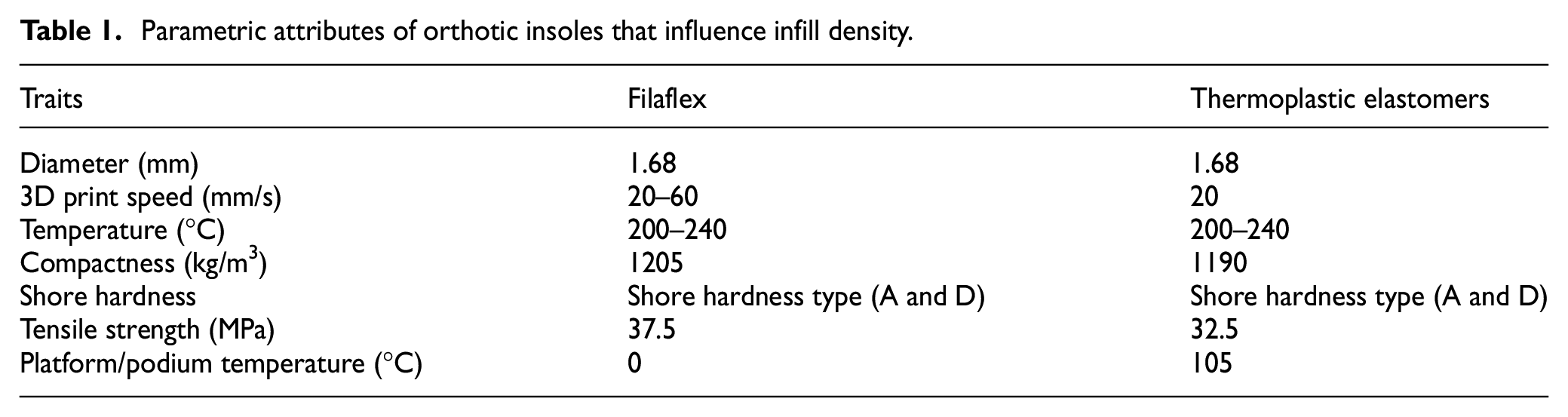
Filaflex and thermo-softening viscoelastic polymer (i.e. Ninjaflex) is a few sorts of material that comprise elastic. These materials are adaptable in devise or plan, superior and alleviate of handling that has prompted creators to progressively turn as material of decision. Table 1 demonstrates the Filaflex strand and Ninjaflex traits/possessions of the parameter. Initially, the materials used for this study are Filaflex strand and Ninjaflex fiber as shown in Figure 4. Though, the form/kind of infill replica utilized is hexagonal, and the percentage infill such as 10%, 20%, 30%, 40%, half, 60%, 70%, 80%, 90%, and 100%.
Parametric attributes of orthotic insoles that influence infill density.
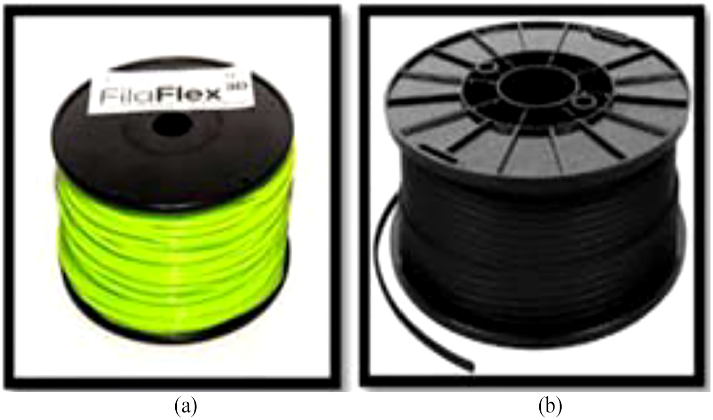
(a) Filaflex and (b) thermo-softening viscoelastic polymer, that is, Ninjaflex.
Also, another parameter such as infill density is considered to compare the hardness, tensile strength, and flexural strength of the test piece produced. Two different TPUs are compared, and conclusions are drawn by using prints drawn on the basis of Flash Forge 3D printers.
The Flash Forge 3D printer is a most moderate, simplest, quickest apparatus for manufacturing proficient quality models. The Flash Forge desktop 3D printer is compatible with working frameworks such as Linux, Mac, and Windows. MakerWare desktop 3D printer programming is utilized as a correspondence medium among PC and Flash Forge. MakerWare is free programming that incorporates everything, including an exceptionally quick device and a fresh out of the plastic new easy to understand interface. Standard test examples were ready, depending on ISO 37 for tensile test.1,5,6
Tensile test method
Tensile strength is the most essential and normal materials testing technique. It is given information based on a definitive quality, modulus, stretching, and durability, and it also yields quality. This test is carried out at both low and high temperature, so as to research whether there is any distinction in the information increased because of this variable. The temperatures that are generally used are 40°C and furthermore 200°C for low and high temperatures separately. Usual testing for elastic or elastomeric materials is ISO 37, which further depicts a strategy for the assurance of the malleable stress–strain possessions of vulcanized and thermo-softening rubbers. The estimation of stress–strain at design yield limit pertains only to some thermo-softening elastomeric materials.
Tensile test is performed by Instron machine under ISO 5893 (Shimadzu, DSES-1000 extensometer with load capacity of 1 kN, Japan). The machine is equipped for playing out the test at pace of a cross-thwart of 100, 200, and 500 mm/min. By these methods for elastomer testing ability and secluded manufactured, it will be help to discover the testing arrangements that are accurate. The tensile test samples are shown in Figure 5.
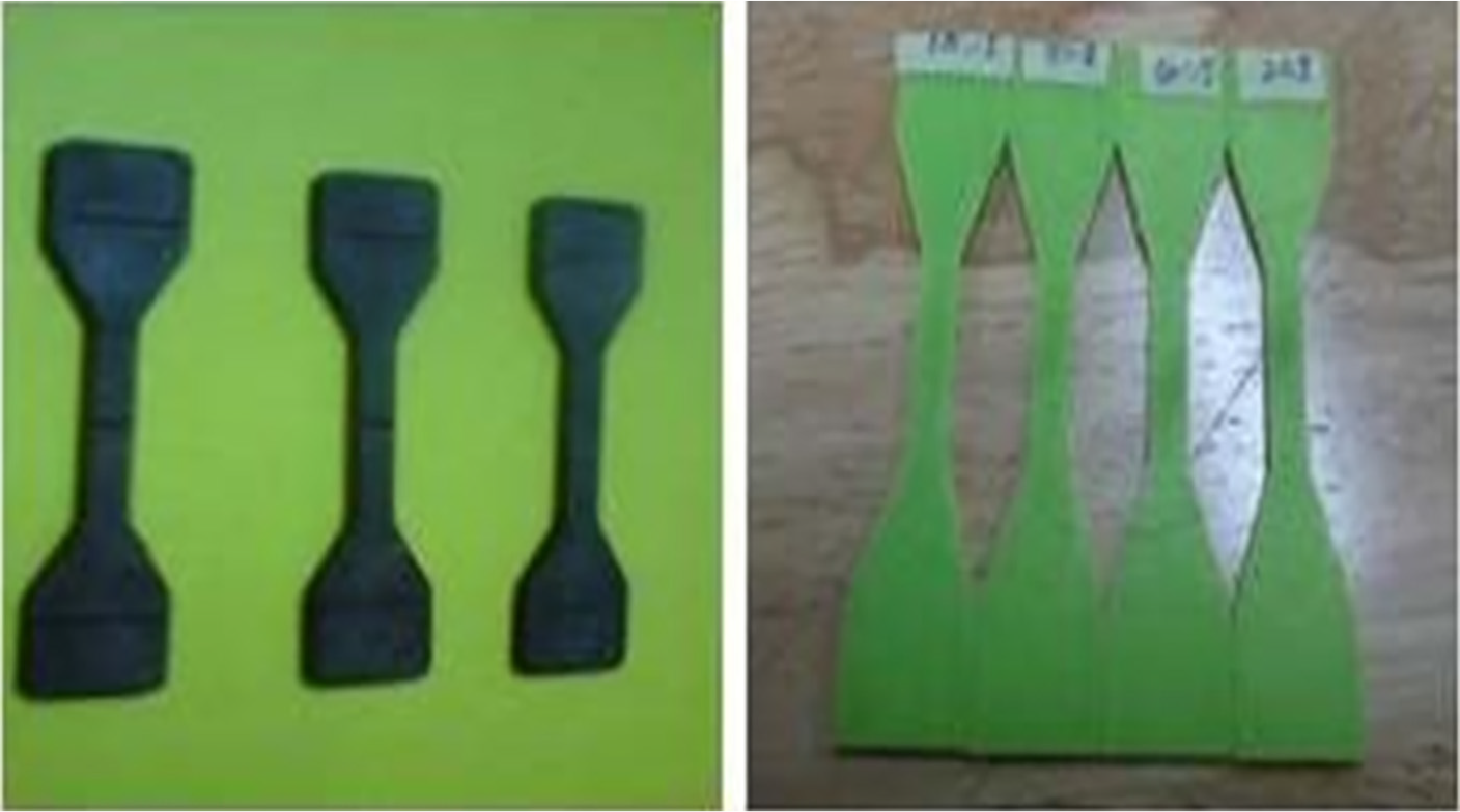
Tensile test specimens of elastomer inserts or insoles for an orthopedic application.
Hardness test method
Durometer hardness tester (Elcometer-3120, Shore Durometer, USA) is used to recognize the general hardness of delicate materials, generally polymer or elastomer. The estimations are taken by penetrating a foreordained needle-like into the stuff texture under demonstrated conditions of time and strength. The hardness parameter is routinely used to decide the particular hardness of elastomers or as a quality control to quantify on a set of materials. The hardness test samples are shown in Figure 6.
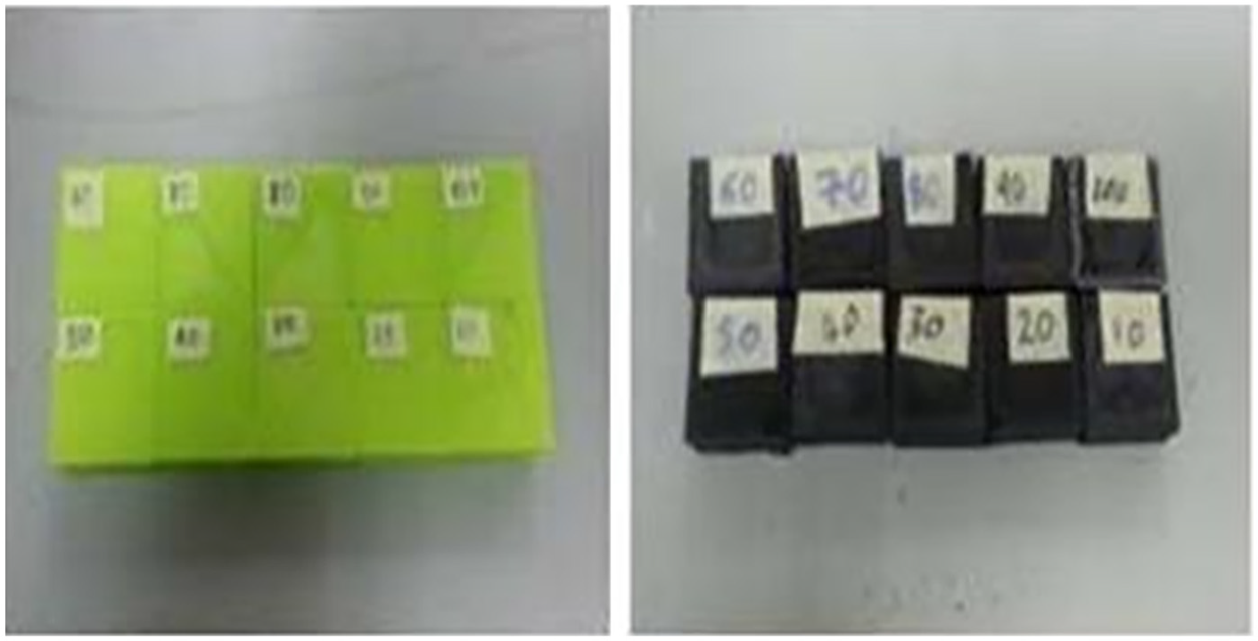
Hardness test specimens of elastomer inserts or insoles for an orthopedic application.
The hardness numbers are taken from an extent of shore A and shore D in a likely manner, with the shore A, gamut extent being used for malleable materials and the shore D measure is used for rigid or tough materials. Durometer indenter into texture stuff gives the estimation of the hardness under ASTM D2240.
Flexural strength test method
Testing of twisting or flexural properties of these fabric strands is very regular to discover its conduct. The standard flexural is either three- of four-point types of bending test which is used to test unbending and semi-inflexible thermoplastic elastic materials. The method utilized for this examination is flexural with three-point twisting. The bending test specimens are shown in Figure 7. As such, the fracture strength can be characterized as the capacity of a material to withstand twisting force that applied right angle to its longitudinal pivot. Three-point bending test is performed by Instron machine with deflection measuring system under ISO 178 (Shimadzu, AGS-X model of load capacity 1 kN, Japan).
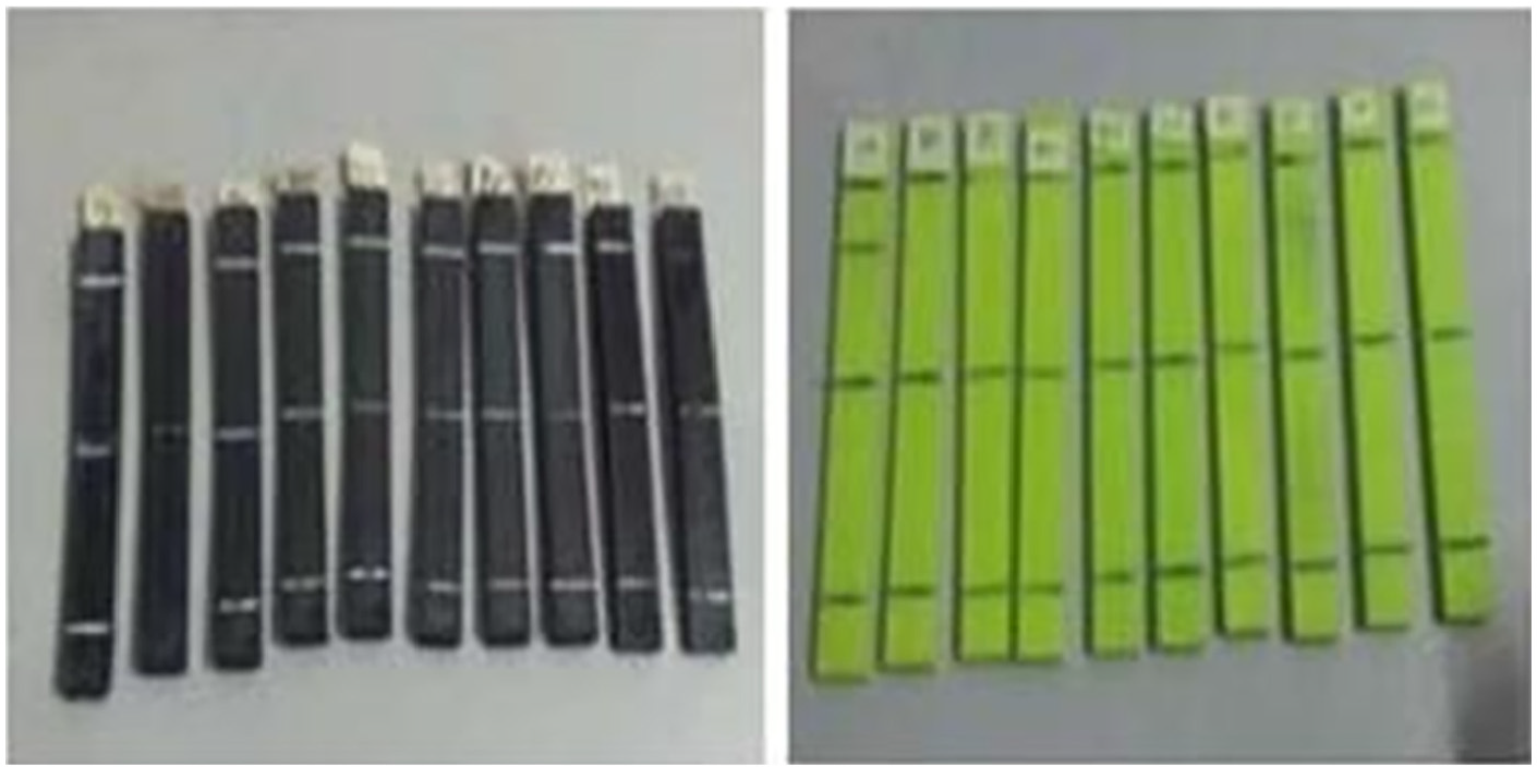
Three-point bending test specimens of elastomer inserts or insoles for an orthopedic application.
Results and discussion
Table 2 illustrates the hardness against percentage rate of infill for Filaflex and Ninjaflex fabric strands. Subsequent to get some analysis of the hardness fabric stuff like Plasterzote, P-Light, and Nora which are the materials utilized at medical store as material of orthotic insoles, the outcome is listed in Table 3, where the information is closer to the Filaflex hardness. From that, Filaflex is the most appropriate and compelling material, as foot orthotic insoles depend on the hardness test results.
Hardness against percentage rate of infill for Filaflex and Ninjaflex.

Hardness of Plasterzote, P-lite, and Nora materials.
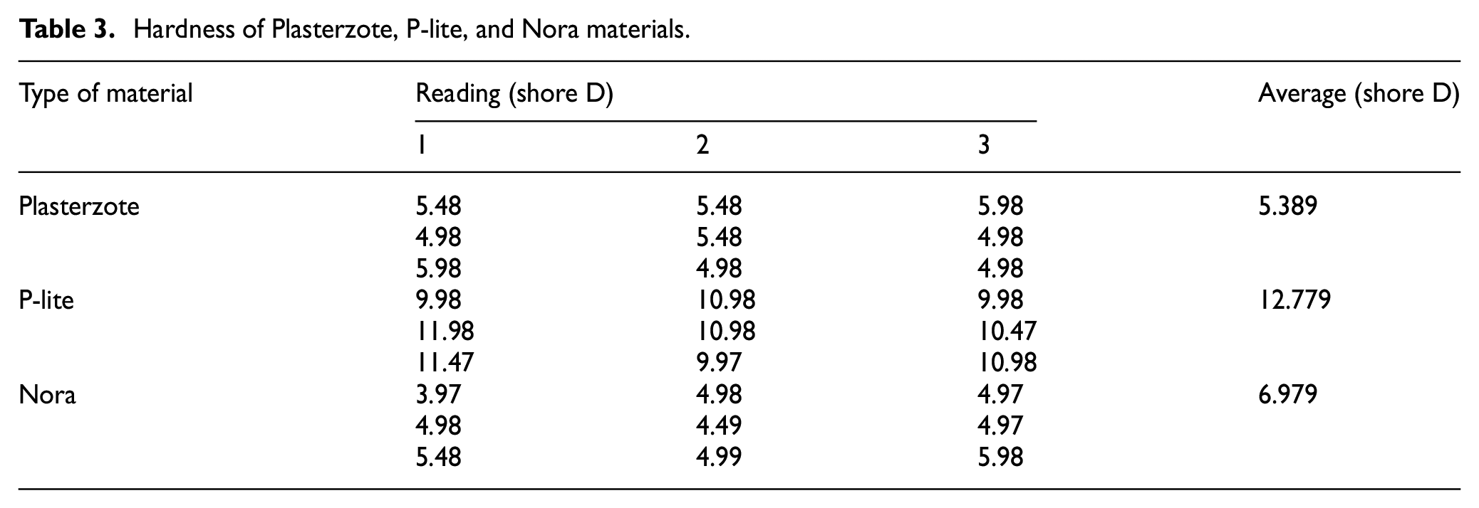
The mean demonstrated that the hardness of Ninjaflex is vastly diverse as contrasted with Filaflex in light of the fact that Filaflex fabric stuff is influenced by a delicate structure. The graphical diagram demonstrates hardness against percentage rate of infill for Filaflex and Ninjaflex, as shown in Figure 8. At 100% plight condition, where the two samples were in concavity structure, the perusing of Filaflex tranquil stumpy at 30.3 shore D contrasted with the 55.7 shore D of Ninjaflex hardness. The lighter the hardness esteem, the more efficient the fabric stuff as orthotic foot inserts.
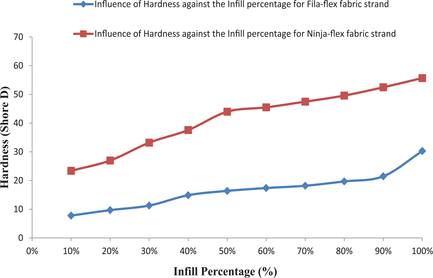
Variation of hardness with percentage of infill for Filaflex and Ninjaflex.
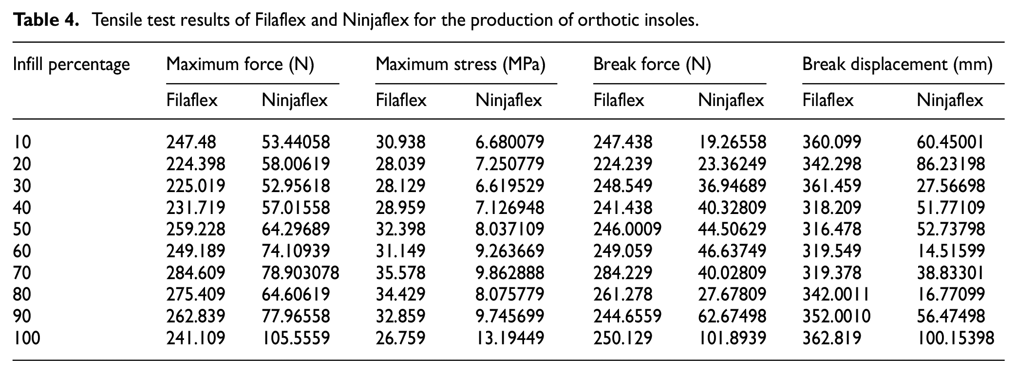
These samples are printed using the Flash Forge 3D printer following the ISO 5893 and ISO 37. The results from this research made it clear that Filaflex is far better than Ninjaflex for insole production. The results are given in Table 4. At 70% infill design replica, the most extreme strength for the Filaflex recorded is 284.609 N. At 100% fill-up, the maximum strength of Ninjaflex reported is 105.5559 N. The graphical diagram, as illustrated in Figure 9, demonstrates the break disarticulation (mm), against the percentage level of infill for the two fabric stuffs, Filaflex and Ninjaflex. From here, it may be observed that the Filaflex material can be prolonged and resists high strength before it fails, and it may be called as a very flexible/resilient fabric stuff.
Tensile test results of Filaflex and Ninjaflex for the production of orthotic insoles.
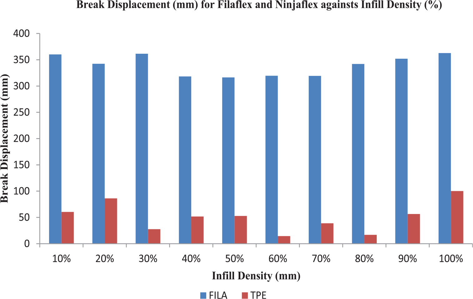
Break disarticulation (mm) against the percentage level of infill for the two fabric stuffs, Filaflex and Ninjaflex.
The graphical chart demonstrates the disparity among Filaflex and Ninjaflex for maximum strength (N) against the percentage level of infill compactness (%), as illustrated in Figure 10. In view of this diagram, the most extreme strength necessitated by Filaflex is higher contrasted with the strength entailed by every percentage rate infill of Ninjaflex.
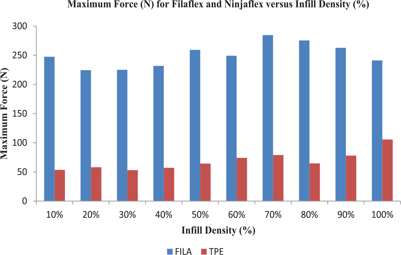
Maximum strength (N) against the percentage level of infill compactness (%) for the two fabric stuffs, Filaflex and Ninjaflex.
While the Ninjaflex material changed its flexibility possessions in the wake of additive manufacturing, it implies, subsequent to warming, that its resilient assets had been altered because of warm and also may root by layer binding not well. At 100% rate infill of the rupture dislodgment, the most astounding information recorded for the two stuff fabric strands are 362.819 mm for Filaflex and 100.15398 mm for Ninjaflex. The break strength of Ninjaflex is still low contrasted with percentage level of Filaflex infill design replicas.
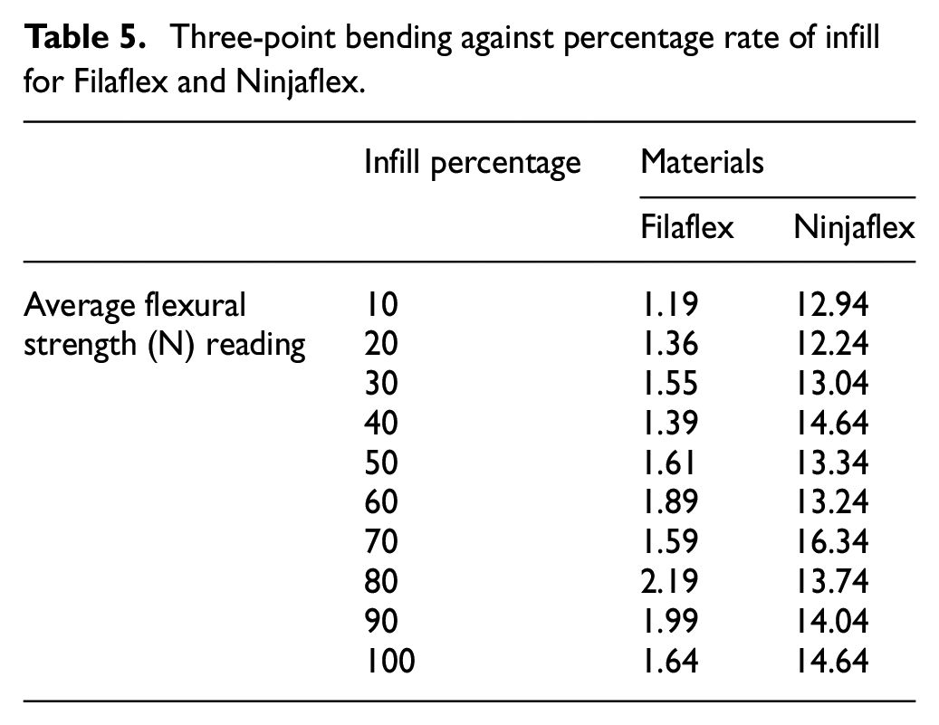
Table 5 illustrates flexural strength against percentage rate of infill for Filaflex and Ninjaflex fabric strands. At 70% of Ninjaflex, infill replica illustrates that the most elevated twisting force with 16.34 N, as contrasted with Filaflex at 80% with 2.19 N, had the most noteworthy fracture force. Be that as it may, the lower modulus of rupture of the material, one of the parameters to be considered, is the abnormal state of elasticity or flexibility.
Three-point bending against percentage rate of infill for Filaflex and Ninjaflex.
The graphical representation, as shown in Figure 11, demonstrates the flexural strength (N) for Filaflex and Ninjaflex against Infill percentage thickness (%). At 70% of Ninjaflex, infill replica illustrates that the most elevated twisting force with 16.34 N, as contrasted with Filaflex at 80% with 2.19 N, had the most noteworthy fracture force. Be that as it may, the lower modulus of rupture of the material, one of the parameters to be considered, is the abnormal state of elasticity or flexibility. The fracture or twisting force acquired is distinctive as appeared in the table underneath the chart; this demonstrates the supremacy of transverse rupture the subsequent replicas differ as indicated by the sort of charge and is likewise reliant on the kind of material formed. In view of the outcomes, the perusing of Ninjaflex is higher when contrasted with perusing of Filaflex. The subsequent structure is somewhat harder Ninjaflex analyzed Filaflex structure and versatile elastic low levels in light of the fact that the material shows the percentage of high readings in the charging replicas. In spite of the fact that, the both fabric strands are flexible, elastic and won’t break when exposed to twisting force over which supremacy is very essential to distinguish the capability of a material for most extreme adaptability at a point before the material is completely adaptable/flexible. The lower the bending strength of the material, the better the formation of liner away; one of the parameters to be measured is the elevated echelon of elasticity as well as flexibility. At the point when the degree of a substance demonstrates a high flexible/elastic is driven by the delicate nature of the fabric strand structure.
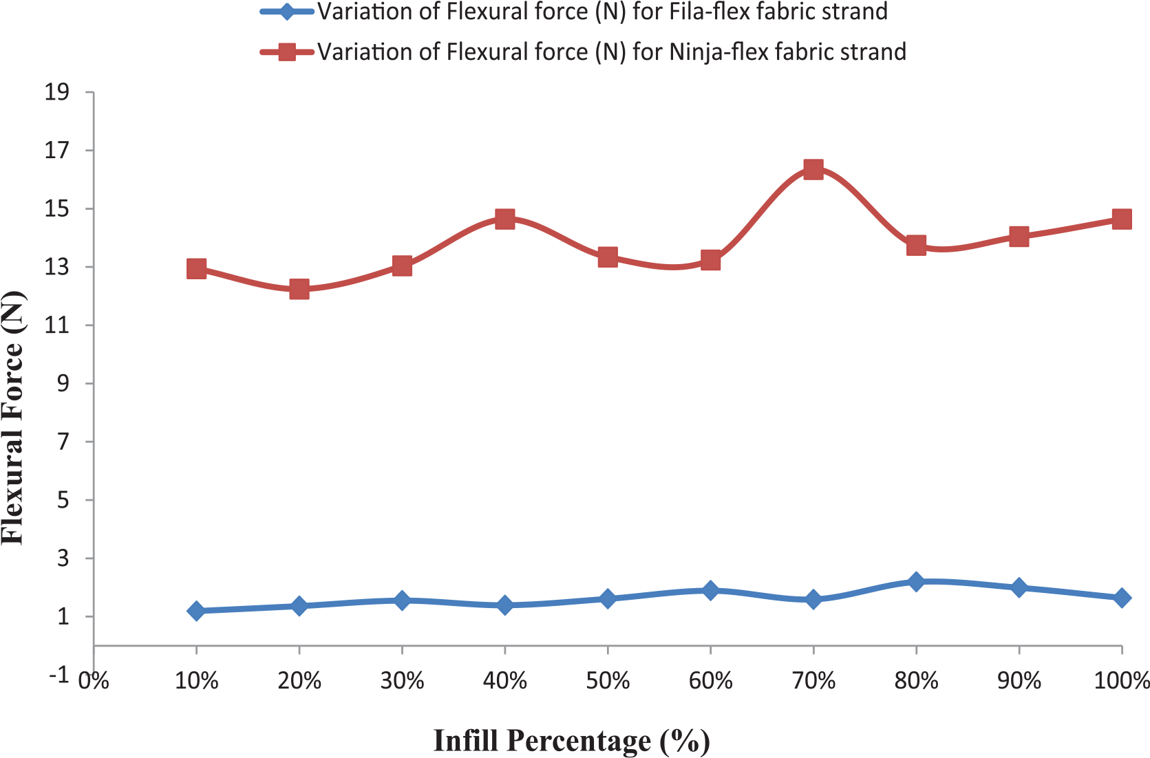
Influence of bending force with percentage of infill for Filaflex and Ninjaflex.
Conclusion
Thermo-softening viscoelastic polymer, explicitly Filaflex and Ninjaflex, has been printed through FDM by utilizing Flash Forge 3D printers to evaluate the mechanical properties of specimens with alterations of the percentage rate fill-up design replicas. The results are compared on the basis of hardness test, flexural/bending test, and tensile test. The following conclusions are drawn:
Filaflex is superior rather than Ninjaflex where 284.609 N for most utmost force with 70% of fill-up of rigidity of Filaflex.
Modulus of rupture of Filaflex infill prototype replica attained 2.19 N for bending force with 80% of infill percentage of fabric strands.
The most minimal hardness (shore D) of Filaflex obtained 7.78, which shows preeminent edifice hardness of orthosis foot inserts/insoles.
Effects of many parameters have been studied that affected the properties of orthotic insoles, but the main affecting factor is the infill density.
It has been concluded that no study was found peculiar in the specific area of insole, and investigation may be carried out for tear strength.
Footnotes
Acknowledgements
The authors wish to acknowledge the Department of Research, Innovation and Consultancy, I.K. Gujral Punjab Technical University, Kapurthala, Punjab, India. This work was completed in part with resources provided by CSIR-Central Leather Research Institute, RCED, laboratory. The authors appreciatively acknowledge the support of CSIR-Central Leather Research Institute, RCED, laboratory for providing opportunity to conduct this research task.
Declaration of conflicting interests
The author(s) declared no potential conflicts of interest with respect to the research, authorship, and/or publication of this article.
Ethical approval
This article does not contain any studies with human participants or animals performed by the authors.
Funding
The author(s) received no financial support for the research, authorship, and/or publication of this article.