
Abstract
In this paper, the vibration characteristics of the designed hybrid truss-type movable heavy-load pouring robot (pouring robot) and the pose control of the parallel working arm are studied. The dynamic-static method is used to simplify the truss and parallel working arm of the pouring robot into a forced vibration system composed of spring, damping, and mass body, based on this the 9-degree-of-freedom vibration equation of the pouring robot is established, the analysis of the amplitude–frequency characteristics shows that the four input vibrations of the pavement have basically the same influence on the ladle, which will cause the ladle to resonate. Kane’s method is used to establish the lower mobility dynamic equation of the parallel working arm, the Jacobian matrix of force-driven and torque-driven coupling are given. Based on the vibration characteristics of the pouring robot and the dynamic model of the parallel working arm, an adaptive sliding mode control method with radial basis function neural network compensator and Newton–Euler iterative estimator are proposed to realize the pose control of the ladle, the Lyapunov theorem proves the stability of the control method, the simulation results show that adaptive sliding mode control has better control performance, faster response speed, higher convergence accuracy, and better robustness than traditional sliding mode control algorithm. The paper provides a reference and research basis for the suppression of ladle vibration when the pouring robot is transferred, which is affected by the road roughness.
Introduction
Pouring is the process of injecting molten metal from the ladle into the mold cavity. The common pouring methods are bottom injection type, pouring type, pneumatic type, and so on. 1 In this paper, a hybrid truss-type movable heavy-loading pouring robot is designed using the characteristics of strong load capacity of parallel mechanism, which can realize the adaptability and flexibility requirements of casting equipment in the production of multi-variety small batch products. 2
The road roughness causes the vibration of the pouring robot, and the severe vibration will cause the spilling of the molten metal. The pouring robot is approximated as the vehicle suspension system. Litak et al., 3 Akçay and Türkay, 4 and Shaohua and Jianying 5 used the Melnikov, Mean, and Galerkin method to study the chaotic vibration of the single-degree-of-freedom vehicle suspension model, the dynamic response of the random road surface, and the nonlinear dynamics of the vehicle. Yang et al. 6 and Cai et al. 7 studied the road excitation of a 2-degree-of-freedom (2-DOF) vehicle model and the nonlinear dynamics of the suspension. Zhu and Ishitobi 8 and Gao et al. 9 studied the spectrum and nonlinear dynamics of a 4-DOF half-vehicle suspension model excited by rough road surface. Zhang et al. 10 and Wang et al. 11 established a 7-DOF vehicle vibration model. This research is based on the standard vehicle model, discussing its modeling method, as well as the evaluation index of the road body excitation on the car body and the carrier; for the non-standard vehicle, usually containing complex additional components, the vehicle will have higher DOF and complex vibration state, and there are few modeling and simplification methods in this aspect.
The classical methods for dynamics modeling of parallel mechanisms include Newton–Euler equation, Lagrangian equation, Gaussian minimum restraint principle method, and Kane equation. 12 For the control of the trajectory and pose of the parallel mechanism, the proportional derivative/proportional integral derivative (PD/PID) control method is generally adopted, but the PD/PID cannot track the expected trajectory and pose of high dynamic motion of nonlinear dynamic systems. 13 Sliding mode control (SMC) is a robust control scheme with good ability to overcome nonlinear, time-varying parameters, disturbances, and uncertainties. Ouyang et al. 14 proposed a PD-SMC controller for robot trajectory tracking control, and discussed some adjustment rules of the controller through simulation. Soltanpour et al. 15 and Navabi et al. 16 combine SMC with fuzzy systems to improve controller performance with uncertain structural and non-structural parameters. Fei and colleagues17,18 proposed a radial basis function neural network (RBFNN) and double closed-loop recurrent neural network based on adaptive sliding mode controller for a class of nonlinear dynamic systems, that is, all states are measurable and the input gain matrix is unchanged. The improved SMC is used in the above literature and combined with other excellent algorithms to control the pose and trajectory of the parallel mechanism, and achieve good control effects. The real-time control depends on the end attitude sensor, but in the vibration suppression, the real-time acquisition of the end pose is very demanding, and an excellent sensor is required.
In this paper, the dynamic–static method is used to simplify the vibration of the ladle into a forced vibration, and then establish the 9-DOF vibration equation of the pouring robot; Kane’s method is used to establish the dynamic equation of the parallel working arm, the form of the Jacobian matrix of the rotational drive and linear drive coupling, and the dynamic equation of the force and torque are given; the ASMC with RBFNN compensator and Newton–Euler estimator is proposed, the method estimates the state variables through the changes of the driving, thereby realizing the real-time control of the pose, and suppresses the influence of road roughness during the transition of the ladle.
Vibration model of parallel pouring robot
Vibration model of the whole machine
Figure 1 is a schematic diagram of the structure of a hybrid truss-type movable pouring robot. 19 The design dimensions of the whole machine are 2150 mm × 1200 mm × 2000 mm, the maximum load is 60 kg, and the design working space of the parallel working arm is 100 mm × 50 mm × 400 mm.
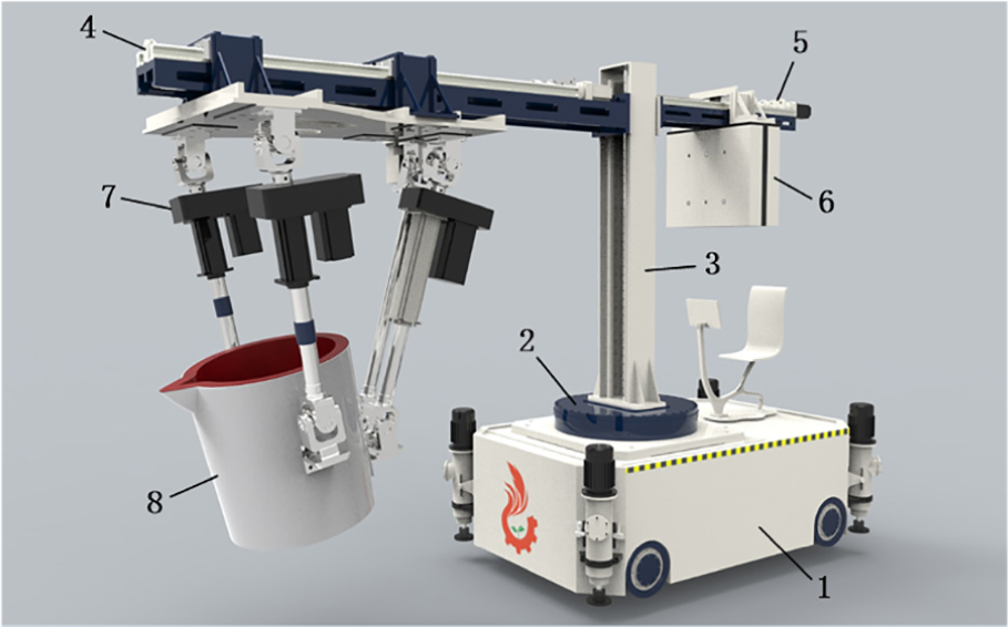
Hybrid truss-type movable heavy-load pouring robot.
To study the dynamic characteristics of the pouring robot under the excitation of rough road surface, the pouring-vehicle–ground interaction can be effectively and reasonably predicted, and the movement of the parallel working arm can be realized to avoid the splashing of molten metal in the ladle due to severe vibration. This paper assumes that the vibration behavior of the casting robot conforms to linear rules and is simplified to the body, unsprung mass, spring, suspension, and tire composition, and a 9-DOF vibration model as shown in Figure 2 is established. Figure 3 is a simplified model of the truss of the pouring robot (composed of 4–8 in Figure 1). According to the dynamic–static method 20 in the material mechanics, the truss is simplified into the forced vibration of the 2-DOF elastic system.
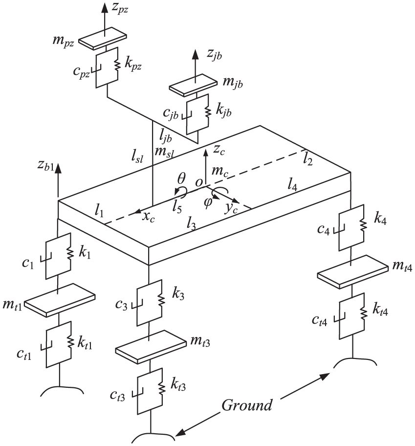
A 9-DOF vibration model of pouring robot.
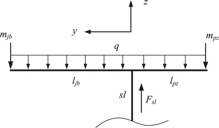
Simplified model of the truss.
In Figure 3, the counterweight and ladle are simplified to the mass bodies mjb and mpz applied to the ends of the truss. The truss is approximately a homogeneous rod with a unit mass of q. The lengths from the support beam (sl) to the ends the truss are ljb and lpz, respectively, and the gravitational acceleration is g. Then, based on the superposition principle of material deformation, the static displacement of the ladle is
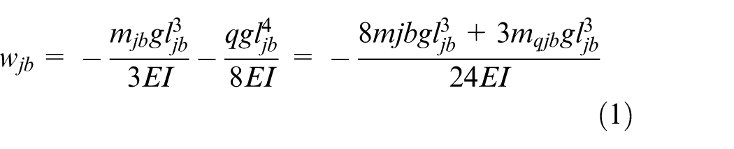
In equation (1), E and I are the elastic modulus and the moment of inertia, respectively. Obviously, the quality and position of the ladle play a major role in the vibration of the ladle. So, rewrite equation (1)
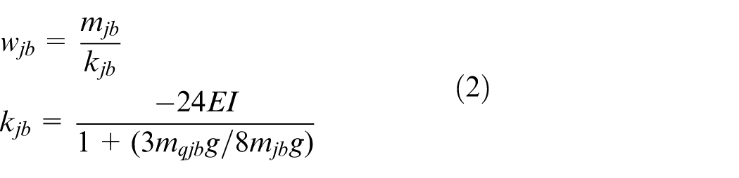
where kjb is the spring constant, then the vibration equation of the ladle is

In equation (3), mqjb = mqljb, cjb is damping, which can be obtained by experimental or theoretical formula, and Fd is external force. The same method can be used to obtain the vibration equation of the counterweight.
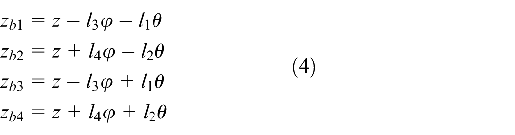
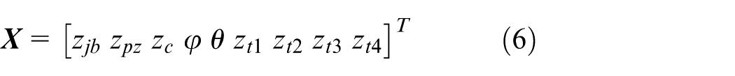
In Figure 2, zjb and zpz are the vertical displacements of the ladle and the counterweight, respectively; zc is the vertical displacement of the centroid of the moving platform of the pouring robot; φ is the pitch angle of the moving platform; θ is the roll angle of the moving platform; l1 is half of the front axle track; l2 is half of the rear axle track; l3 is the distance from the center of mass to the front axle track; l4 is the distance from the center of mass to the rear axle track; mc is the mass of the mobile platform located at the origin of the coordinates o; and Jyc and Jxc are the pitching moments of inertia of the mobile platform. zbi (i = 1–4) is the vertical displacement of the support point; ci and ki are the damping and stiffness of the suspension, respectively; mti is the total mass of the suspension and the tire; cti and kti are the damping and stiffness of the tire, respectively; qi is the vertical displacement from the ground. msl is the mass of the lifting device, the center of mass is located in the middle of the lifting device, the length is lsl, l5 is the distance from the lifting device to the center of mass of the mobile platform, and the lifting device is fixedly connected with the mobile platform.
Assuming that φ and θ are small, the vertical displacement relationship between the four support points of the vehicle body is
The 9-DOF differential vibration equation of the pouring robot is established by the isolation method. The matrix form can be written as

In equation (5)

In equation (8), Jysl and Jxsl are the moments of inertia of the lifting device in the yc and xc directions.
Numerical analysis of vibration of parallel pouring robot
To analyze the influence of the road roughness on the vibration characteristics of the ladle, we can obtain the state space equation of the pouring robot from equation (5)
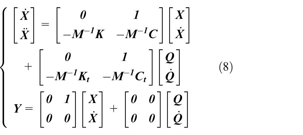
In equation (13),
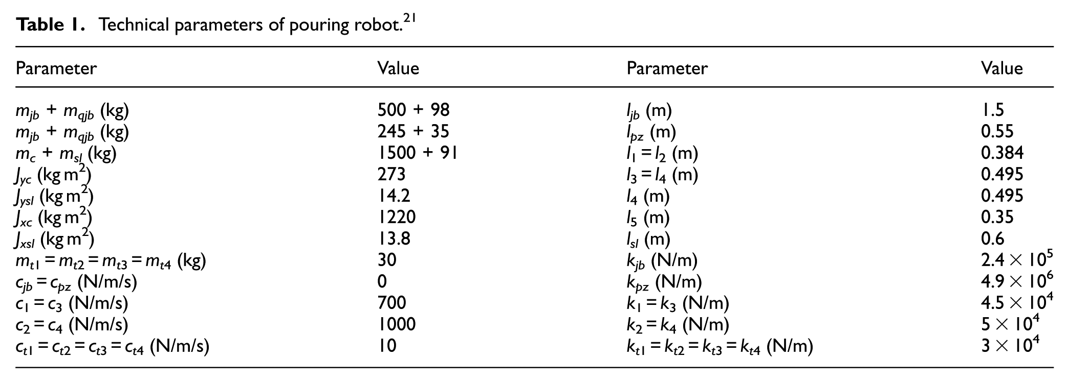
Technical parameters of pouring robot. 21
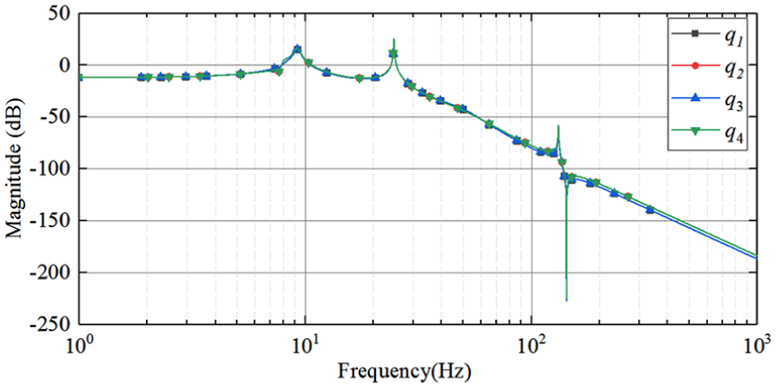
The amplitude and frequency characteristics of the ladle.
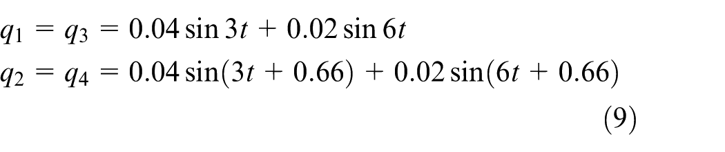
In Figure 5, taking a type of aperiodic deceleration band input model as an example (equation (9)), it can be seen that the vibration of the ladle is compound vibration, and the acceleration and displacement changes are irregular, the maximum displacement and acceleration are 0.15 m and 10 m/s 2 , respectively, and the amplitude fluctuates sharply. When the pouring robot is working on this kind of road surface, the vibration of the ladle will inevitably cause the vibration of the molten metal, in severe cases, it will cause a spill accident. Therefore, the active movement of the parallel working arm is required to offset or reduce the vibration of the ladle.
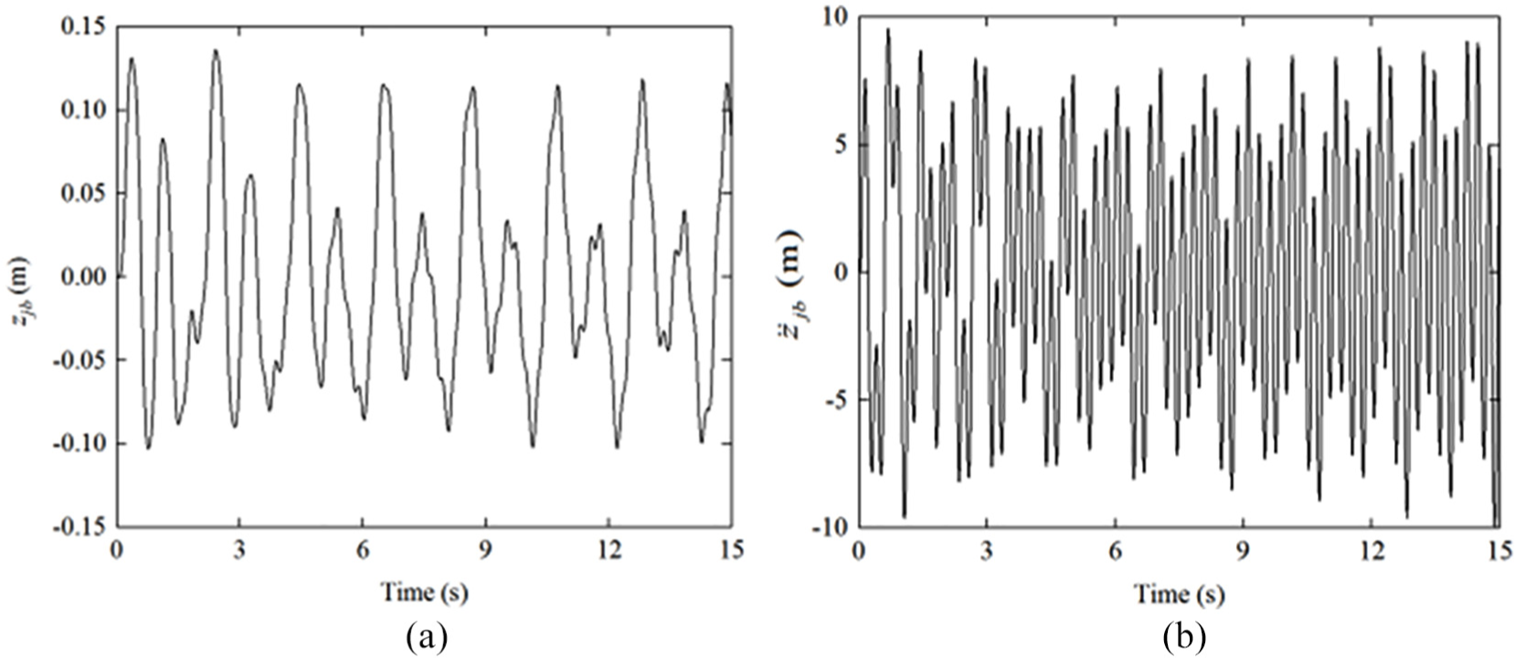
Vibration of the ladle: (a) vibration displacement of the ladle and (b) vibration acceleration of the ladle.
Dynamic modeling of parallel working arm
To realize the active motion of the pouring robot to reduce the vibration of the ladle, the dynamic equation of the parallel working arm must be established. In this paper, the Kane method is used to establish the dynamic equation of the parallel working arm.
Figure 6 is a simplified diagram of the parallel working arm simplified to a 4-UPU (U stands for universal joint and P stands for moving pair) parallel mechanism.
19
ABCD stands for fixed platform, abcd stands for moving platform, γ is the inclination of the ladle, and C(c) is located on the extension of the midpoint of AB(ab). m, n, k, M, N, and K represent the relevant structural dimensions of the fixed platform and the moving platform, d1, d2, d3, and d4 represent the length of the four branches. The UPU can be decomposed into an RRPRR structure.
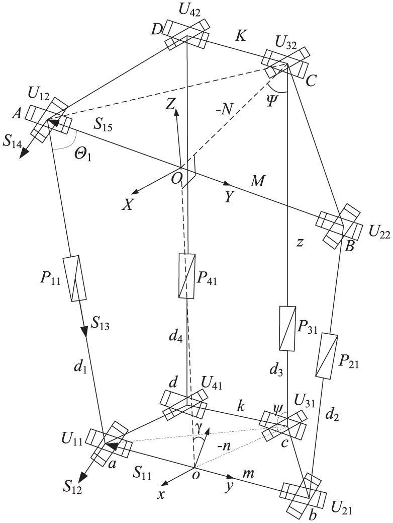
A 4-UPU parallel mechanism.
The velocity, acceleration, and partial velocity of the centroid of each component of the branch
Taking branch 1 as an example, the change of
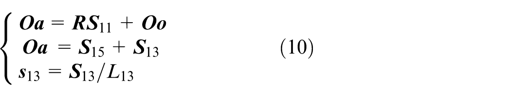
In equation (10),
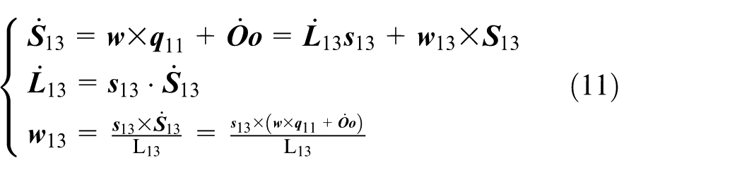
where
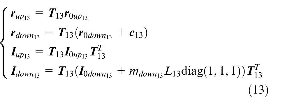
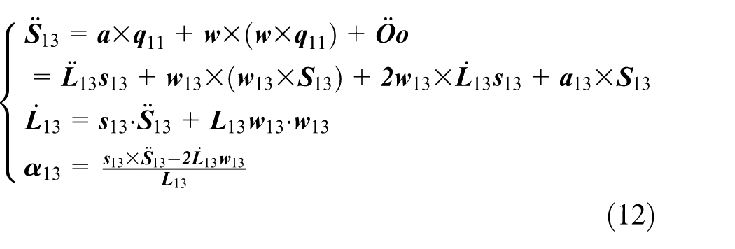
In equation (13),
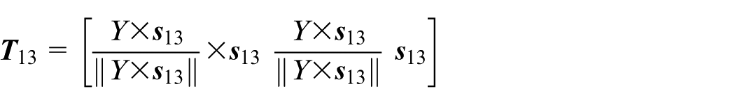
According to the simultaneous equations (11)–(13), the velocity and acceleration of the centroid of the upper and lower parts of the chian 1 can be obtained
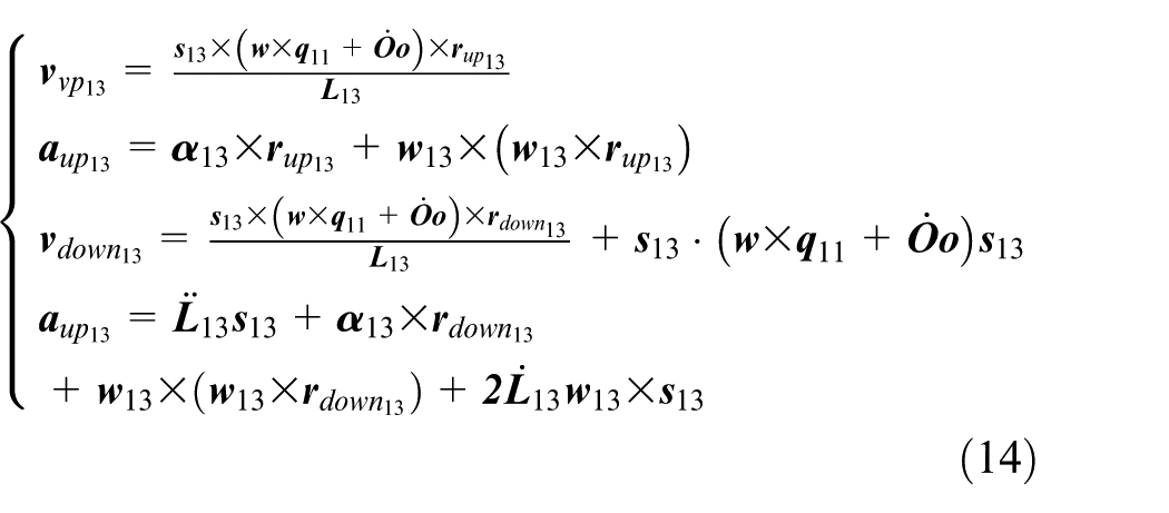
The 4-UPU mechanism designed in this paper is a 3-translational and 1-rotation parallel mechanism, and the generalized angular velocity
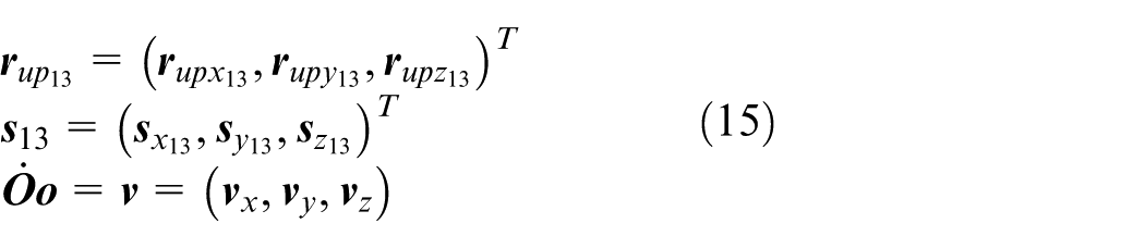
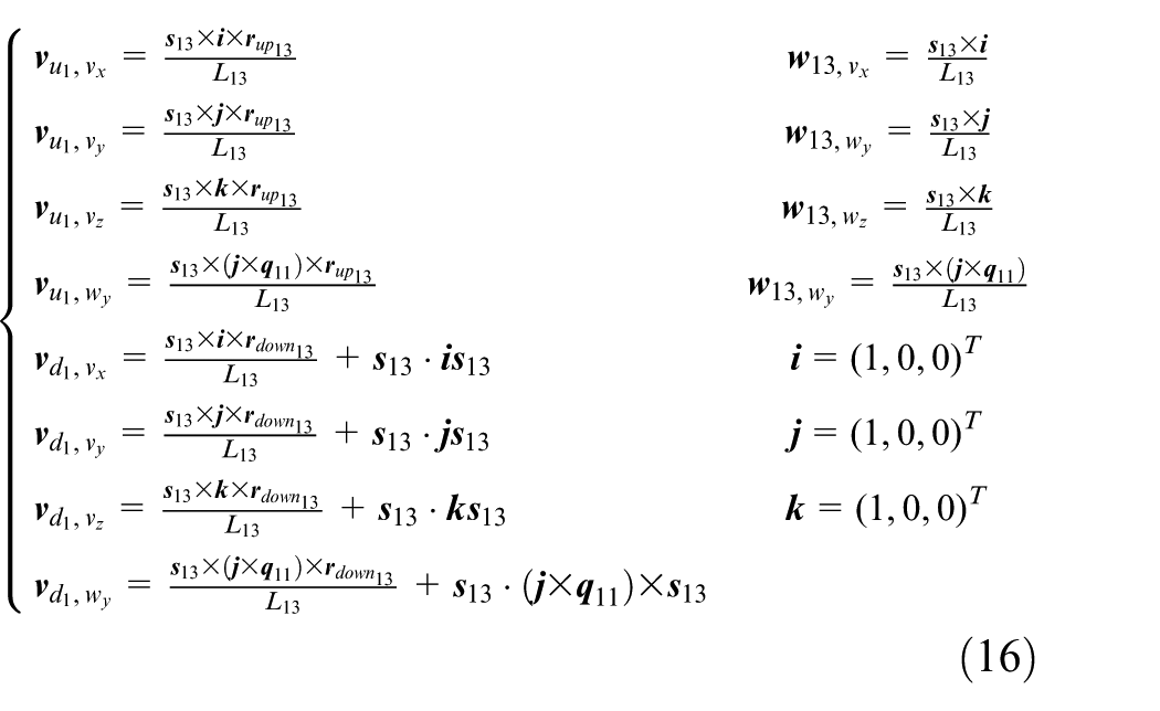
Equation (15) is brought into 14 for partial expansion and is organized into equations for vx, vy, vz, and wy. Thus, the derivation rule can be used to obtain the partial velocity of the upper and lower parts of the branch 1 relative to the generalized velocity (
The velocity, acceleration, and partial velocity of the centroid of each component of the moving platform
The moving coordinate of the moving platform is at the center of mass, and the velocity and acceleration of the moving platform are:
Dynamic equations of parallel working arm
In Figure 6, the rotating pair
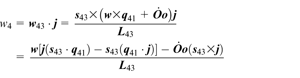
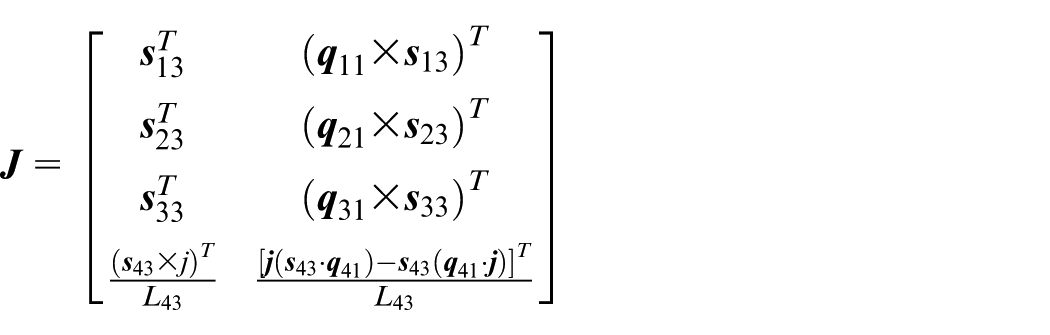
Then, the Jacobian of the parallel working arm is
The forces on the parallel working arm include the driving force of the branch
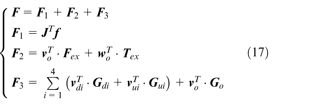
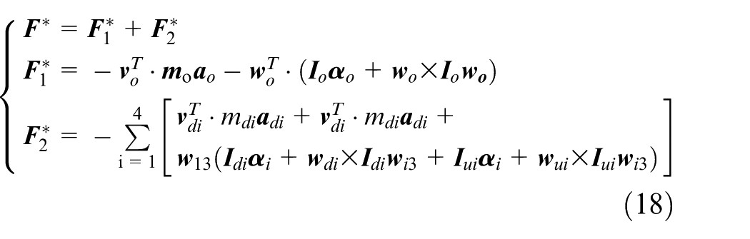
In equations (17) and (18),
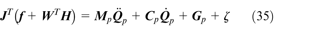
In summary, the dynamic equation of parallel parallel working arm is as follows

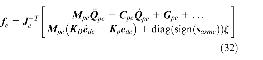
Further, the driving force and driving moment of each branch chain can be obtained by equation (19) as follows
Numerical analysis of dynamics of parallel working arm
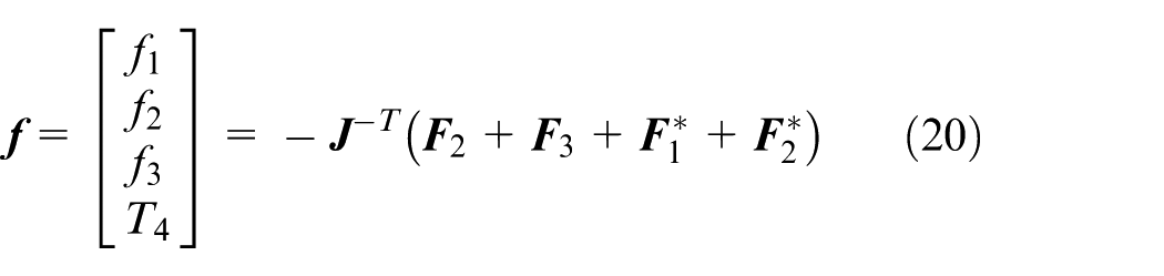
Equations (10)–(20) are compiled into MATLAB and the structural parameters are shown in Table 2. The arc track in the XZ plane is taken as an example. The center point
Structural parameters of parallel working arm.
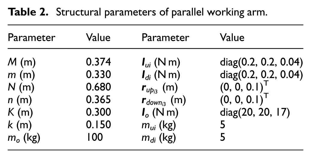
Driving force changes with time in a circular path.
Figure 7 shows that due to the interaction between different components, the driving force/torque is increased or decreased. The force and moment at the start and end points after one cycle of motion are equal, reflecting the dynamic characteristics of the mechanism and proving the correctness of the Kane algorithm.
Control scheme design
When discussing ladle control, there is a problem of rigid–liquid coupling, but combined with the previous research work23,24,25 and the actual working environment, the liquid is not sensitive to the vertical displacement, and the road input does not not change sharply, the ladle also has a sloshing margin. Therefore, to facilitate the control study, the pouring liquid is considered as the quality of the ladle.
For equation (19), it can be organized into a dynamic standard form
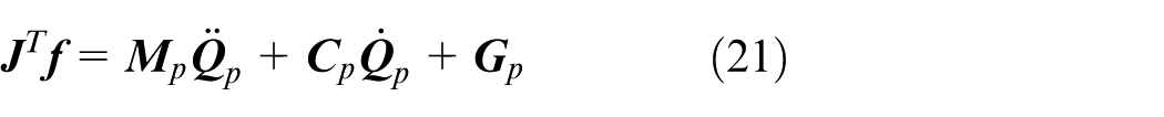
In equation (21),
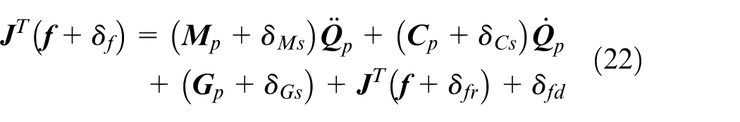
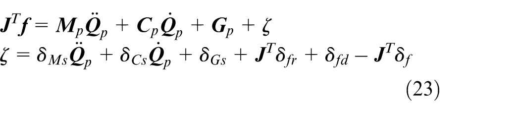
In equation (22),
Standard SMC
The author found that the PD control has a certain effect on the fixed-point control of the parallel working arm, so the standard sliding surface is selected as
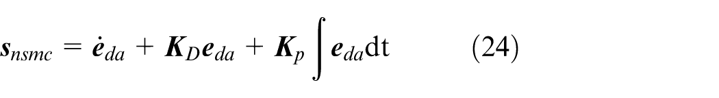
where
Proof 1
The Lyapunov function of the standard sliding surface can be designed as
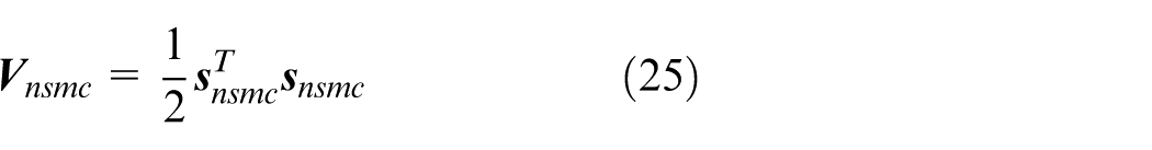
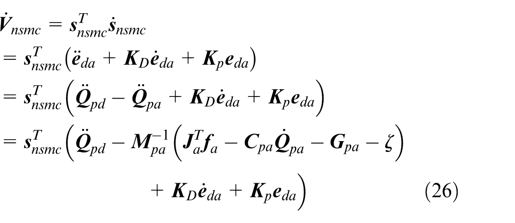
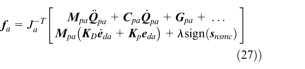
Bringing equation (27) into equation (26), we get
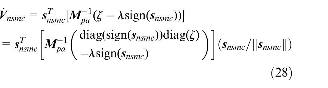
(*)*d and (*)*a represent the parameters of the desired pose and the actual pose. In equation (28), since
Assumption 1
The total uncertainty parameter
Proof by equation (32) and Assumption 1

Therefore, the control law given by equations (24)–(29) can achieve the control target
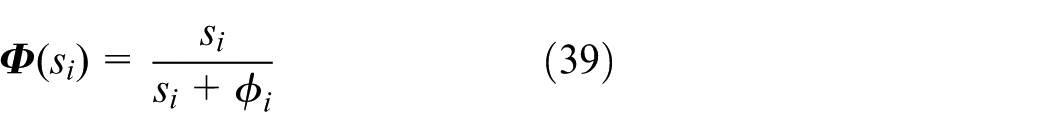
But, there are still several problems with the standard SMC. First, the real
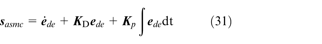
ASMC
Since the displacement and rotation of the driving in the parallel working arm are independent variables, the change of the driving
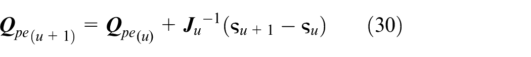
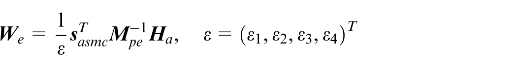
where
(*)*e indicates the estimated pose parameter,

Because the RBFNN has a simple structure and good global convergence, it is often used in approximation problems, and the response speed is fast. Therefore, this paper intends to use RBFNN as compensator for uncertain parameters. The RBFNN architecture uses the simplest input layer
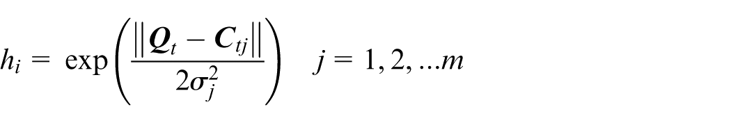
Then, the output of the RBFNN is written as
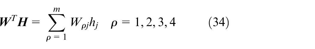
where Wρj is the connection weight, and equation (22) is rewritten as
Proof 2
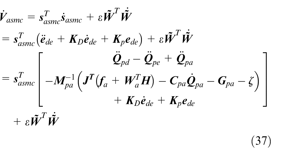
The Lyapunov function of the adaptive sliding surface can be designed as
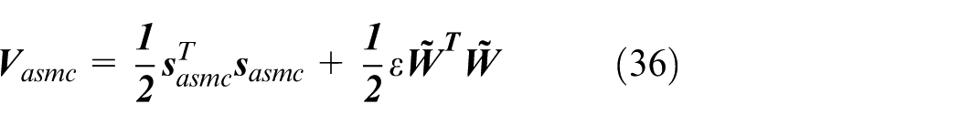
where
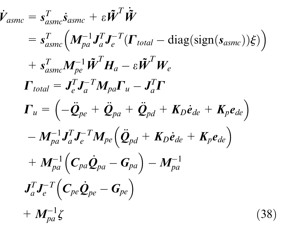
Assumption 2
Under the condition of friction, uncertain dynamics model, environmental disturbance and driving fault, the total uncertainty parameter

Assumption 3
Adaptive law can choose
From Assumptions 1 and 2, equation (37) can be obtained
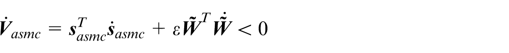
Proof 2 shows that the ASMC of the design can achieve
where
Numerical analysis of control schemes
To verify the proposed ASMC algorithm, the algorithm is compiled into MATLAB, and the flow chart is shown in Figure 8. Because of the numerical analysis, the driving vector is obtained by the actual pose parameter through the Jacobian change; the pose of the ladle is mainly disturbed by the ground, so
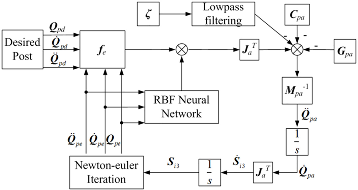
Flowchart of the ASMC of the parallel working arm.
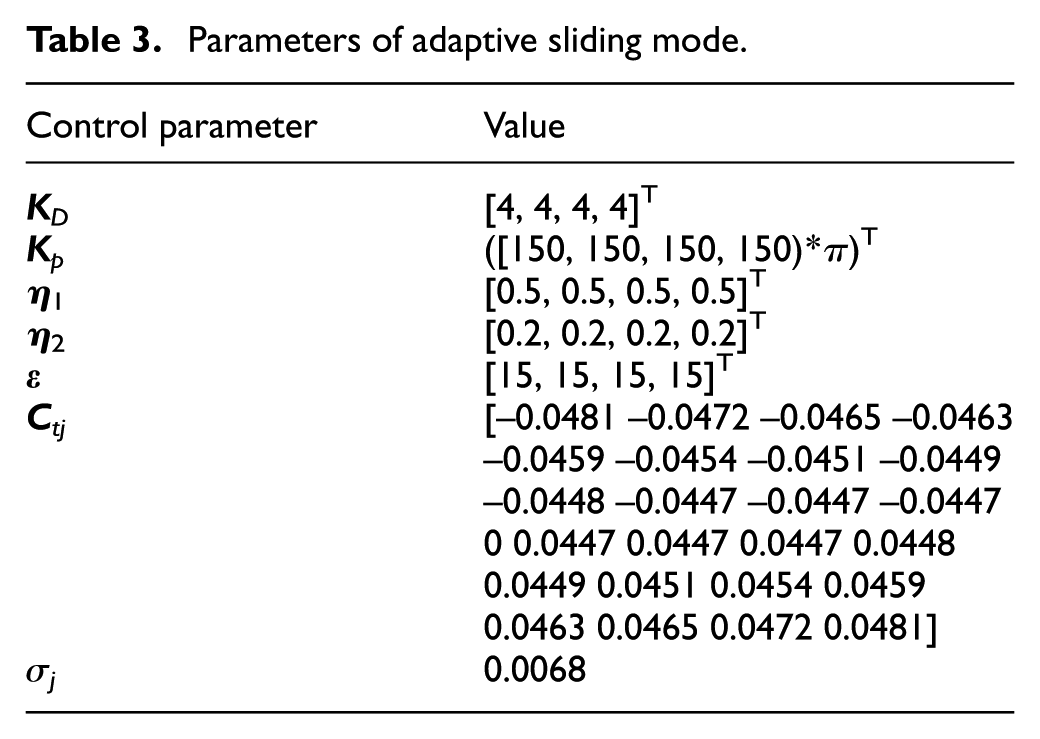
Parameters of adaptive sliding mode.
In Figures 9 and 10 (intercepting the first 8 s), it can be seen that the ASMC control law based on the RBFNN and the pose estimator is able to follow the desired pose, and relative to the general SMC control rate has a higher (about 2 times) convergence speed, a higher convergence accuracy, and a smaller error fluctuation in the desired pose.
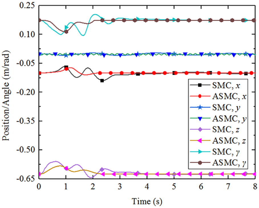
Position and angle results in x, y, z, and γ directions.
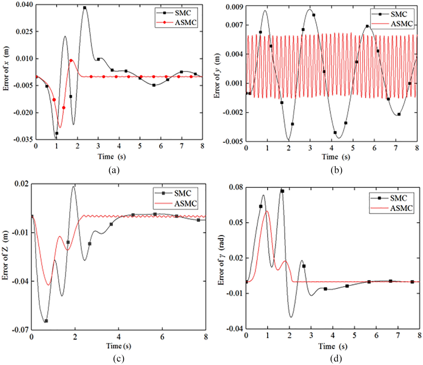
Position and angle errors in (a) x, (b) y, (c) z, and (d) γ directions.
MATLAB/Simulink—ADAMS co-simulation
To further verify the reliability of the ASMC control law, the MATLAB/Simulink—ADAMS co-simulation was established. The three-dimensional (3D) model was built in Creo according to the parameters of Table 2 and imported into ADAMS, as shown in Figure 11. Add the necessary fixed pairs, moving pairs and rotating pairs, and the quality of each part is set according to Table 2. The driving force/driving torque in MATLAB is used as the ADAMS input, and the motion parameters of the ladle in the ADAMS are input as MATLAB. Apply the acceleration data in section “Numerical analysis of control schemes” to the ladle, and the simulation time is still set to 8 s. The result is shown in Figure 12.
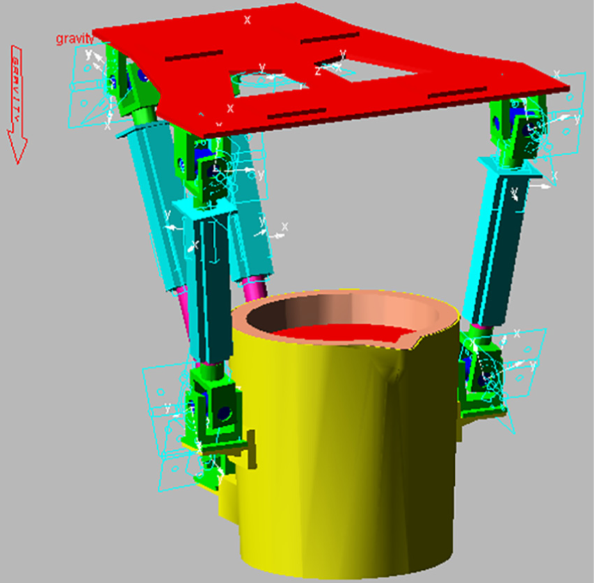
Model of the parallel working arm in ADAMS.
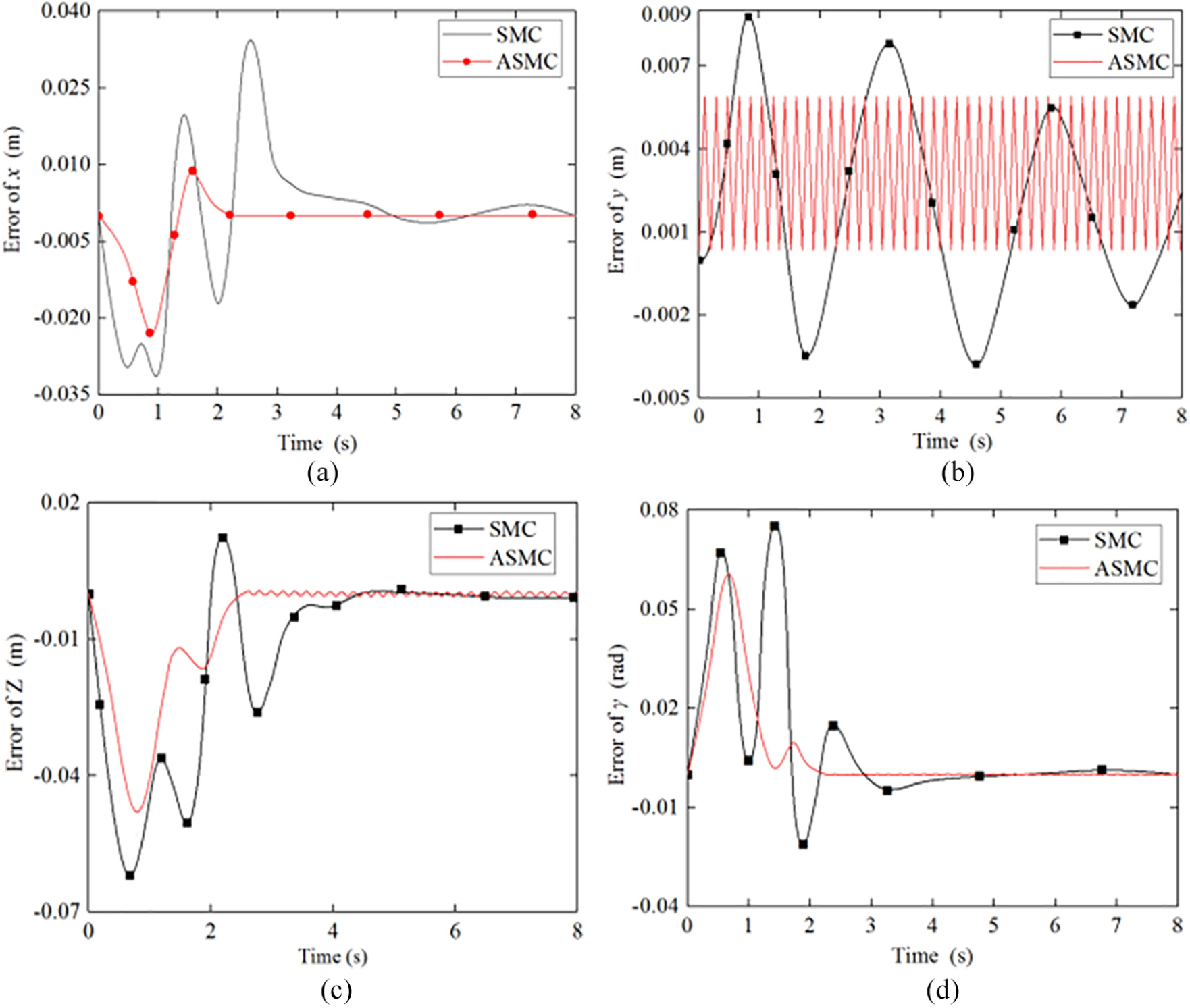
Errors in the (a) x, (b) y, (c) z, (d) and γ directions in the simulation experiment.
Comparing Figures 10 and 12, the numerical analysis and simulation results are basically consistent. This indicates that the ASMC control law is correct and effective, the ASMC control law is better than the SMC control law, and the proposed pose control method has excellent performances such as fast response speed, small overshoot, and high tracking precision. It also verifies the correctness of the dynamic modeling of the parallel working arm established in this paper.
Conclusion
In this paper, the designed pouring robot is taken as the research object, and the pose control method is taken as the research goal. The vibration dynamics equation and the parallel working dynamics equation of the pouring robot are studied. Based on RBFNN and Newton iteration, a method suitable for pose control of pouring robot is proposed. The main conclusions are as follows:
Using the static–dynamic method to simplify the cantilever structure of the pouring robot into a 2-DOF forced vibration system, and based on the isolation method, the 9-DOF vibration dynamics equation of the whole machine is established. The vibration analysis in the frequency domain and the time domain shows: there are multiple resonance peaks in the whole vibration frequency range, and the low-frequency resonance interval includes the road frequency. So, the design should change the structure to avoid resonance as much as possible.
The Jacobian with rotation and translation coupling is established. The 4-DOF dynamic equation of the parallel working arm driven by torque and force is established by Kane method. The numerical analysis verifies the correctness of the model.
Using the sliding mode controller of RBFNN and Newton iterative estimator to track the pose of the ladle, Lyapunov theory proves the stability of the control. The simulation results show that the proposed method has good control performance, fast response, high convergence precision, and excellent robustness.
Footnotes
Appendix 1
Acknowledgements
The authors thank the anonymous reviewers for their valuable comments and suggestions.
Declaration of conflicting interests
The author(s) declared no potential conflicts of interest with respect to the research, authorship, and/or publication of this article.
Funding
The author(s) disclosed receipt of the following financial support for the research, authorship, and/or publication of this article: This work was supported by the National Key Research and Development Program of China (Grant No. 2018YFC0309102), Postgraduate Research and Practice Innovation Program of Jiangsu Province (No. KYCX18_0260), The Major Science and Technology Projects of Anhui Province of China (No. 16030901012), and Key Research and Development Plan Project of Anhui Province of China (No. 201904a05020092).