
Abstract
This article proposes a new reconfigurable parallel mechanism using a spatial overconstrained platform. This proposed mechanism can be used as a machine tool. The mobility is analyzed by Screw Theory. The inverse kinematic model is established by applying the closed-loop equation. Next, the dynamic model of the presented mechanism is established by Lagrange formulation. To control the presented mechanism, some controllers have been used. Based on this dynamic model, the fuzzy-proportion integration differentiation (PID) controller is designed to track the trajectory of the end effector. For each limb, a sliding mode controller is applied to track the position and velocity of the slider. Finally, some simulations using ADAMS and MATLAB are proposed to verify the effectiveness and stability of these controllers.
Keywords
Introduction
Over the past few decades, developing reconfigurable parallel mechanism has become a noticeable trend for researchers due to the necessity of flexible industrial requirements. 1 –3 The reconfigurable parallel mechanism can change its configurations to obtain different performances, and it also has the advantages of traditional parallel mechanism, like highly dynamic movement and low inertia and positioning errors. 4,5 Based on these attractive characteristics, the reconfigurable parallel mechanism (RPM) has been widely used in many industrial areas, such as machine tools, 6 –9 3-D printers, 10,11 gripper, 12 rehabilitation manipulator, 13 and sensors. 14
Recently, parallel mechanism with reconfigurable structure or function has been applied in modern industrial fields. Therefore, many researchers have done a lot of work to design and manufacture variable reconfigurable parallel mechanism. The initial presented reconfigurable parallel mechanisms change their configurations by attaching or detaching some modular components. 15,16 While, it’s not convenient to change their performances. Thus, using metamorphic mechanism, some reconfigurable parallel mechanisms are designed to develop variable performances. 17,18 These mechanisms can obtain different configurations by altering some linkages into different working modes. Similar to this way, some metamorphic joints are presented to change their configurations to develop different mobility variations. 19,20 However, the first way needs to attach or detach some components and the rest ways need to pass the singularity points to obtain different configurations, which means all the above methods need manual intervention. In this case, some reconfigurable parallel mechanisms with continuous changing characteristic are proposed. 21 –24
As the significant characteristic, kinematic performance has a great impact on the application of the mechanism. 25 Thus, some scholars focus on this topic and have done some work on it. For the planar parallel mechanism, Liu et al. 26 addressed a performance evaluation and kinematic optimization to make this planar manipulator obtain the larger workspace and more stable transmissibility. A novel performance called dexterous stiffness has been proposed to optimize a parallel mechanism by Zhang and Gao, 27 which can show the mean value and the standard deviation of the stiffness distribution. And, the mean value represents the average stiffness of the parallel manipulator over the workspace, while the standard deviation indicates the stiffness variation relative to the mean value.
It’s well-known that controller is a great important to operation of the manipulator. To control the parallel mechanism, the dynamic model should be established, firstly. Thus, several theoretical methods are proposed to solve dynamic problem. Based on Newton–Euler method, several works have been done. For a three-degree of freedom (DOF) micro/nano parallel mechanism, the flexure hinges are regarded as the revolute joints with constant torsional stiffness, then, the dynamic model is analyzed.
28
Considering the friction between joint components caused by joints clearances, the dynamic model of a 3-
The trajectory control for a parallel manipulator is important section in the industrial application. And, the control system of the parallel mechanism is typical nonlinear control system. Compared with linear systems, the nonlinear control system is imperfect and complex. Many methods for nonlinear systems are proposed to reduce the effect of nonlinear uncertainties, like nonlinear adaptive control, 37 adaptive sliding mode control, 38 fuzzy-PID control, 39 and so on. For general parallel mechanism, the prismatic joint is usually employed by the ball-screw system. For a piston air motor ball-screw system, the hybrid sliding mode position method is applied to accomplish this system accurate position performance. 40 To improve the machining accuracy of ball-screw feed-drive systems, a novel sliding mode controller with a nonlinear sliding surface is presented. And the energy in machining of feed-drive systems is considered to be reduced by this controller. 41 For controlling the whole parallel mechanism, uncertain and nonlinear system, fuzzy logic is considered to be an efficient and effective tool to manage it. 42 For a cable-driven parallel mechanism, Li et al. 43 presented a novel type-2 fuzzy neural network to approximate the inverse dynamics of the process and to handle uncertainties. A novel intelligent control scheme is presented to control the highly nonlinear 3-RRR planer parallel mechanism. 44 Using this fuzzy-PD controller, the trajectory of this planer parallel mechanism is tracked precisely compared to the conventional linear resolved acceleration control. Aiming to a high nonlinear and unknown disturbances system, a novel reconfigurable parallel mechanism, a sliding mode controller is designed for the ball-screw system of the prismatic joint. And a fuzzy-PID controller is designed to track the trajectory of the end effector.
In this article, a novel reconfigurable parallel mechanism is proposed by using a spatial overconstrained parallel mechanism. The mobility and structure of the proposed mechanism is introduced. Thus, the inverse kinematic of the proposed mechanism is calculated. To verify the correctness of the kinematics model, the simulation is performed in the Online Appendix using ADAMS. The dynamic model both for the reconfigurable section and parallel section is established by Lagrange method. Next, the position and velocity of the ball-screw system are both tracked by using an adaptive sliding mode controller. And the trajectory of the end-effector is tracked by using a fuzzy-PID controller. To build the control system, MATLAB Simscape Multibody Toolbox and ADAMS-MATLAB co-simulation 45,46 are becoming the useful tool. In the fourth section, the control system is built using Simscape Multibody Toolbox, whereas the ADAMS-MATLAB co-simulation approach is used to build the closed-loop system in the Online Appendix. The simulations are presented at the end of each section. Finally, the conclusions are obtained.
Manipulator design and mobility analysis
The reconfigurable parallel mechanism consists of two sections: (1) the reconfigurable section, which is designed by the spatial multi-loop overconstrained parallel mechanism; (2) the parallel section, which is designed by a traditional 3-DOF parallel mechanism. As shown in Figure 1, the two section both have three identical limbs, and they are connected by three prismatic joints. For the parallel section, these prismatic joints are actuators to drive the end effector. Considered the stiffness of the reconfigurable parallel mechanism, the reconfigurable parallel mechanism has three platforms. The bottom platform is the fixed platform located at the ground. The middle platform is the end effector of the reconfigurable section and the top platform is the end effector of the parallel section. Besides middle and fixed platforms, the reconfigurable section includes three limbs and three sliders. The joints between fixed platform and sliders are prismatic and each limb uses revolution joints to connect slider and middle platform. The parallel section also has three identical limbs and each limb includes prismatic joint and two universal joints. By driving the reconfigurable section, the structural parameters of the parallel section can be changed, thus, the different configurations of the reconfigurable parallel mechanism can be obtained.

The CAD model of the reconfigurable parallel mechanism.
The schematic of reconfigurable section is shown in Figure 2. The reconfigurable section is also a parallel mechanism which has three identical limbs. Based on its structure, the middle platform can only move along the z-axis. And its mobility can be analyzed by Screw Theory.
The schematic of the reconfigurable mechanism.
To analyze its mobility, the coordinates can be given as

where ai and bi are the directions of prismatic joint.
The wrench system of this limb can be written as

According to equation (2), the twist system of reconfigurable section can be calculated as

Finally, the mobility of the reconfigurable section is proved.
The schematic of the parallel section is shown in Figure 3. The mobility of the parallel section can be analyzed by Screw Theory as well. The coordinates of the points Di
, Ei
, and Fi
are given as
where li
, mi
, and ni
are the directions of prismatic joint; ai
, bi
, and ci
are the direction of one of the universal joint. The direction of the other joint is


The schematic of the parallel section.
So, the wrench system of the limb
According to equation (6), the twist system of the parallel section can be written as

Equation (7) shows that the parallel section has three translations along x, y, and z axes.
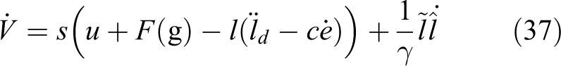
Kinematic and dynamic analysis
Inverse kinematics
When the parallel section is working, the reconfigurable section is locked at a certain position. Namely, the kinematics model of the parallel section is different, while the reconfigurable parallel is located at different positions. To solve the inverse kinematics of the parallel section, the first step is to obtain the mathematical model of the reconfigurable section. For the reconfigurable section, the input parameter is m and the output parameter is zr . When the prismatic joint is driving, the middle platform will be located at a certain altitude and the structural parameters of the parallel section will be changed as well.
Based on Figure 2, the closed-loop vector equation of the reconfigurable section can be written as

Thus, the kinematics model of the reconfigurable can be calculated as

where d is the length of the link
For the parallel section, the inverse problem is that the position of the end effector is known to solve the lengths of three driving joints. As shown in Figure 3, the point O
2 is in the center of the end effector and the point O is the original point of the fixed coordinate system. In this article, the coordinate of O
2 is
Based on the structural constraints, the closed-loop vector equation can be given as

And the vector of

where θ is the angle between

In the moving coordinate system, the coordinate of point O
2 is

To transfer the vector from moving coordinate system to the global coordinate system, the vector should be multiplied a rotation matrix. Fortunately, the type of the DOF of the moving platform is only the translation, namely, the rotation matrix can be given as

Thus, the coordinate of F 1 in the global coordinate system can be calculated as

Based on the geometrical constraint, the length of the identical link

Substituting equations (13) and (15) into equation (16), the inverse kinematics of the parallel section can be obtained.
For the further analysis, the structural parameter is listed in Table 1.
The structural parameters of the mechanism.

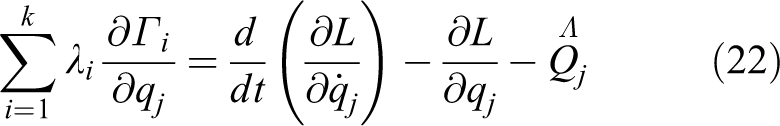
Dynamics model for the overconstrained mechanism
Based on the Virtual Work Theory, the inverse dynamics equation of the overconstrained mechanism can be given as

where
Based on equation (9), the Jacobian matrix of the overconstrained mechanism can be written as
Thus,

Substituting equation (19) in equation (17) yields

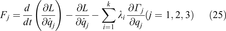
Dynamics model for the parallel section
Compared with the overconstrained mechanism, the inverse dynamics model of the parallel mechanism is more complex. According to its structural characteristic, the Lagrangian Theory is suitable to be applied. For the parallel section, there are three redundant coordinates, x, y, and z, employed for the first type of the Lagrangian equations. Then, x, y, z and

where
To solve three Lagrange multipliers, equation (21) can be written as
where
For simplifying the dynamics analysis, the mass of each rod can be assumed to divide into two endpoints, Fi and Ei , denoted as mb . Thus, the total energy of the parallel section can be given as

where mp
is the mass of the parallel platform and
Based on equation (16), the three constraint equations can be given as

Then, the Lagrangian multiplier,
Based on equation (25), the equation can be rewritten as matrix formulation, which is

where
In this article, the Lagrangian multipliers matrix can be written as

where
Control system design
Adaptive sliding mode control
Control model and design of adaptive controller
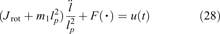
For the parallel mechanism, each limb is nonlinear uncertainties control system. In this article, the driving joint is the prismatic joint, but the motor is a DC servo disc motor. Thus, a ball-screw system is used through a helical coupling. And the driving system setup is illustrated in Figure 4. In this case, the rotational dynamics of ball screw can be described as follows
47
where

where

Conceptual model of the ball-screw system.
For a certain ball-screw system,
Assuming 1
The uncertain parameter

Assuming 2
The uncertain nominal

Thus, the sliding surfaces in this article is chosen as

where ld
is the desired position and

where
Stability analysis
Stability is a significant index for the control system. Considered as a nonlinear uncertain dynamical system, the ball-screw system is described as equation (29) and the adaptive control law, equation (33), is applied. At the same time, asymptotic stability of the closed-loop system in the presence of model uncertainties and disturbance must be guaranteed.
Proof
To prove the stability of the proposed controller and to derive an estimation law for the unknown equivalent friction force

where
From equation (34), the derivative of Lyapunov function is as

Substituting equation (32) into equation (35) yields
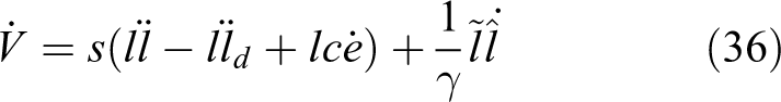
Then, equation (36) can be rewritten as
where u is the control law shown in equation (33) and
Substituting equation (33) into equation (37) yields

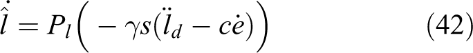
In this article, the adaptive control law is designed as

Thus, equation (38) can be written as

Thus,

Based on equation (41), if
And

where
Based on the proposed adaptive sliding mode controller, the block diagram of the controller is given as Figure 5.

Block diagram of the adapt sliding mode controller with perturbation force.
PD control
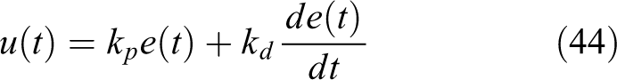
For this ball-screw system, a PD controller is presented based on equation (29). As a comparison, a PD control law can be expressed via the following equation
In which

where
Simulation result
In this simulation, it’s assumed that

And the input signal is the length of the prismatic joint calculated by equation (16) and the trajectory of the end effector is given in equation (47). While, the input is too complex to simulate slowly. To simplify the signal, curve fitting is applied in this article.

Based on Fourier Fitting Method, the fitting result of three driving joints is shown in Figure 6. The Fourier formulation is given as

Thus, the coefficients of three limbs are listed in Table 2. And the result is shown in Figure 6. The points in Figure 6(a), (b), and (c) are the actual positions of the driving joints and the blue, green, and red lines represent the fitting curves based on Fourier Fitting Method. Their trends are similar and the fitting curves can replace the discrete points very well. Thus, the fitting equations can be regarded as the input function.
The coefficients of three limbs.

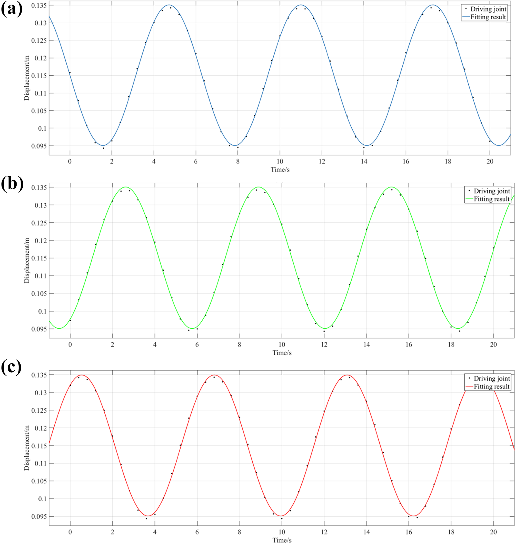
The comparison between driving joints and fitting curves, (a) first joint, (b) second joint, and (c) third joint.
The results of the sliding mode control are shown in Figures 7 to 9. In this PD control,

The desired and actual displacement and velocity: (a) displacement, (b) velocity, (c) local enlarging graphs of displacement, and (d) local enlarging graphs of velocity.
The errors of both displacement and velocity: (a) displacement, (b) velocity, (c) local enlarging graphs of displacement, and (d) local enlarging graphs of velocity.

Other results: (a) control input, (b) phase trajectory, (c) equivalent mass, and (d) equivalent force.

The results of PD control: (a) displacement, (b) velocity, (c) error of displacement, and (d) error of velocity.
Fuzzy-PID control
For the trajectory tracking, the mathematical dynamic model of the parallel mechanism is established in equation (26). Based on equation (26),

In this case, traditional PID controller with fixed control parameters is not suitable for this reconfigurable parallel mechanism. Thus, fuzzy PID controller with changing control parameter can be applied to control this mechanism.
Traditional PID controller
Similar to equation (44), the transfer function of a traditional PID controller for the proposed mechanism can be given as

Here,
Design of fuzzy PID controller
For this reconfigurable parallel mechanism, its control scheme is a kind of tracking control. Here calculate the forces of the prismatic joints that the end-effector is moving with the desired trajectory in the Cartesian coordinate system. Specially, we hope that the end effector can follow the desired trajectory and the prismatic joints are given in terms of forces. Almost always, these driving forces are determined using the feedback from the mathematical dynamic model to calculate the forces required for a desired trajectory. The PID parameters of the whole parallel mechanism are tuned by comparing both the error and differential of the error between actual and desired trajectory of the end effector. 48 For each limb, the proposed sliding mode control is applied, thus, the control scheme of the whole parallel mechanism is shown in Figure 11.

The whole control scheme.
It is assumed that Kp
and Kd
are in estimated ranges


where
For the fuzzy controller, the input parameters are

Fuzzy membership functions.
Fuzzy rules for Kp .

Fuzzy rules for Kd .

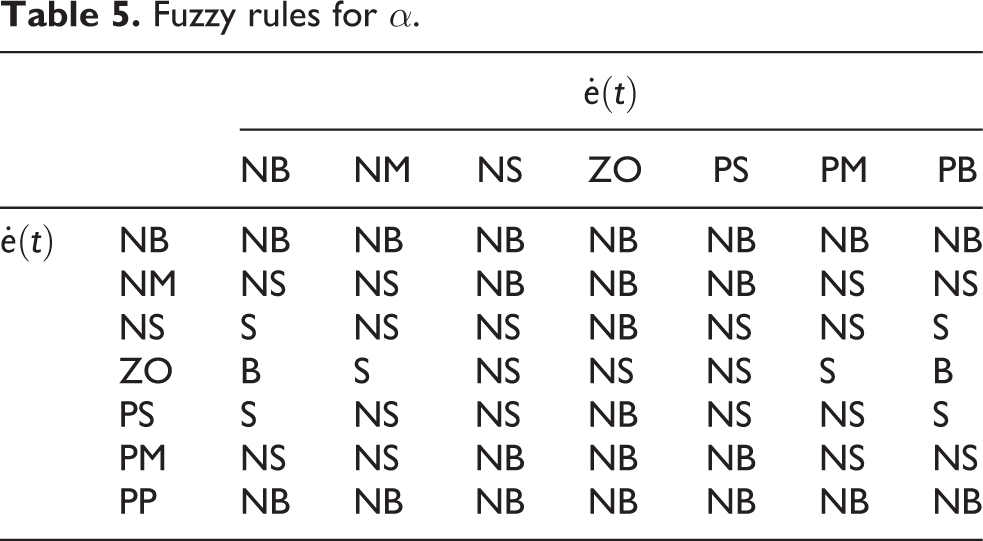
Fuzzy rules for α.

The rules’ surface for α.

The rules’ surface for Kd .
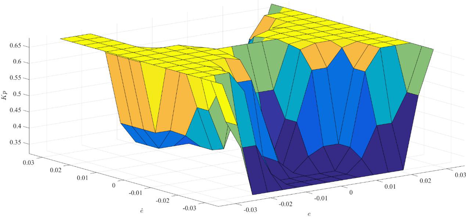
The rules’ surface for Kp .
Simulation result
In this simulation, the simulation time is 10 s. The traditional PID control gains are tuned by the expert experience, thus, the parameters are chosen as follows: proportional gain
Dynamic parameters of the proposed mechanism.

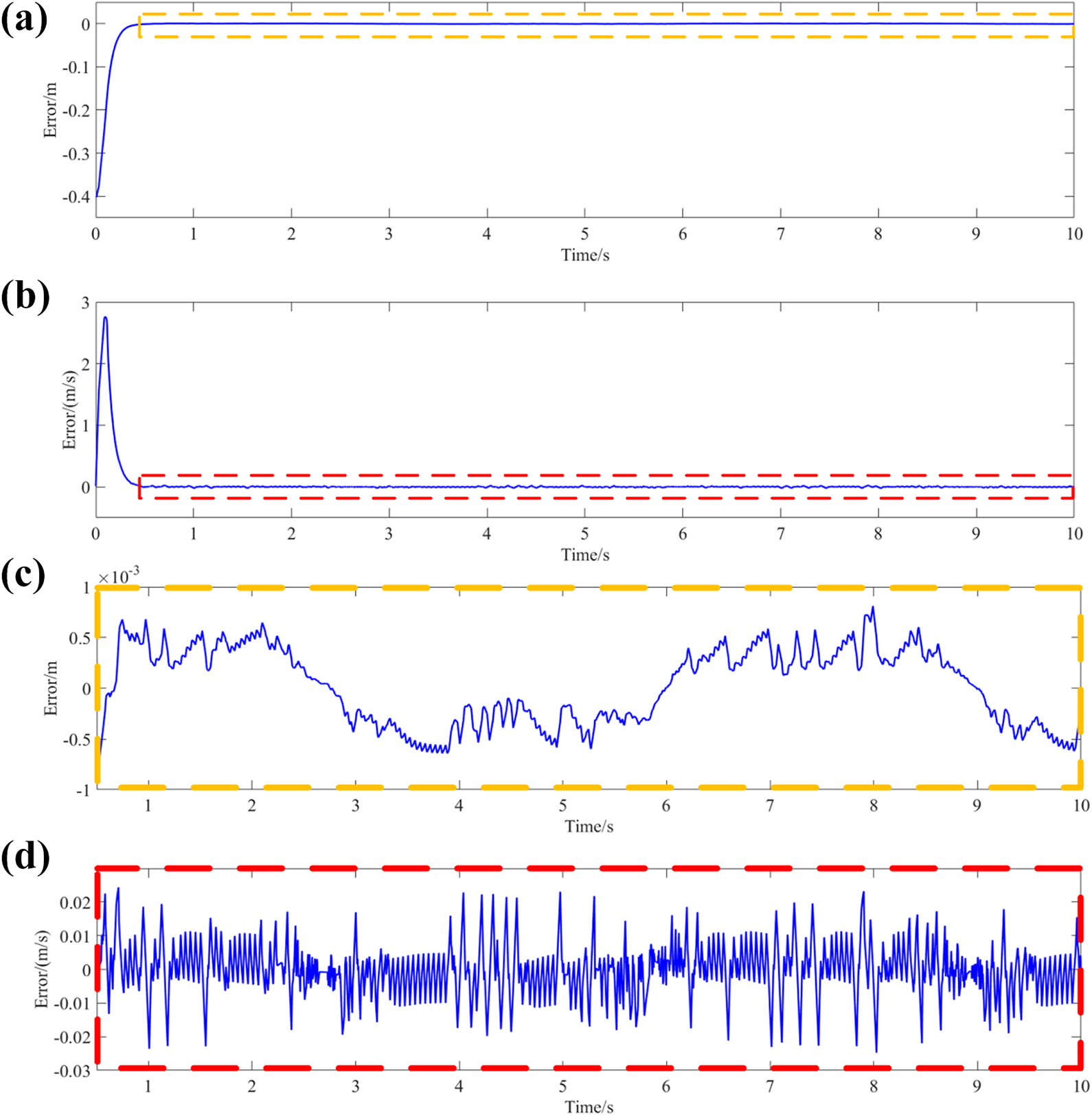
Using Simscape Multibody toolbox in Simulink, the results of the simulation are shown in Figures 16 to 25 and Online Supplementary Figures 26 to 34. Figure 16 shows the trajectories of the end effector under fuzzy-PID control and traditional PID. It can be seen from it, the fuzzy PID control can track the desired trajectory better than traditional PID control and its error along
where

The trajectory of the end effector: (a) fuzzy-PID and (b) traditional PID.
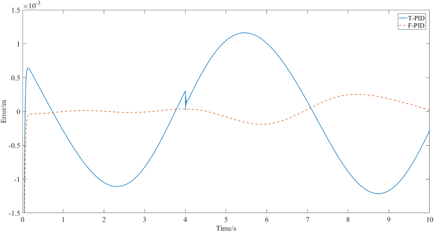
The error along

The error along

The lengths of driving joints under traditional PID control.

The velocities of driving joints under traditional PID control.
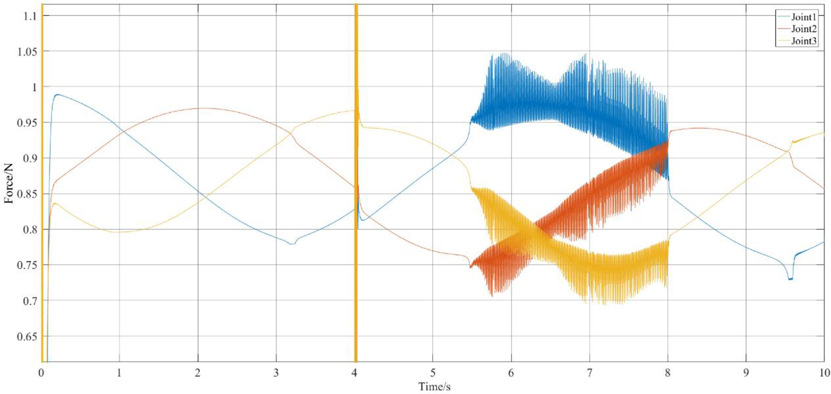
The forces of driving joints under traditional PID control.

The lengths of driving joints under fuzzy-PID control.

The velocities of driving joints under fuzzy-PID control.
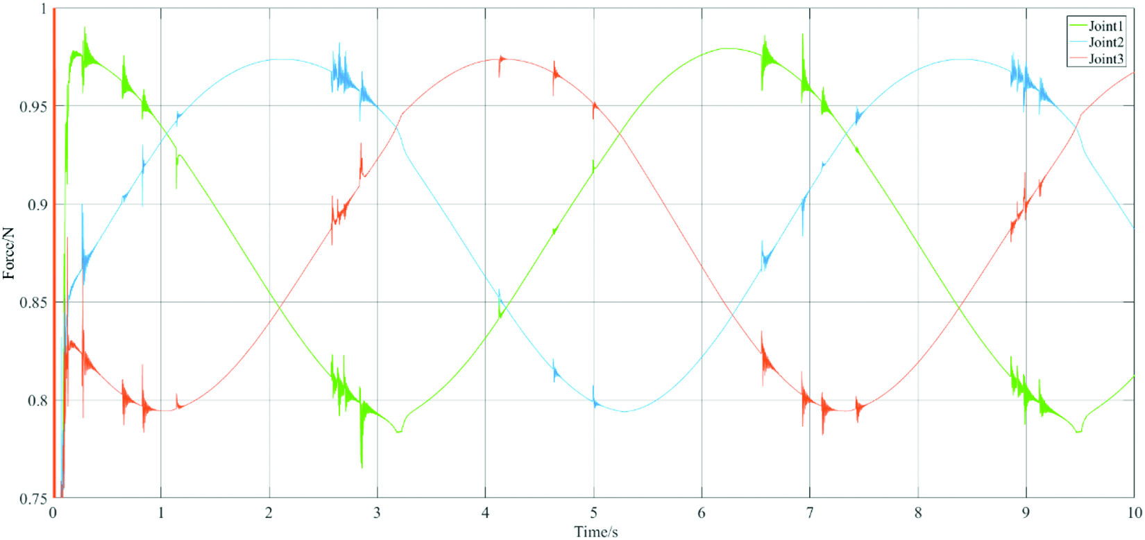
The forces of driving joints under fuzzy-PID control.
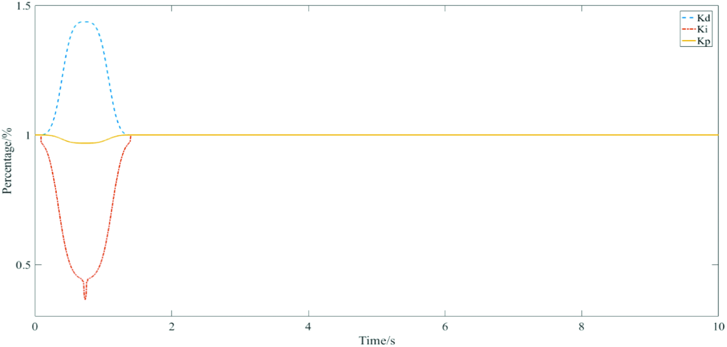
Thus, the trends of three PID parameters are shown in Figure 25. The blue, red, and yellow lines represent Kd , Ki , and Kp , separately. Between 0.1th second and 1.8th second, the fuzzy rules are applied to tune these PID parameters and after 1.8th second, the parameters become stable.

The changing trends of fuzzy-PID control parameters.
Conclusions
In this article, a reconfigurable parallel mechanism based on spatial overconstrained mechanism is proposed based on Screw Theory. This reconfigurable parallel mechanism can change its structural parameters continuously, which makes it has variable performances. The CAD model and its kinematic mathematical model have been established. Next, the dynamic model of this reconfigurable parallel mechanism has been established by utilizing the Lagrange formulation. To control the limb of this mechanism, an adaptive sliding mode has been designed to track the position and velocity of the desired driving curves. The control law and adaptive law have both been presented, as well. Compared with traditional PD control, a simulation has been presented to verify the efficiency of this adaptive sliding controller in Simulink. For the whole reconfigurable parallel mechanism, a fuzzy-PID control has been applied to track the trajectory of the end effector by using Simscape Multibody toolbox in Simulink. Finally, a simulation has been proposed to verify the effectiveness and correctness of this fuzzy-PID control. Compared with traditional PID control, this fuzzy-PID controller can work more smoothly and flexibly.
Supplemental material
Supplemental Material, Appendix - Analysis and control for a new reconfigurable parallel mechanism
Supplemental Material, Appendix for Analysis and control for a new reconfigurable parallel mechanism by Guanyu Huang, Dan Zhang, Hongyan Tang, Lingyu Kong and Sumian Song in International Journal of Advanced Robotic Systems
Footnotes
Declaration of conflicting interests
The author(s) declared no potential conflicts of interest with respect to the research, authorship, and/or publication of this article.
Funding
The author(s) disclosed receipt of the following financial support for the research, authorship, and/or publication of this article: The work was financially supported by the Youth Foundation of Zhejiang Lab (Grant No. 2020NB0AA02), the Natural Science Foundation of Zhejiang Province of China (Grant No. LQ20E050008), the Leading Innovation and Entrepreneurship Team of Zhejiang Province of China (Grant No. 2018R01006), the Natural Sciences and Engineering Research Council of Canada (NSERC), and the York Research Chairs (YRC) program.
Supplemental material
Supplemental material for this article is available online.
References
Supplementary Material
Please find the following supplemental material available below.
For Open Access articles published under a Creative Commons License, all supplemental material carries the same license as the article it is associated with.
For non-Open Access articles published, all supplemental material carries a non-exclusive license, and permission requests for re-use of supplemental material or any part of supplemental material shall be sent directly to the copyright owner as specified in the copyright notice associated with the article.