
Abstract
This work mainly deals with replacing the wired power transmission method for charging electric vehicle with the help of an efficient wireless power transmission method. For identifying an efficient wireless power transmission method, the inductive power transfer method and the laser optic method are taken into consideration to charge the electric vehicle battery. These methods are compared by hardware implementation for various conditions. Wireless power transmission is an emerging technology utilized to charge the electric vehicle battery through an air gap. The use of this new charging technique is due to its easy access from annoying charging cables, better efficiency, and smaller charging time. Also, it contributes to the remarkable reduction of pollutants and carbon dioxide (CO2) emissions into the atmosphere by the conventional vehicles. However, the implementation of inductive charging for electric vehicle still presents challenges in terms of power transfer efficiency, transmission distance, utilization of heavy batteries with ripple-free and charging time, and stress on compensation network to maintain resonant condition for maximum power transfer. This system will be verified through the simulation in MATLAB/Simulink environment. The simulation results of the inductive power transfer method and the comparison of hardware setup results with laser optic hardware setup have to be verified.
Introduction
In the modern era, most of us are using conventional vehicles for transportation which is the primary factor for global warming and the adverse damage of the ozone layer. To protect the quality of air surrounding us, we need to replace petrol/diesel-based vehicle with electric vehicle (EV). The solution for this is to use battery-operated vehicle with some challenges to be faced, that is, charging the battery with wired connection for moving vehicle, which is impossible for longer distance; increasing the life span and reliability; and low-maintenance operation of the battery.
The above-mentioned challenges are successfully met by inductive charging of battery with charge controller like an efficient DC-DC converter. In this research work, LUO converter (boost converter) performance is checked for battery charging; as the distance between primary and secondary coils is increased in the inductive charging method of battery, the output voltage (secondary side) will be reduced by the factor of coefficient of coupling. To charge the vehicle battery, sufficient power is required which can be obtained with the help of LUO converter. Manual operation of plugging, unplugging of charger, and electric shock can be avoided by the inductive charging method. The existing block diagram is shown in Figure 1, where the control of voltage is made only on the primary side of the coil; therefore, due to fixed-frequency operation in the primary side inverter, this existing system is inefficient to control the secondary side voltage. To get the required voltage in the secondary side (receiver coil end), there may be chances of transmitting coil or core saturation on high-power application. And as the inverter is a square wave type, harmonics will be high in the output of the inverter due to these above-mentioned issues in the existing system, which will lead to poor performance and less efficiency in implementing battery charging.
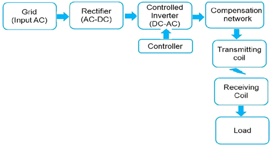
Block diagram of inductive charging system without secondary side control.
Figure 1 shows the inductive charging system 1 without secondary side control of voltage. It consists of AC supply of 230 V, and next the rectifier block will convert AC to DC. This DC is fed as an input for the inverter which will be under the control of dsPIC30f2010 controller, then the transmitting coil with compensation network is transferred with high-frequency AC to the secondary coil through the air gap, and finally, the LED load will receive the power from the receiving coil. The major drawback in this system is that according to the load, the secondary side voltage is uncontrolled; therefore, it is unable to drive effectively under load-varying conditions. Also, losses associated with the inductive power transfer (IPT) method are very high. Consequently, for better efficiency and safe method of wireless power transmission, laser optic method is used, which will not be diverted easily by any external source and distance variation 2 between the transmitter and the receiver; so, through the laser optic method, power will be transmitted without much loss in the air gap.
In the laser optic method, the laser beam is generated by the laser light source by providing the required input supply for the laser light. These laser light beams will focus on the solar panel, depending on the intensity 3 of the laser light and the distance between the laser light and the solar panel. The solar panel will convert that laser optic energy into electrical energy. Battery capacity may vary, and its operating voltage may also vary; accordingly, the laser optic source has to be changed by various kinds of batteries. But this method of increasing or decreasing the laser optic source is an inefficient method of charging the battery wirelessly. Sometimes due to aging factor of the laser optic source, laser beam intensity will be reduced which will affect the proper charging of the battery because solar cell output will be reduced. To charge the EV battery efficiently for various ground clearance, intensity variation from the laser optic source requires a DC-DC converter (LUO converter), that is, DC-DC converter–based inductive charging system.
Inductive charging system with secondary side control
Figure 2 shows the similar structure of Figure 1 except the secondary control with the LUO converter. Whenever the secondary voltage is not sufficient to meet the requirement of the battery charging or the load requirement, additional converter called LUO converter (DC-DC boost converter) 4 is connected to the secondary coil with a rectifier. The DC-DC converter is controlled separately with a separate controller to achieve sufficient supply for battery or load.
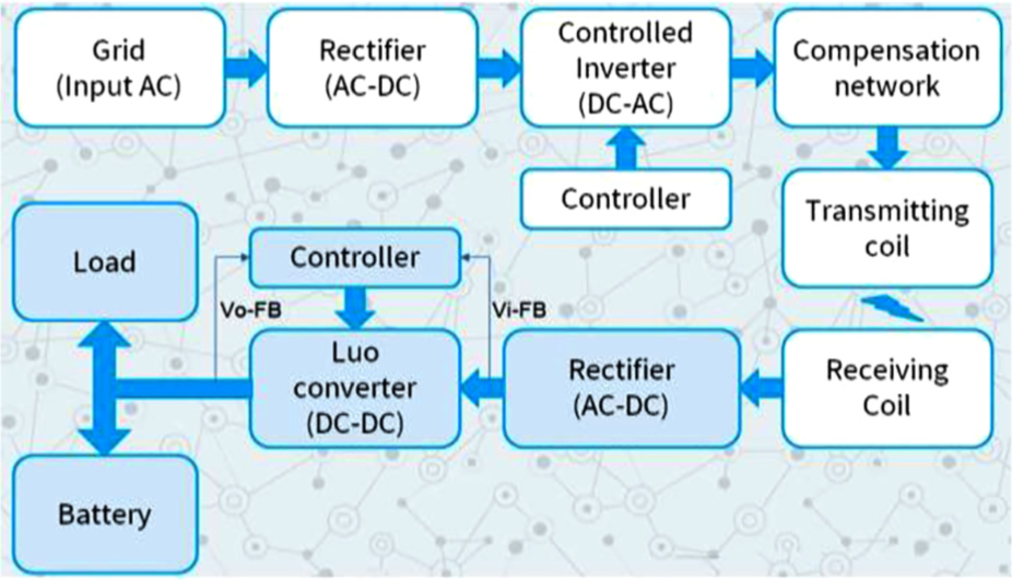
Block diagram of inductive charging system with secondary side control.
Proposed system of wireless power transmission by laser optic method with optimized power loss
Figure 3 illustrates the complete block diagram of wireless power transmission system for EV battery charging 5 by laser optic method. This method of charging is not affected by the losses that occur in air gap. 6 Also, the problem of tuning the resonance frequency 7 between the transmitting and the receiving coils in IPT to transfer maximum power can be avoided. The electrical energy supplied by the solar cell output can be given as an input for the laser light, which will produce laser optic energy that focuses on the other solar panel kept at the bottom of the EV. This results in the generation of electrical energy from the solar panel of the EV; this energy is constant and may not be sufficient to charge the EV battery, so it requires a DC-DC converter (LUO converter) to achieve proper charging of the battery available in the EV.
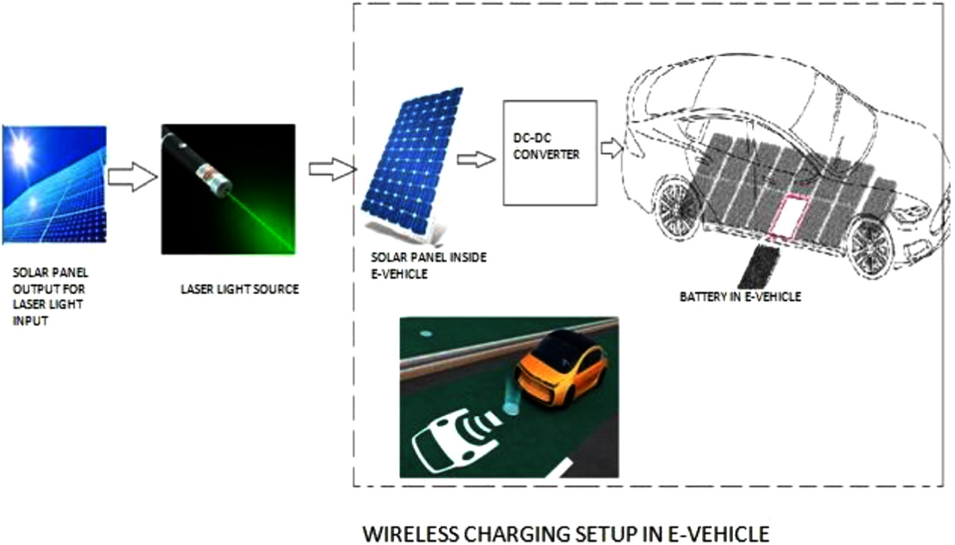
Block diagram of DC-DC converter–based laser optic power transmission system.
Simulation circuit of DC-DC converter–based inductive charging system and its result analysis
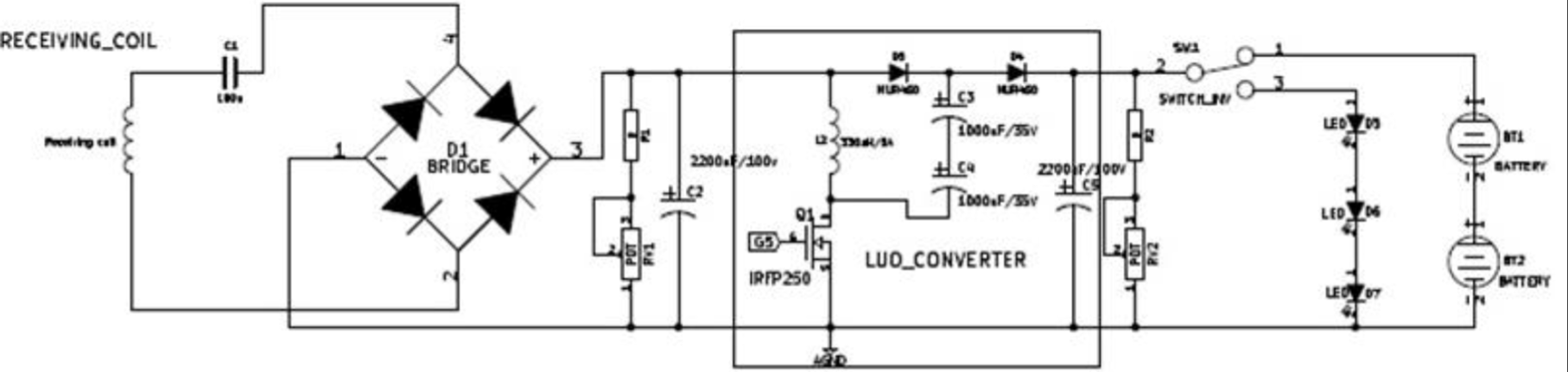
Figure 4 illustrates the complete circuit of LUO converter–based wireless power transmission system; it consists of primary side and secondary side circuit of the wireless transmission coil. This circuit is demonstrated and verified with various conditions, such as closed-loop condition, varying load, and various distance.
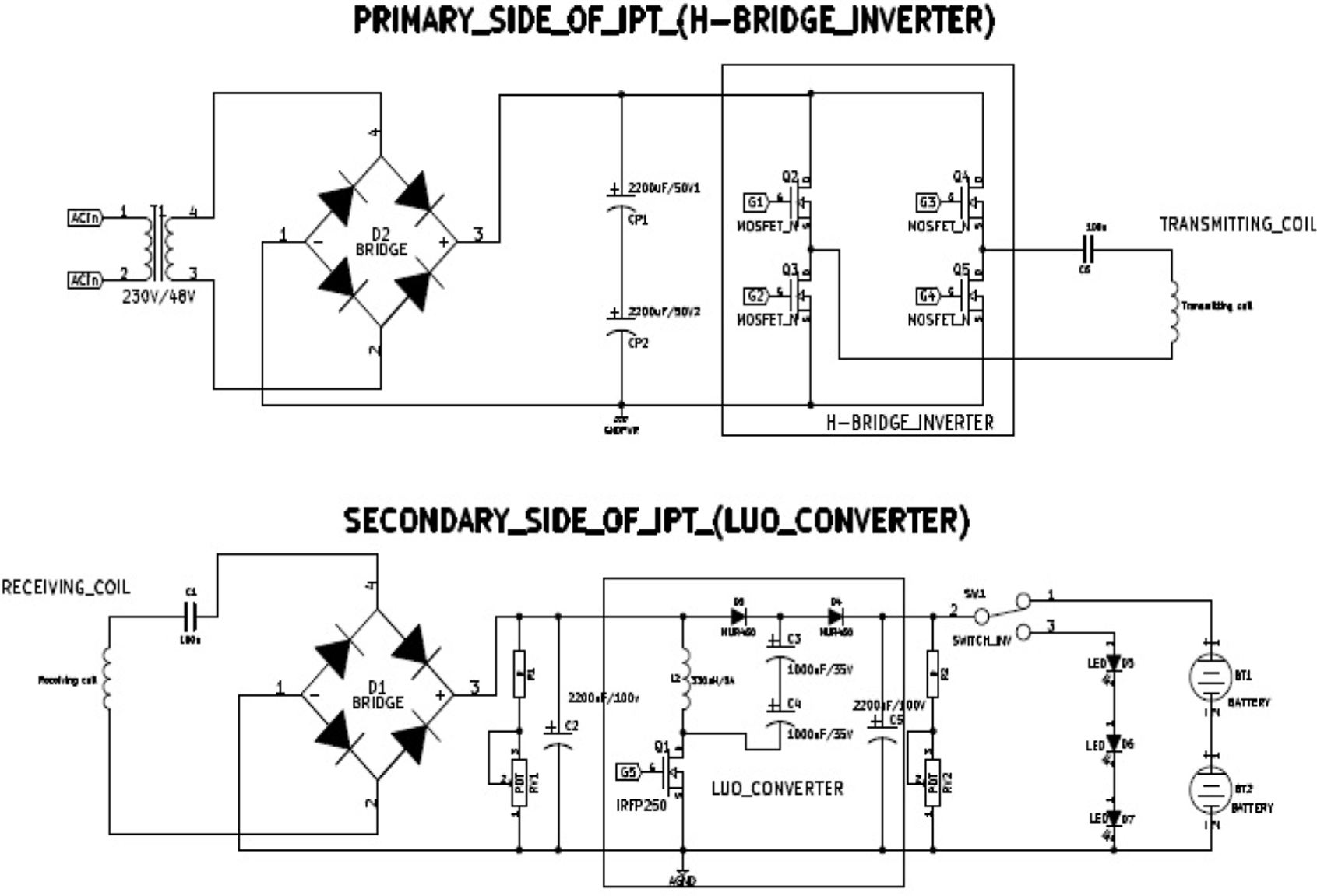
Complete circuit diagram of the IPT system.
Figure 5, along with Table 1, describes the closed-loop control waveform of H-Bridge inverter with a fixed load. This inverter waveform gives a set voltage of 35 V, while the closed-loop control attains 35 V in the primary side.
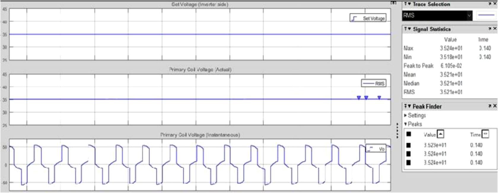
Inverter closed-loop control.
Closed-loop control waveform involved in following conditions.
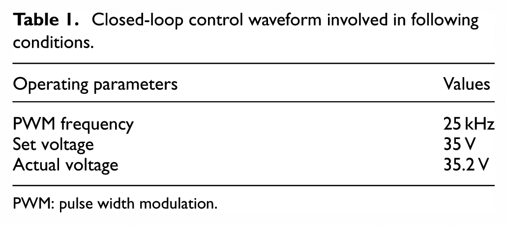
PWM: pulse width modulation.
The H-Bridge inverter is controlled in closed loop, and its response for load-varying condition is shown in Figure 6. The above waveform and Table 2 clearly indicate that, for varying load with various step times, the closed-loop-controlled inverter gives the required output according to the set voltage.

Inverter control for load-varying condition.
Load variation with time and current.
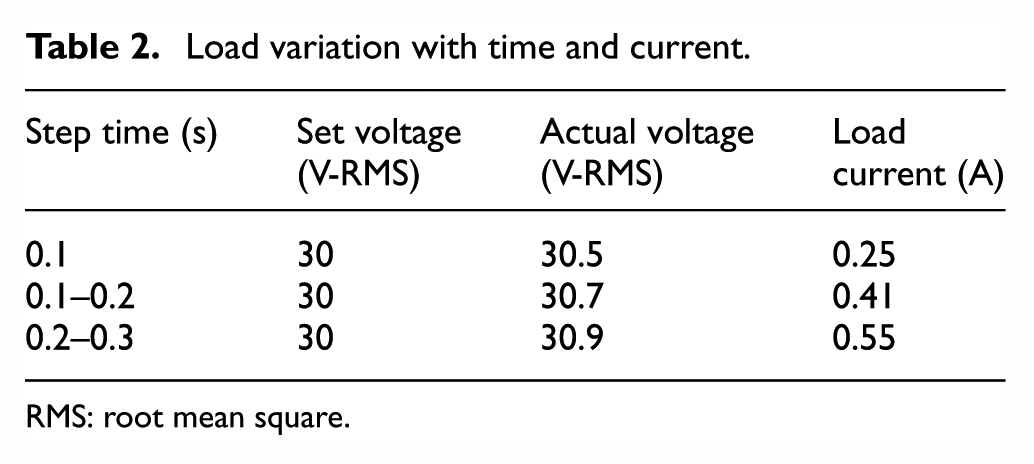
RMS: root mean square.
Operation and necessity of secondary side control using LUO converter
Essentially, the primary side voltage of the coil is controlled by inverter using proportional–integral (PI) controller, but the main problem in the primary side control is that voltage transmission in wireless mode is not much efficient to determine the load requirement which is connected to the receiving coil. Particularly, load at the output of the secondary side can withstand or can also be operated at lower voltage, for example, LED can even operate at 40% of the rated voltage. In the case of battery load at the output of the secondary side, for proper charging 8 of the battery, secondary side voltage should be more than the battery voltage. Hence, a system with primary side control alone is not capable to deliver or charge the battery as shown in Figure 7(a). To meet the requirement of the battery, secondary side control with an efficient DC-DC converter is required, which is shown in Figure 7(b). Simulation circuit of the secondary side control using LUO converter is shown in Figure 7(c).
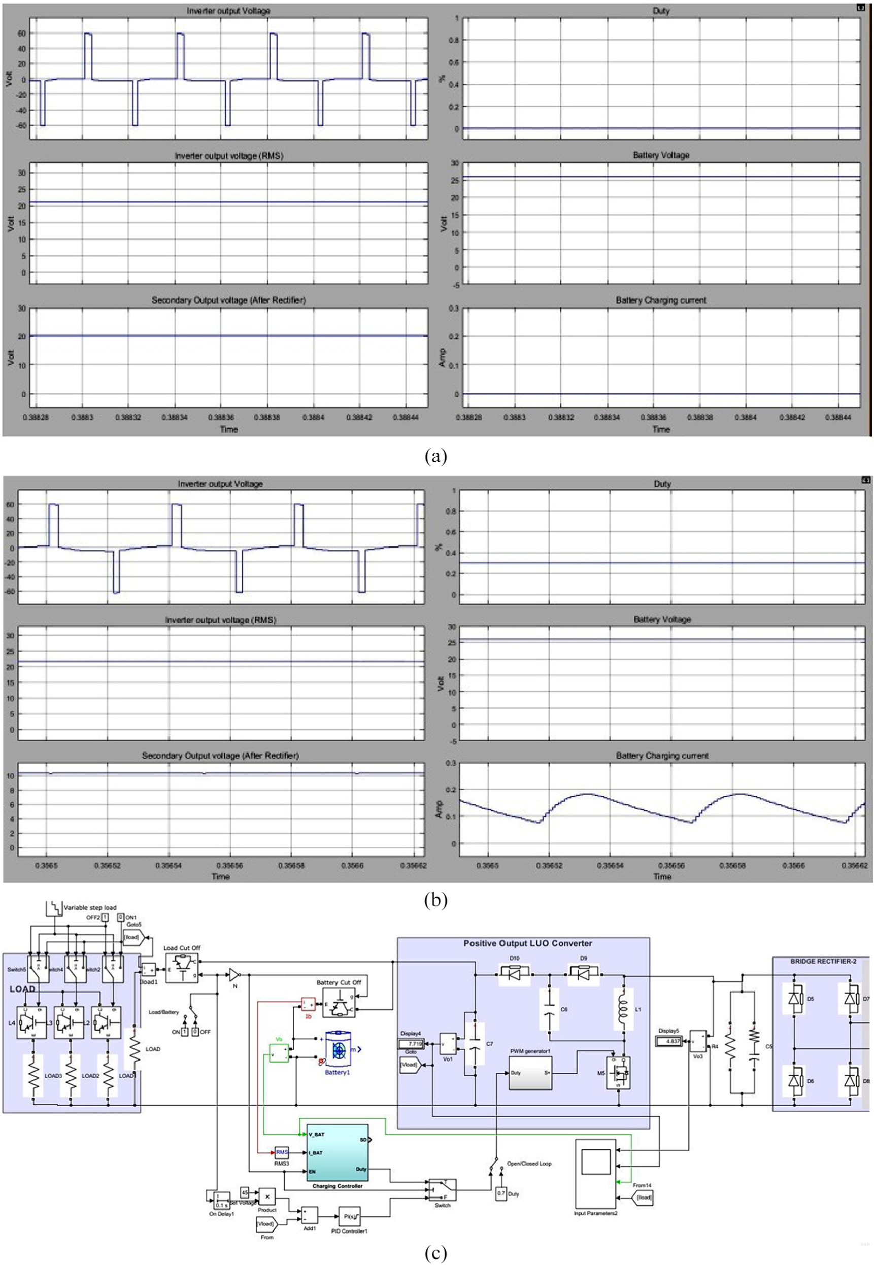
Secondary side control (a) without LUO converter and (b) with LUO converter; (c) simulation circuit of secondary side control with LUO converter.
Figure 8 shows the basic single-stage LUO converter 9 connected to the secondary side, which will take care of the battery 10 requirement according to the duty cycle variation of the set voltage in the closed-loop system.
Single-stage LUO converter.
Using MATLAB/Simulink, the LUO converter–based wireless charging system is shown in Figure 9. Secondary side control can be done efficiently according to the load. The secondary side of the system consists of an uncontrolled bridge rectifier and a DC-DC converter for voltage control which is applied to the load or battery. LUO converter is basically a high-gain DC-DC converter with single semiconductor switch (metal–oxide–semiconductor field-effect transistor, MOSFET). This switch can be controlled by a microcontroller; it is operated in two modes of operation such as open-loop and closed-loop control. Based on the switch input, the mode of operation is performed. Also, one of the switches is available for the selection of load or battery. Closed-loop control of the converter is done by the PI-based voltage control.
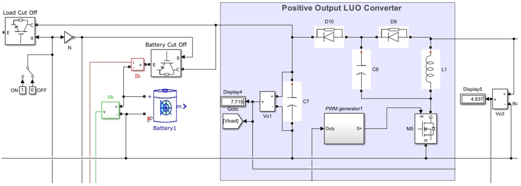
Simulation circuit of LUO converter.
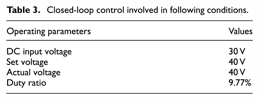
Figure 10 shows the secondary side control involved in voltage control with closed-loop operation. Here, for a duty ratio of 9.77% switching and frequency of 20 kHz, this closed-loop-controlled LUO converter provides 40 V in the output side for an input of 20 V, which is shown in Table 3.
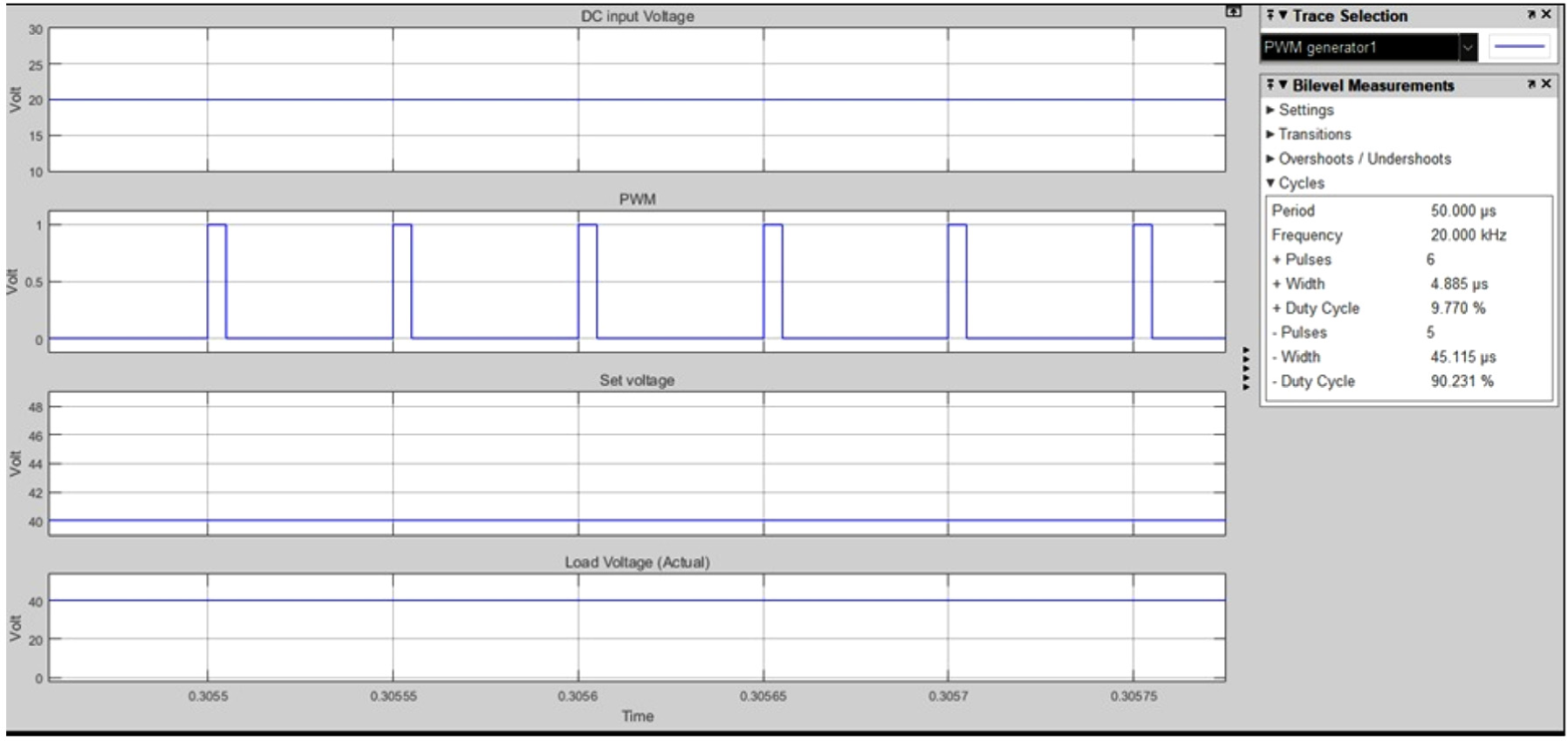
Waveform—closed-loop LUO converter.
Closed-loop control involved in following conditions.
The performance of the LUO converter in closed-loop condition for a varying load and varying set voltage is described in Figure 11. This LUO converter provides constant output according to the set voltage in the closed loop even if there is more variation in the load. Table 4 provides complete details on variation of the load, variation of the set voltage, and response of the closed-loop-controlled LUO converter.
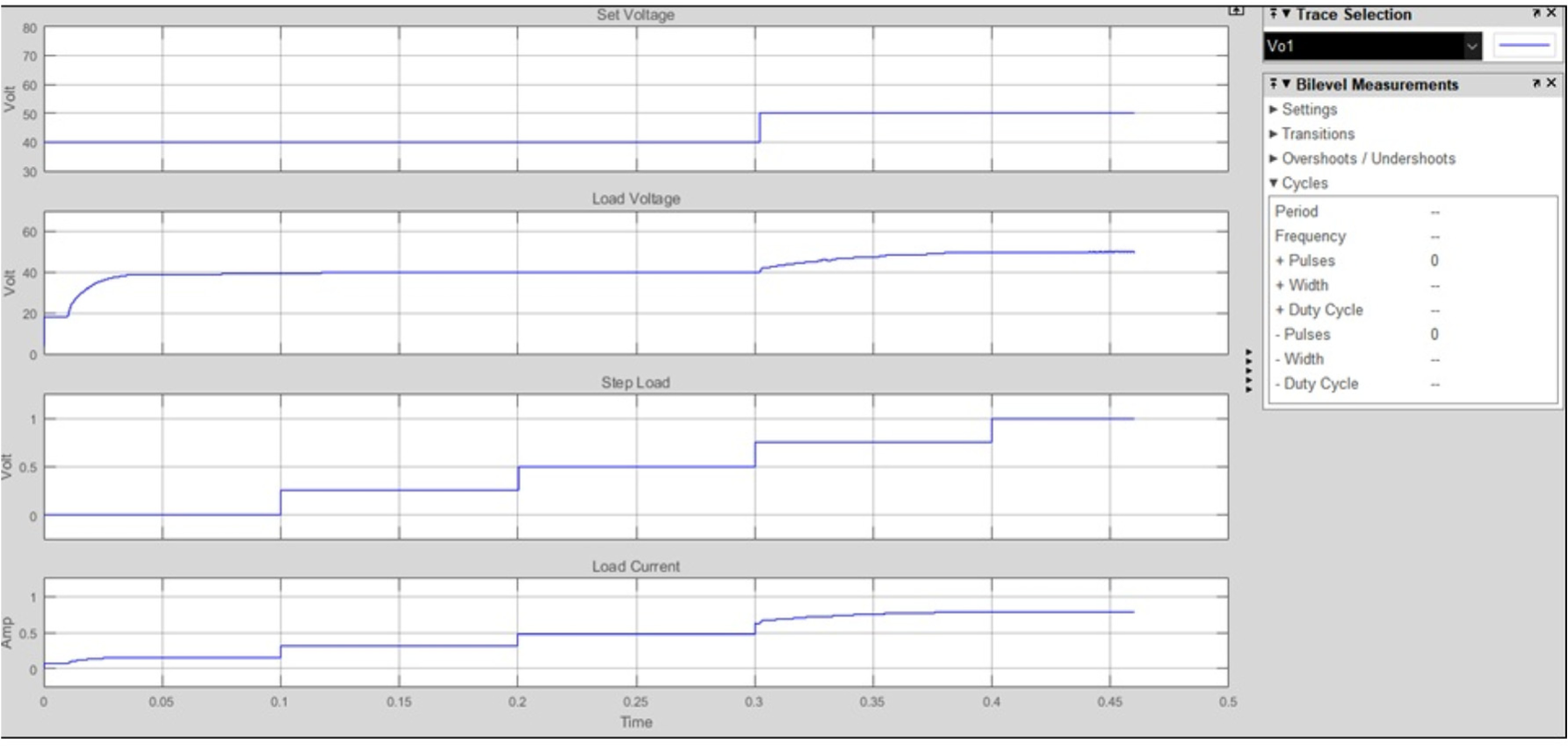
Response of LUO converter in closed-loop operation under load-varying condition.
Response of LUO converter for varying load.
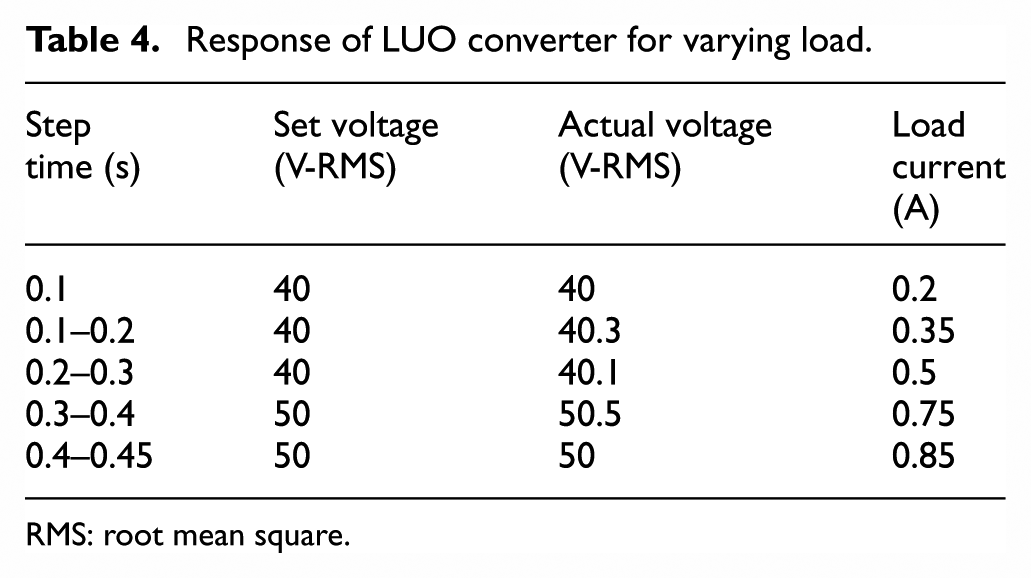
RMS: root mean square.
Simulation of IPT full system control (primary and secondary connected to LED load)
IPT full system control involves both primary side and secondary side control, which is called the voltage control with closed-loop operation for the following combination:
Secondary side voltage is controlled and given to the load;
Secondary side voltage is controlled and given to the battery.
Secondary side voltage closed-loop control for load is involved under the following conditions:
Inverter set voltage: 30 V (RMS)
Primary side coil voltage: 30.2 V (RMS)
Converter set voltage: 50–50.5 V (load voltage)
Figure 12 deals with the closed-loop response of both primary side inverter and secondary side LUO converter due to the maximum peak overshoot of around 9 V in the inverter output; the converter output takes more time to reach its settling time as per the set value in the closed loop.
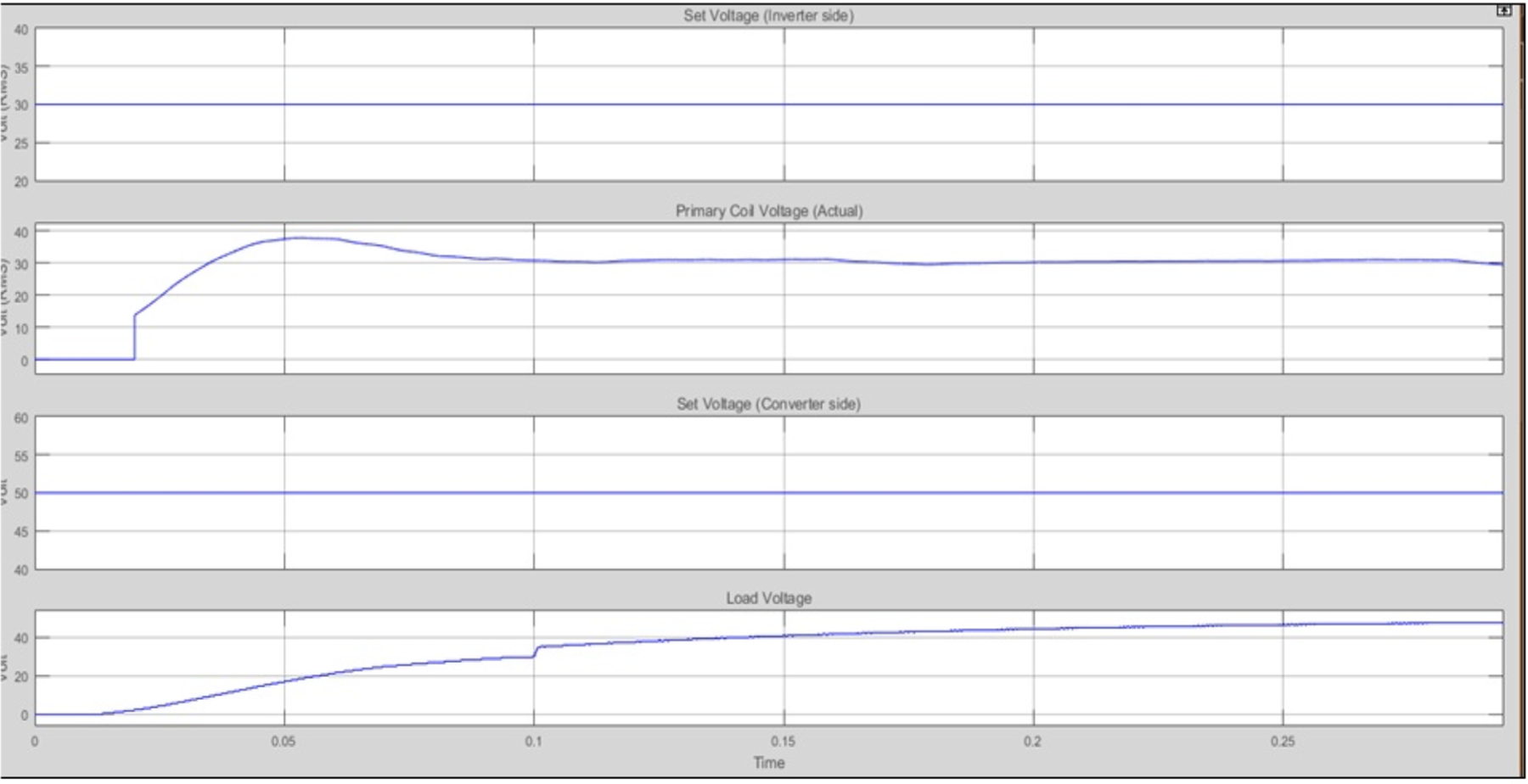
IPT system waveform—inverter to load.
Figure 13 shows the graph between the battery charging current and the inverter output relation. As the inverter provides the required power supply for the battery, the battery gets charged. At the time of 0.14 s, the inverter supply settles at the voltage of 30 V to charge the 24-V battery; it is clearly given that charging at 0.14 s varies the battery charging current from 0 to 0.5 A.
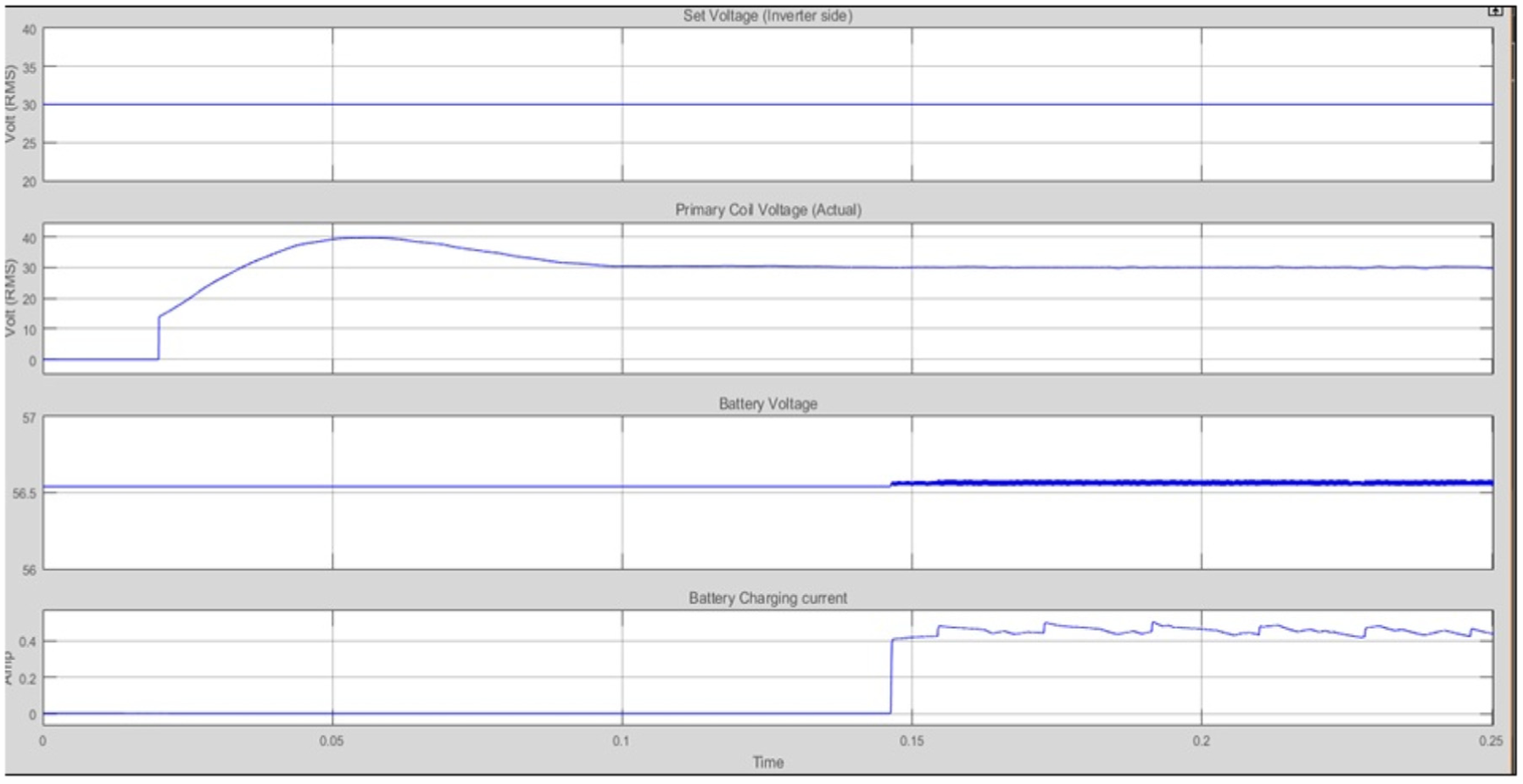
IPT system waveform—inverter to battery.
Simulation of IPT full system control (primary and secondary connected to battery)
Secondary side voltage closed-loop control for battery is involved under the following conditions:
Inverter set voltage: 30 V (RMS)
Primary side coil voltage: 30.2 V (RMS)
Battery voltage: 56.8 V
Battery charging current: 0.5 A
Transition of inverter to load and battery is shown in Figure 14 with pulse width modulation (PWM) variation applied to the converter. Already a changeover switch for transition from load to battery is shown in the simulation circuit of secondary side control with LUO converter: in that if the switch is in ON (1) position, the PI controller will be ON and the LUO converter enabled, and the converter output is applied to the load. Similarly, if the switch is in OFF (0) position, the charging controller11–13 will be ON and the LUO converter enabled, and the converter output is applied to the battery. This waveform will clearly explain the variation of duty cycle and the importance of secondary side control by the LUO converter, where battery charging14,15 can be done with high duty ratio when compared to the inverter connected to the LED load.
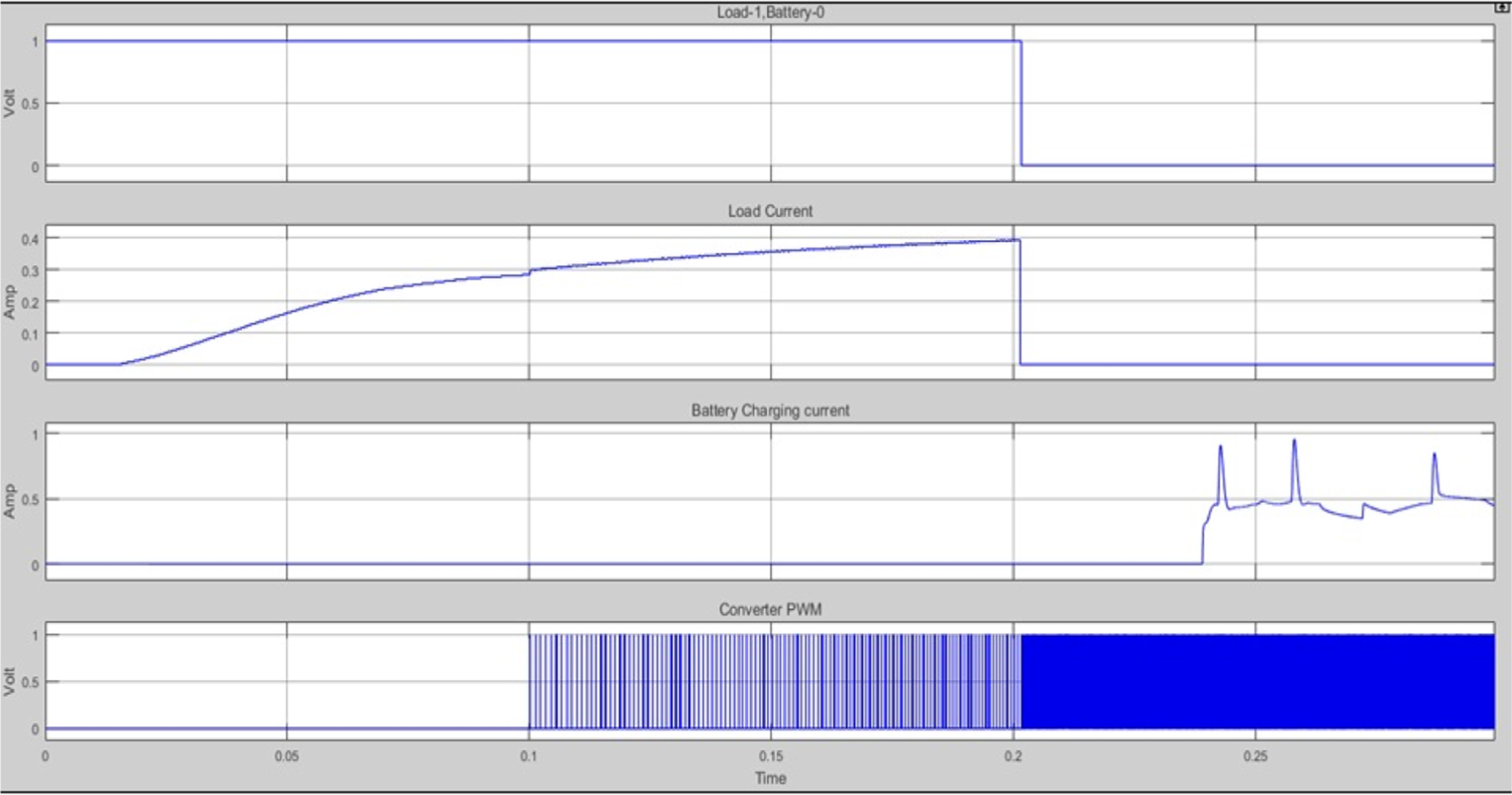
IPT system waveform—transition from load to battery.
Hardware circuit results and its discussion on IPT system
Complete hardware image of the LUO converter–based IPT system is shown in Figure 15. Each and every working part of the system is shown in the figure.
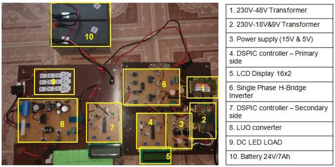
Hardware image of the IPT system.
Figure 16 shows the transmitting and receiving coils of the IPT system. These coils have a resistance of 0.5 Ω, inductance of 256 μH, and it is powered up with a frequency between 5 and 50 kHz. These two coils are kept at two different distances, such as 5 and 7 cm, and the various outputs are obtained between them. From these results, different outputs suggested that as the distance increases, the secondary side output decreases.
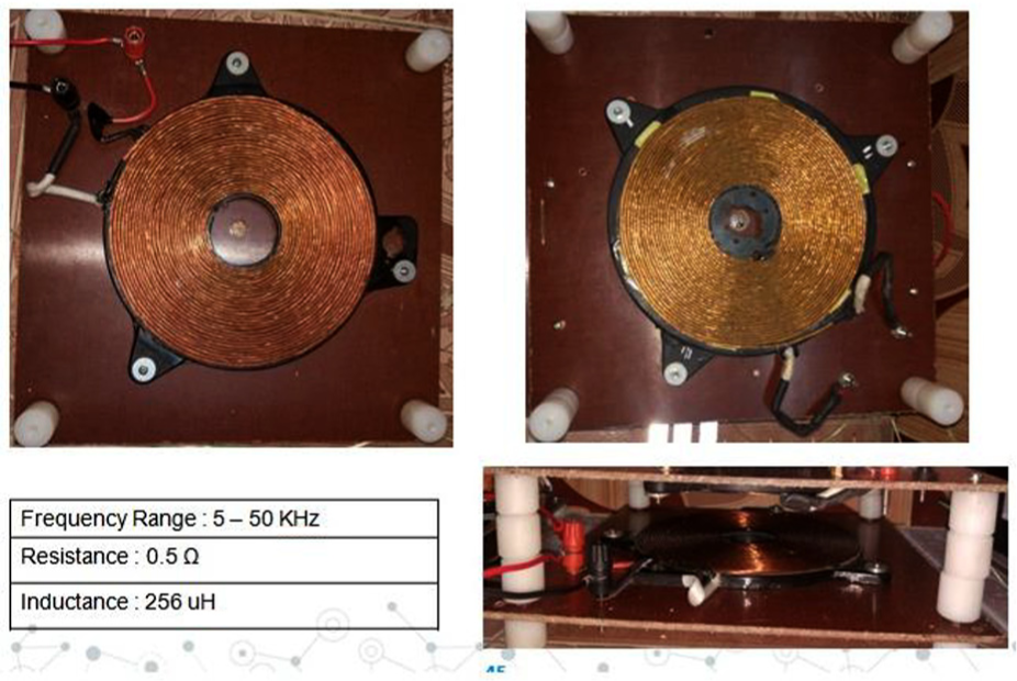
Hardware image of the transmitting and receiving coils.
Figure 17 shows the losses between the transmitting and the receiving coils in the IPT transmitting method of wireless transmission. It shows that the primary coil voltage reduced from 38 to 18 V in the secondary side due to the losses that occurred in the air gap (due to reduced coefficient of coupling) between the primary and the secondary coils; this voltage may be sufficient to drive the LED load, but it is insufficient to charge the 24 V battery. So, a DC-DC converter (LUO converter) is required to boost the voltage to charge the battery.
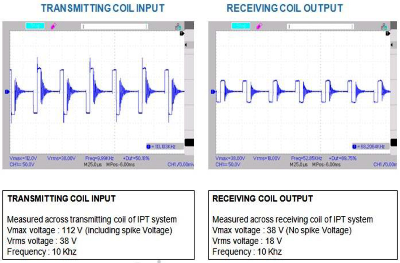
Hardware results: primary and secondary sides.
Secondary side of the coil output is tested with two different distance, 5 and 7 cm, which is displayed in Figure 18. When we vary the distance between the primary and the secondary coils, the voltage supplied to the load will be varied to maintain a constant voltage across the load.
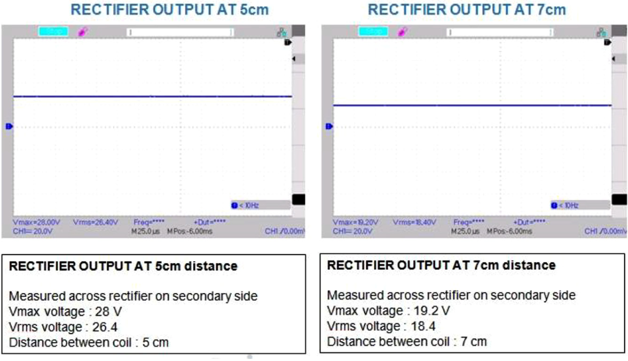
Hardware results: rectifier output for different distance between coils.
Figure 19 clearly insists the importance of LUO converter in the secondary side of the IPT system even for a distance of 7 cm between the primary and the secondary coils. LUO converter 9 provides the required voltage to charge the 24-V battery. To charge the battery, we should apply a slightly higher voltage than the battery-rated voltage.
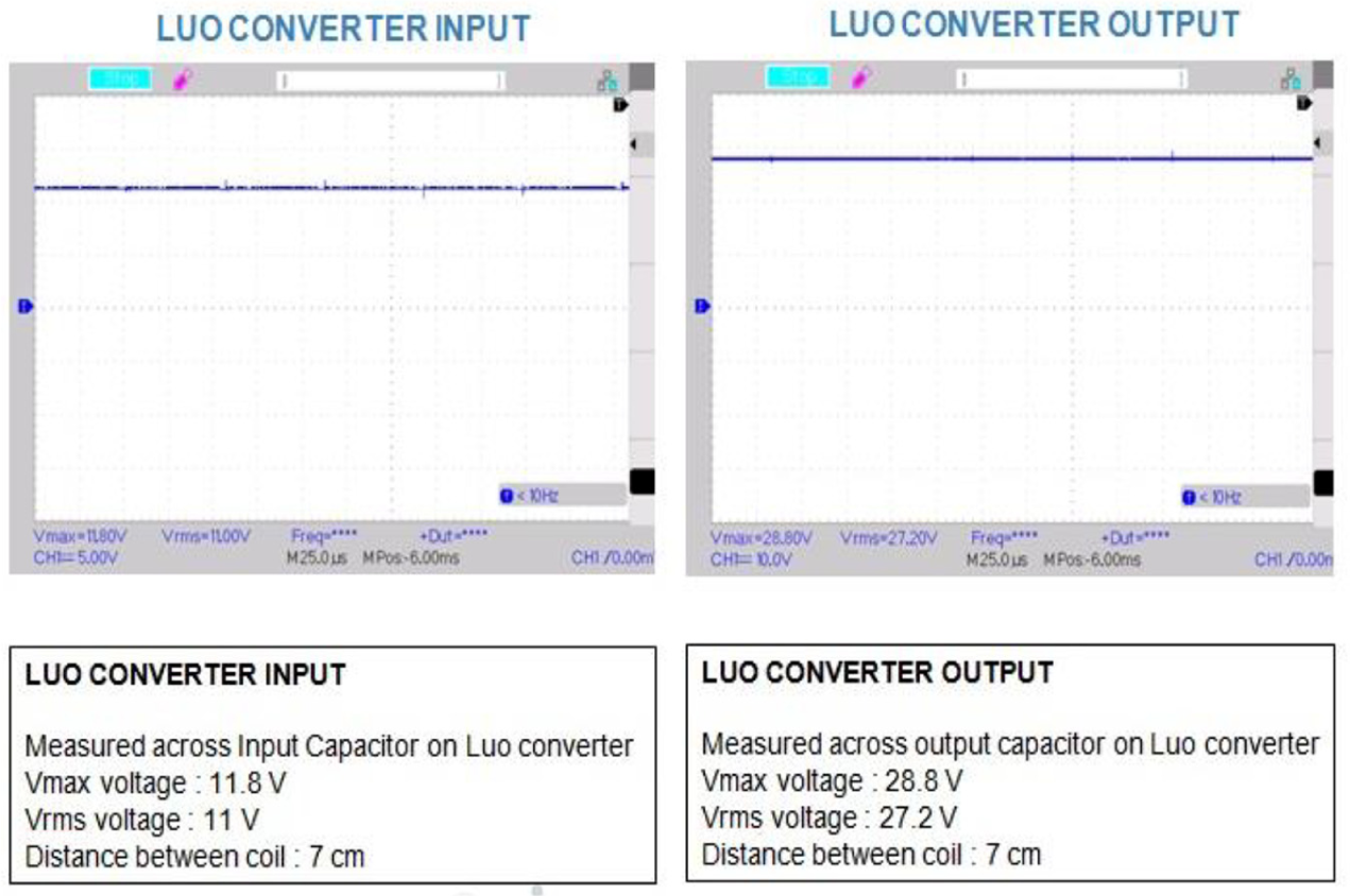
Hardware results: secondary side.
Figure 20 clearly indicates that with very less duty ratio (6.26%) of the LUO converter for a distance of 7 cm between the primary and the secondary coils, the required charging voltage for the battery is achieved. Therefore, stress on the switch is also less as the duty ratio is less.16–18
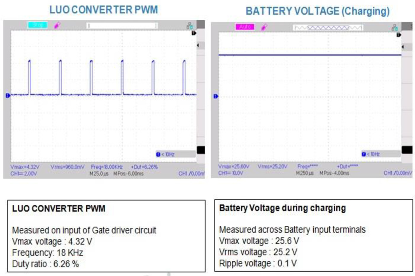
Hardware results: LUO converter with PWM and battery charging.
Results and discussion on laboratory-level investigation of wireless power transformation using integrated laser photon beam
From the hardware results and discussion on IPT, it is clearly understood that wireless transmission by IPT suffered huge power loss. Therefore, laser method transmission has to be implemented and its results also to be compared. Therefore, instead of IPT, DC-DC converter–based wireless power transformation using integrated laser photon beam is implemented. The merit behind the laser power transmission method is that laser beam can travel long distance without much loss. And using integrated laser system, we can transfer more power from one place to another. When compared to more focused laser photon beam, the scattered or broadened laser photon is very useful to get more power output from the solar cells. Laser beam photons are not much affected by environmental gas and pollution when compared to ordinary light photons. This laser beam photon–based wireless power transformation concept is very useful for19,20 solar power plant, windmill, and other related free energy transformation from one place to very long distances.
Figure 21 shows that the two-pointed laser beam is focused on the solar cell to test the losses and transmission efficiency under various operating conditions; here, the transmitter will be the laser light source and the receiver will be the solar panel which is kept inside the EV.
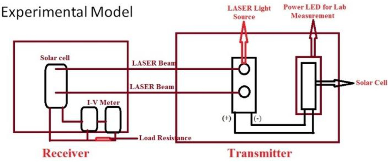
Block diagram of the experimental setup of laser optic battery charging method.
Figure 22(a) shows the hardware image of the laser optic–based wireless power transmission setup. Here, two meters are connected with the receiver solar panel to measure the transferred voltage and current by laser optic method.
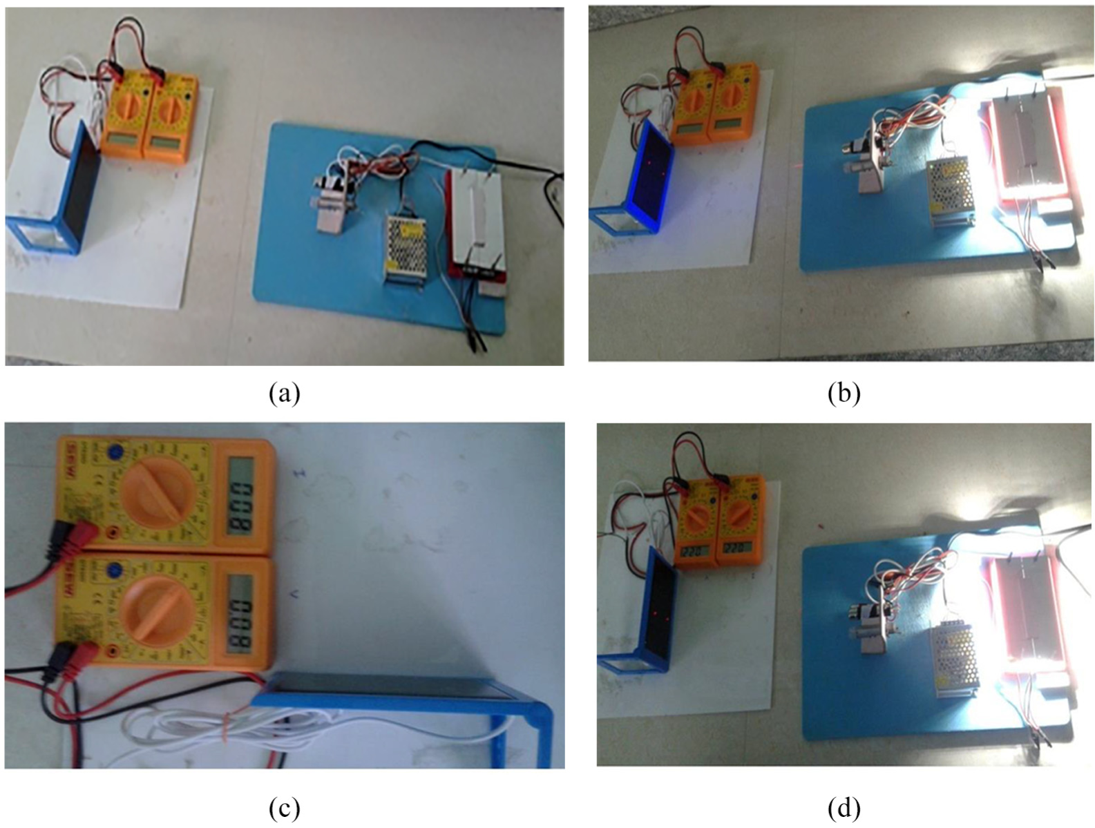
Hardware image of the laser optic–based wireless power transmission setup: (a) fabricated instrument model, (b) fabricated instrument model under laser light shining, (c) current–voltage output without laser beam photon shining, and (d) laser light photon shining area on solar cell: 0.2–0.3 cm2.
The fabricated instrument model is tested in indoor condition without any external solar radiation falling on the receiver solar panel, which is shown in Figure 22(b). Figure 22(c) clearly indicates the received current and voltage levels in the receiver solar panel without the laser optic energy.
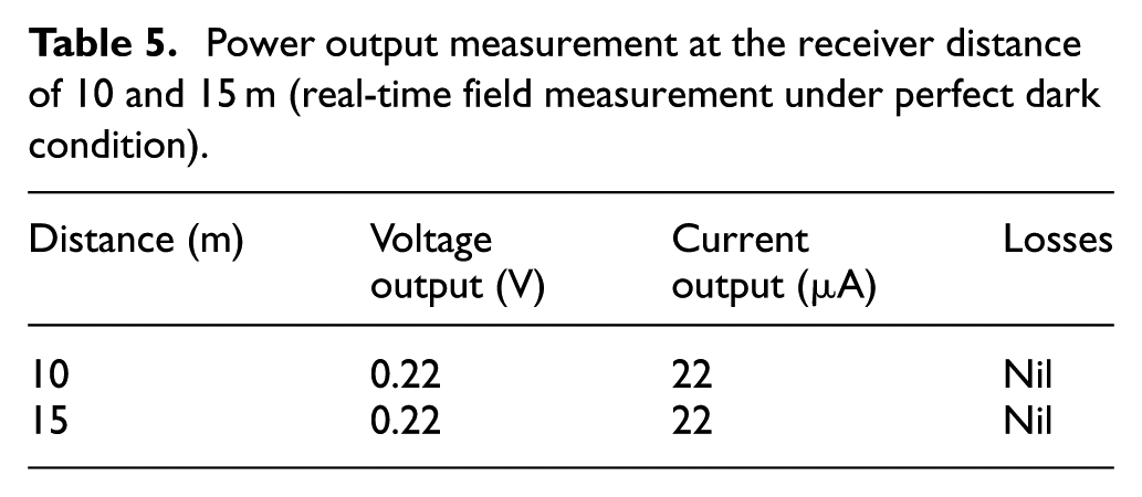
Along with Table 5, Figure 22(d) shows the received current and voltage levels in the receiver solar panel with the two-pointed laser optic energy on the receiver solar cell with the focused area of 0.2–0.3 cm2.
Power output measurement at the receiver distance of 10 and 15 m (real-time field measurement under perfect dark condition).
Conclusion
From this work, it is observed that to achieve safe and optimized losses during wireless power transmission for EV battery charging, LUO converter–based laser optic method of power transmission is better than the IPT method of power transmission under various ground clearance and various ratings of the EV battery, which is observed by varying the distance between the transmitter and the receiver of the laser optic transmission method. The power transmission method is implemented in the hardware, and the losses are found accordingly. The laser optic method helps to achieve maximum efficiency and maximum energy utilization than the conventional system. Analysis of the experimental results is done to show that the proposed system can be successfully implemented in the emerging EV applications.
Footnotes
Declaration of conflicting interests
The author(s) declared no potential conflicts of interest with respect to the research, authorship, and/or publication of this article.
Funding
The author(s) received no financial support for the research, authorship, and/or publication of this article.