
Abstract
This study presents designing and evaluating a reliable wireless power transfer (WPT) mechanism to charge electric vehicle (EV) batteries using resonant coupling. The EV wireless system was created applying the principles of mutual inductance whereby the receiving and transmitting coils were interlinked and connected to their circuits. Significant mathematical work was also done to obtain the equations for the impedance, the power input, and output power. Proteus software was employed to draw a Printed Circuit Board (PCB) for the reception of the receiver and the transmitter circuits. The simulations were conducted using ANSYS Maxwell and MATLAB softwares, utilizing the key parameters of the transmitter and the receiver coils. The experimental setup included an EV installed with transmitter and receiver circuits, copper coils, a compensation network of capacitors, and a 12 V battery voltage monitor. The study showed that the efficiency of wireless power transfer was 78% with the enhanced power density for the gap ranging between 6 and 20 cm. The innovations presented in this paper are a new lower operating frequency of 70 kHz, coil optimization, and a dynamic study on coil misalignment all of which enhance the efficiency and reduce cost of the proposed system.
Keywords
Introduction
Inspired from Tesla’s ideas from the late 1890s, wireless power transfer (WPT) has seen significant growth over the years. 1 Modern Electric Vehicles (EVs) are a way better option for the traditional underlying fossil fuel vehicles as they considerably emit fewer greenhouse gases. In 2018, greenhouse gas emissions from the transportation sector constituted roughly 28% of total American emissions on the United States Environmental Protection Agency. 2 More specifically, light-duty vehicles were responsible for 69% of CO2 emissions while medium and heavy-duty Vehicles were responsible for 23% of them. 3 Likewise, in the European region, 25% of all greenhouse emissions were reported to result from transport in the same year. Mitigating these environmental concerns, EVs have been developed as a solution to these issues.
The indications are to reduce the greenhouse effect and depletion of fossil fuels, which have promoted the consumption of EVs. WPT is one of the revolutionary technologies that can be used to charge the electric vehicle and has more benefits than the plug-in systems like ease of charging, connectors durability, and user satisfaction. 4 However, the application of WPT for EVs has several significant issues to overcome to provide sustainable solutions to charge EVs.
One of the biggest drawbacks of WPT for EVs is efficiency, especially in light of coil misalignment and potential variations in the separation distance between transmitting (TX) and receiving (RX) coils. In previous works, 5 it was shown that these aspects have a great influence on the coupling coefficient and, therefore, on the efficiency of the WPT system. While several solutions currently exist, including coil designs and compensation networks, these solutions are usually accompanied by additional system complexity, higher costs, and potentially reduced reliability.
Another factor is the cost of implementing WPT systems to ascertain if the costs are affordable for end users. Some of the currently used designs 6 tend to work at high frequencies such as 100 kHz which is good for the efficiency of the transfer power but results in increased cost of the component and complications as well. This trade-off between efficiency and cost has kept WPT systems out of most EVs, particularly in the volume market.
Moreover, the opportunity for dynamic charging of electric vehicles, that is the possibility of charging the car while it is moving, is still to a great extent uninvestigated. Whilst, some earliest work 7 considers the possibility of dynamic WPT systems and highlights the need and problem for the elaboration of sufficiently robust and safe dynamic charging for EVs.
However, the issues of efficiency and power density of WPT systems remain the major concerns that have to be solved if WPT systems are to become mainstream for EV use. That is why, several ideal solutions are presented in this paper for the design of the WPT system for deep-cycle lithium-ion batteries of the EVs adapted to resonant inductive coupling. These innovations include:
Lower operating frequency: Unlike the conventional systems that employ comparatively higher frequencies, for instance, of the range of 100 kHz, the current design is implemented using a relatively lower frequency, approximately, 70 kHz thereby resulting in higher efficacy in power coupling accompanied by relatively cheaper and less complicated system design. This approach solves the problem of the efficiency-cost trade-off in WPT systems directly.
Optimized coil design: This paper presents a new design of an optimized coil with a radius of 13 cm and 3 layers of 18-gauge copper wire which provides maximum power transfer and minimum size of the coil. This innovation helps in making the system efficient to be used in practice and functional at the same time.
Dynamic analysis of coil misalignment: The research examines how coil misalignment and distance can affect the system’s efficiency, which is essential when implementing WPT systems in the real world. Thus, the solutions proposed in the paper can help to eliminate this flaw and improve the efficiency of the existing wireless charging techniques.
This research involves the techniques of designing transmitting and receiving coils to work effectively on resonant inductive coupling or magnetic resonant coupling, compensation circuits to improve the efficiency of power transfer, as well as mathematical models representing the system and its performance analysis. Moreover, a simulation of the proposed system is executed in ANSYS Maxwell and MATLAB and it established an experimental verification of transfer efficiency of about 78% with power density enhancement.
In this paper, a detailed outlook of the WPT system for EVs has been analyzed and discussed. Section “Literature review” provides an overview of various WPT technologies that are currently available in the literature concerning inductive coupling used in EVs. Section “System design and methodology” describes the research method accompanied by the transmitting and receiving coil design. Section “Simulation studies” includes simulation studies done with ANSYS Maxwell and MATLAB. In section “Experimental setup and results,” the authors present how the experiment was conducted and the findings of the experimental results. Section “Future work and recommendations” presents the research limitations and future research directions. This paper concludes with a summary of the conclusion arrived at and its relevance to the analysis of EV charging systems.
Literature review
WPT technology transmits electrical power through different connectionless modes such as capacitive coupling, inductive coupling, and resonant inductive coupling. Among these, resonance inductive coupling is quite suitable to apply to EVs because of the efficiency of the method and the ability to transfer electrical energy over considerable distances. Coil alignment, separation distance, and compensation network have been analyzed, and it reveals that improving all these parameters has a desirable effect on the WPT system’s performance.
WPT system efficiency depends on the correct alignment and distance between the TX and RX coils. These two factors affect the coupling coefficient (K), which represents the magnetic connection between the coils and is a significant consideration when evaluating the efficiency of the system. Coil alignment is defined here as the relative orientation of the TX and RX coils along the coils’ common longitudinal axis. In the best circumstances, the coils are in the same plane, possessing coincident, parallel axes that put quantities like the inductance and the coupling coefficient at their highest. Lateral displacement of the coils or angular deviation decreases the possibility of flux linkage and negatively impacts efficiency because less magnetic energy can be transmitted from the TX to the RX coil. To minimize the effect of misalignments, some types of coils possess more complex geometry or control algorithms that allow changing a system’s parameters to optimize its work under various alignment conditions.
The distance between the TX and RX coils is also another important factor that determines the efficiency of the WPT systems. When the distance is extended, the resulting magnetic field at the RX coil becomes weaker and thus energy transfer and efficiency are relatively lower. The effect of distance on efficiency is not directly proportional; small changes in distance have a massive effect on decreasing total efficiency. For better system performance, there is always a need to develop coils that provide good magnetic coupling even though at larger separations. Some of the parameters that can be adjusted include the dimensions of the coil, its geometry, and the number of turns.
Subsequent research has therefore extended knowledge of WPT systems, especially for EVs. For instance, in Wang et al., 5 the author offered a general perspective on megahertz WPT where materials were presented that compared operating frequency with efficiency and system integration. Furthermore, in Zhou et al. 6 the author analyzed and experimentally demonstrated 2-coil WPT systems and highlighted the role of coil configuration and compensation circuitry in enhancing power transfer efficiency. However, in Gomathi et al., 7 the study focused on the real-world application of WPT along with the Internet of Things (IoT) to demonstrate a more effective approach to the management of EV charging systems.
Inductive coupling works by transmitting energy using two coaxial coils which act as transmitter and receiver, creating thereby a magnetic field. This method involves mutual induction where an AC supply to the transmitter coil creates a magnetic field that in turn produces an output current to a receiver coil. The coupling efficiency is thus dependent on the size, shape, alignment, varied turns of the coil, and the compensation network. Various research studies have shown that enhancing the components of the above list can greatly enhance the power transfer efficiency and the system’s performance.
Current WPT systems for EVs also differ in the design, frequency, and efficiency of the system. Systems that work at higher frequencies (for instance 100 kHz) may achieve efficiencies of up to 75% but their components are often expensive and complex. Indeed, lower frequency systems such as 70 kHz can lead to equivalent or better efficiency using less complex and cheaper solutions. Leading vendors in this field are Qualcomm, WiTricity, BMW, and Daimler which have significantly embraced the innovative technology.
Another application of WPT is dynamic charging where the charging of the EV will take place while the vehicle is in operation; this makes WPT for EVs a valuable future technology in improving the mobility of automobiles. A number of the latest works describe the possible opportunities to help different types of EVs in varied urban and highway situations and make battery design for public transportation easier to create for vehicles in hilly terrain. In Amjad et al. 8 the authors provided an extensive literature review of wireless charging systems for electric vehicles and various forms of dynamic charging and the possible advantages and disadvantages given the wide usage of these technologies. These works provide a literature base for the present research, focusing on enhancing the feasibility and effectiveness of WPT systems for EVs through coil development and system enhancement.
The combination of wireless charging technology in electric vehicles is beneficial in the following ways: The first advantage is the automatic nature of the system, making it possible for the car to control the direction instead of requiring the driver to do it. This feature helps to emphasize the inclusion of EVs for carrying out vehicle-to-grid (V2G) operations especially where the owner is concerned regarding charging at a particular time yet they are not around. The impact of integrated charging schemes on the user experience can be further improved by creating application programs that will enable users to set up their charging preferences and timetables. Also, wireless chargers offer a safer way of charging mobile devices than conductive charging, which heavily relies on an electrical current flowing through cables, and the existence of which is dangerous, particularly in extreme weather conditions of snowing or raining. Wireless chargers do not expose the element to that risk since it does not include conductors in their form. To improve human safety, it is required to maintain and regulate the electric or magnetic fields generated by the transmitter or receiver coils at safe levels. 9
Wireless charging also comes with the possibility to be dynamic or referred to as on-demand charging. Requirements of an EV can be met in other circumstances besides static charging when the car is parked; the technology of charging does not involve physical contact between receivers with their power supply. 10 This includes incidents that can happen within the shortest time say while waiting at a traffic signal or even whilst driving. As the number of chargers in contact with road segments is increased, recharging can be done more often when traveling, and this allows the integration of cheaper, lighter batteries into the design.
Conventional charging systems are not so much publicized mainly because of their high costs and high maintenance which is usually very expensive. Fast charging pod has been designed to support quicker battery charging as an application of wireless charging for EV batteries. Translation of such systems requires directive topologies, compensation networks, coil designs, and energy communication strategies.
Based on these investigations, the idea to use an entire track consisting of charging lines appeared. Case studies show that in Sweden it was possible to build a 6 km-long highway that had a wireless energy charging dock; this may charge the power of a bus through inductive power transfer. 11 Wireless chargers are similar to AC chargers since they add the number of ways the EV can be charged without necessarily requiring a cable. This makes it possible to charge during these short interruptions or even when driving which may mean that the capacities needed from batteries may be nudged down. This article demonstrates the transmission of power using inductive coupling, another technique of wireless power transfer where high power is transmitted via a magnetic field across an air gap between the transmitter coil and chassis of an electric vehicle. 12
Charging station design plays a crucial role in overcoming the many challenges associated with inductive charging systems, including attaining resonance frequency, system division, coil misalignment, coil shape, and air gap issues. Further investigation has shown that several external factors must be taken into consideration, such as transient data such as voltage, current, weather, as well as batteries, charging stations, and hardware design topologies.
The fundamental design of an inductive power transfer (IPT) based wireless charging system for electric vehicles operating at a high frequency of 70 kHz is shown in the block diagram in Figure 1. The input’s AC voltage is reduced by a transformer to 24 V AC, which is then rectified into DC voltage via a separate circuit.

Block diagram of an EV’s wireless charging system.
After being converted from AC to DC, the DC voltage is sent to a bank of compensating capacitors to limit losses. The rectified voltage is then carried by the gearbox coil. A rectifier and secondary compensating capacitors are used to transfer the transmitted power to the DC load, such as a battery, after being gathered by the receiving coil on the receiving end.
A study was done to look at the use of a power system called DC OLEV (On-Line Electric Vehicle), which is intended to lower peak power and power losses as well as perhaps lower substation energy costs. Researchers evaluated the proposed approach to measure power consumption, battery level, and power losses using computer simulations under various conditions. 13 Often referred to as IPT systems with small widths, dynamic and static charging systems are the two primary IPT charging methodologies. Reviews of both approaches have detailed in depth the installation of wireless structures utilizing ferrite forms.
There are two modes of operation for wireless charging: dynamic and static. Static wireless power transfer occurs when an electric car is parked with its motor off, allowing for a full charge. This mode is often seen in parking lots, both public and private, where advanced features may be used to reduce coil misalignments. Static WPT is similar to classic conductive charging in terms of time and infrastructure needs. 14
A few advantages of wireless charging include more charging flexibility and the ability to charge at rest breaks or while traveling. To accomplish effective deployment, we need to overcome both the technical and practical challenges. If these challenges can be overcome, electric vehicle charging may undergo a dramatic transformation, becoming much more accessible and convenient while decreasing reliance on traditional conductive charging methods.
A wide range of technologies, each tailored to a particular need, are involved in wireless power charging. The most advanced WPT technology for electric vehicles uses two air-core coils and is induction-based. As stated in Ampère’s Law, 15 a magnetic field is generated when the primary (transmission) coil produces a current that varies with time. A voltage may be produced when some of this flux combines in a secondary coil, which is also called a receiver. Achieving power transmission is as simple as connecting the secondary coil to the battery electrically.
The amount of power that the secondary coil can generate is dependent on its capacity to absorb magnetic flux, as stated in Faraday’s Law. In this setup, the main current and the positioning of the sending and receiving coils affect the magnetic fields. EV wireless chargers primarily use two techniques – improved coil design and capacitive compensation networks – to enhance magnetic flux over the secondary coil.
Electric car inductive WPT systems often use resonant systems. Resonant WPT uses reactive networks on both the main and secondary sides of the electrical system – compensation networks – to function at resonance. 16 A connection is made between the capacitors and the primary and secondary coils. The primary and secondary coil connections – whether they be parallel, series, series-parallel, or parallel-parallel – must be addressed first. The effectiveness of resonant wireless chargers relies on coils, compensation networks, and power converters.
Capacitive wireless power transmission can overcome metal barriers because of the very small losses. Capacitive WPT is made possible because the electric field is contained inside the gap between the two plates of the capacitor. Induced current generates an electric field in the receiver, much as in resonant WPT, when the coils are close together. The capacitors are linked to the lithium-ion battery to compensate for energy transfer losses, so all of the electric power from the charging current is conveyed. 17
When it comes to charging lithium-ion electric cars, wireless power transfer offers certain benefits. By ensuring that electromagnetic emissions are kept out of potentially dangerous areas, security is enhanced by first restricting the electric field to the area between the coils. Wireless chargers with capacitive compensations are smaller and less expensive than resonant chargers. Additionally, Litz wire coils lower high-frequency losses.
The study is focused on the static charging apparatus. Lithium-ion batteries are preferred because of their many advantages, including reduced prices, rapid and continuous wireless charging and discharging, high recharge cycles, accurate voltage-based state-of-charge (SOC) detection, low leakage current, and lightweight design.
Talele et al. 18 experimented with the integration of composite phase change materials (PCMs) in preventing the occurrence of thermal runaway in lithium-ion batteries. From their experiments, they concluded that PCM integration can enhance battery safety and reliability through better thermal regulation.
Tran et al. 19 conducted a comparative study of equivalent circuit models for four common lithium-ion battery chemistries: LFP, NMC, LMO, and NCA. The work of the authors is very helpful in understanding how various battery types perform under different operating conditions, which is important in making a WPT system to suit a particular chemical type of battery. Likewise Bais et al., 20 made a comparative analysis of the thermal performance of novel phase change material and nano-enhanced phase change material used for passive battery thermal management in lithium-ion batteries with high C rate discharge. The experiments showed that their proposed modifications were effective for managing heat, and improving the WPT systems’ reliability and safety for the EVs.
Furthermore, Pu et al. 21 specifically aimed at the enhancement of the physique of a serpentine–channel cold plate for lithium-ion batteries’ thermal control through the consideration of the field synergy principle. Their work offers guidelines on how better thermal systems could be designed, and incorporated in the WPT-equipped EVs.
Finally, Chen et al. 22 suggested one adopt sequence training and data shuffling methods to improve the performance of the recurrent neural network-based battery voltage models. Their work could be instrumental in helping accurate and reliable predictions of battery performance crucial in improving WPT systems, safety and lifespan of the EV batteries.
Industries like transportation are using wireless power transmissions more and more in an attempt to optimize their efficiency. Several technology approaches are being used to boost productivity and efficiency. 23 These sectors include photovoltaic systems, wind-powered hydrogen filling stations, tidal power, and optimized wireless power transfer for vehicles.
Sun et al.’s extensive study delves into the latest developments in WPT methods, including examining their use in electric vehicle applications, the distinctions between static and dynamic charging, and different coil topologies. 24
A prototype that generated 2.2 kW was created by Nan Liu using Litz wire coils with a diameter of 40 cm. Automatically adjusting to peak efficiency and shifting to the resonant frequency was made possible by a feedback circuit-based variable-frequency control method. 25 This approach included features like load-specific frequency selection and variable-frequency control. The primary LC circuit’s frequency should be kept constant and the effects of air gaps and coil misalignment were mitigated with the help of an additional inductor. Figure 2 shows schematics of several WPT systems that are resonant.

Resonant WPT system’s schematic. 9
The circuit contains self-inductances (L1, L2) for the two coils, mutual inductance (M) between them, and copper losses (r1, r2) for the coils. Iron losses are ignored since the coils are air-cored. The series-compensated capacitors (C1 and C2) link the transmitting and receiving coils. The circuit additionally considers the internal resistance (RC1, RC2) of the capacitors, the impedance (r
p
) of the load resistance (RL), and a high-frequency AC power source. The source and load side resistances


These are obtained from the resistances of the coils and the coefficient of mutual inductance between them. The capacitances


Conversely, RS1 and RS2 are formed by combining the source and load side resistances. Based on these calculations, we may conclude that both coils need to operate at resonance frequency to transmit the maximum amount of power.

The aforementioned parameter was determined from the setup WPT system. RS1, RS2, rp, and RL are static, and by analyzing Kirchhoff’s law (KVL) in Figure 2, we can determine the relevant values


Where:


On the other hand, the mutual inductance, or M, between the transmitter and receiver coils is expressed as

Similarly, the impedances of these coils are expressed as


Using these impedances, the current through the transmitting coil


The final equation of the power delivered to the load by the receiver coil and the power input drawn by the transmission coil may be represented as:


One can drive the series-compensated inductively coupled system’s overall efficiency with

Equation (17) shows how the efficiency of wireless power transmission is affected by the supply voltage (VS), load resistance (RL), transmitting side current (I1), and receiving side current (I2). Efficiency is directly regulated by the load resistance (R L ) and is favorably affected by the square of the receiving side’s current (I2). However, the supply voltage (VS), the angle between VS and I1, and the current on the transmitting side (I1) all have a detrimental impact. Resonance is essential to a WPT system’s optimal functioning, and for resonance to occur, the resonance frequencies of the transmitting TX and RX sides must coincide. Consequently, the resonance frequency may be written as follows:

Here it is important to note that, during the development of the mathematical models, several assumptions were made for the sake of convenience. Firstly, it is for the ideal components with the parasitic effects which are normally smaller but can contribute largely to the loss of efficiency in real systems. Secondly, the model also assumes a constant operating frequency and hence the variations in the frequencies are known to cause detuning along with reduced efficiency. Moreover, the model does not account for iron losses arising from having air-cored coils, although, if ferrite cores are put in place, these losses should be included and this will contribute to the errors in the model. The analysis also prescribes linearity in the system’s response though non-linearity can occur in the systems components or operation condition to varying degrees. These assumptions have the advantage of making the mathematical modeling more efficient but may not reflect every aspect of the model. Thus, considerable efforts for the future should be directed at improving the model concerning these factors and comparing the theoretical predictions with the experimental data available.
Lithium-ion batteries are not limited to serving as an EV’s power source. The technique of fully charging and discharging batteries during each cycle is referred to as deep-cycle charging. 28 This method is preferable as it enables the battery to function optimally and consistently across several charge and discharge cycles. These batteries are preferred because they have a high energy density, can store and deliver much more energy per unit weight, and have a longer driving range, making them suitable for EV applications. Additionally, they have a stable voltage output throughout their discharging duration, resulting in more consistent performance.
However, the use of lithium-ion batteries is associated with several difficulties. Due to the formation of the solid electrolyte interphase layer within the battery, this technology eventually experiences quality deterioration in the form of a progressive decrease in its charged capacity, which reduces the EV’s driving range. 29 Using lithium and cobalt materials for manufacturing also has environmental and social implications. Moreover, lithium-ion batteries are vulnerable to thermal casualties, such as fires and explosions, due to potential exposure to high temperatures, physical damage, and manufacturing flaws. Several strategies can mitigate these issues, including improved battery chemistries, battery monitoring/management systems, and thermal management. Since these batteries have fixed lifetimes, recycling the materials used in this technology should also be ensured. 30
System design and methodology
The implemented inductive power transfer system encompasses several key components, such as the design of transmitting and receiving coils, a WPT charger, a charging circuit, an energy storage system, and measuring devices to monitor the SOC of the lithium-ion battery. In the following discussion, an attempt will be made to discuss the important parameters that affect the efficiency of a WPT system: Copper coil geometry such as the coil size, shape, number of turns, and configuration of the turns are key factors that determine the efficiency of the WPT system. Increasing the size of coils allows for higher mutual inductance and efficiency due to stronger magnetic fields but at the same time, higher complexity of better alignment of TX and RX coils. The strength of the magnetic field is affected by the number of turns in the coil such that more turns will increase the strength of the magnetic field but also increase the resistance of the coil and hence increase the resistive losses and decrease the efficiency of the transformer. The materials used in the construction of the coils and other parts of the WPT system also play a major role in efficiency parameters. Copper is the most used material for coil winding owing to the high conductivity that reduces resistive loss. Ferrite cores can help in increasing the magnetic flux density thus increasing the coupling coefficient, but there are other losses such as eddy current and hysteresis losses. Some other external factors, such as temperature, humidity, and electromagnetic interference (EMI) also affect the WPT system’s efficiency. At high operating temperatures, there is an increase in resistive losses, if moisture is present then dielectric properties and leakage currents are compromised. EMI can reduce the system efficiency and affect the circuit functionality; protecting and designing the circuit are the keys to improving its functionality in diverse environments.
These components are meticulously developed and seamlessly integrated into an electric vehicle charging station. The WPT Prototype shown in Figure 3 is the integration of key components required in the system for wireless power transfer in an EV. This system includes the charger of WPT, which is the main power supply. The transmitting coil which is located in the WPT charger produces a magnetic field through the supply of an alternating current (AC). The magnetic field of this type is picked up by the receiving coil positioned under the EV which is aimed at aligning with the transmitter to maximize the coupling factor.

EV’s WPT prototype.
The charging circuit in the EV is responsible for the conversion of the received electromagnetic energy into the form that can be used for charging the Energy Storage System (ESS), most commonly a lithium-ion battery. This circuit also includes compensation capacitors for tuning the transmitting as well as the receiving coils. The battery voltage monitor effectively observes the numerical value of the State of Charge (SOC) of the ESS and can report the status of the battery in real-time.
This is where the receiving and transmitting coils on the charging station and the mounted unit on the EV align themselves to allow the power transfer to take place as the vehicle is driven into the charging station. It is self-charging, and the charging process is done automatically, to ensure that once the battery is charged to its maximum, the charging is stopped. The additional features like the alarm and the shutdown options that are provided with the system, make the usage of the system safe and efficient. This comprehensive system facilitates efficient wireless charging, enabling effective power transfer and accurate monitoring of the battery charge status, contributing to the overall effectiveness and reliability of the charging infrastructure.
The workflow in this system begins with an EV being driven into the parking lot, where the charging devices are deployed. Once the EV is in place, the receiving coil within the vehicle receives power from the transmitter, initiating the charging process. Simultaneously, the battery voltage monitor continuously tracks the charge storage, ensuring optimal charging levels. When the battery reaches its full charge, an alarm is triggered, and the charging process is automatically stopped by disconnecting the power source. The corresponding flowchart, shown in Figure 4, visually represents this process.
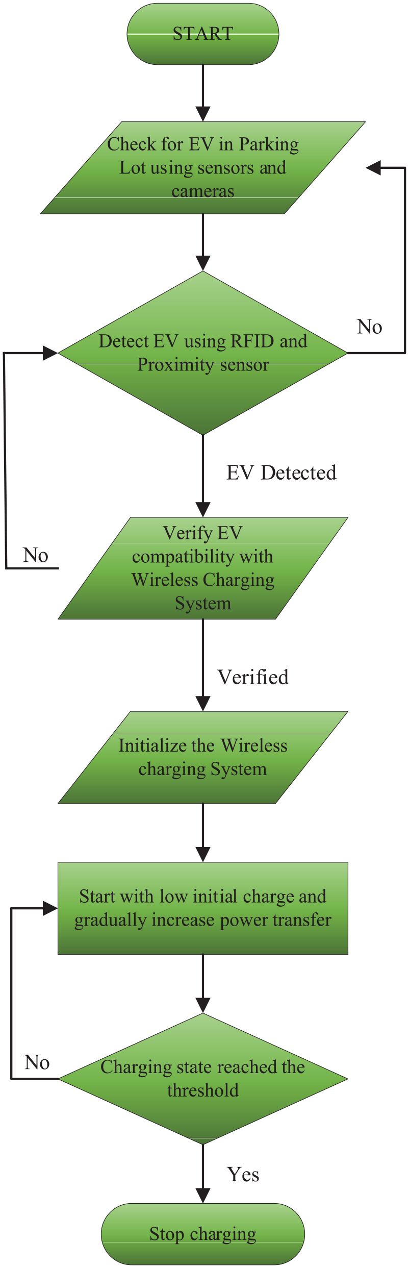
Flowchart of WPT.
Self-inductance (L), mutual inductance (M), coupling coefficient (K), and magnetic flux magnitude (B) are simulation parameters for the transmitting (TX) and receiving coils (RX), which were obtained using ANSYS Maxwell software. MATLAB was adopted to estimate the output power of the proposed system and its efficiency. The test objects include a sample electric vehicle loaded with a wireless power transmission system. The vehicle’s RX coil is placed in a manner that it is connected to a corresponding TX coil, connected to a DC power source with 24 V, 5 A. Compensation is provided in the form of compensation capacitors that are installed on both the TX and the RX sides and should be equal to 12.832 nF.
The AC power received is then rectified to DC before being supplied to the DC-DC regulating circuit to the voltage needed in the EV battery. The DC battery voltage monitor is used for measuring the input and output power. As indicated below in Figure 5.

WPT prototype.
Simulation studies
Proteus circuit
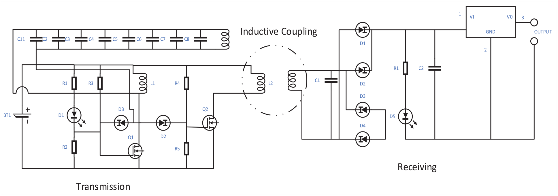
For the design of the electronic circuits, we used proteus software to first identify the simulation values and working of the circuits of both the transmission and receiver sides. Figure 6 illustrates that we are using a fixed voltage source to power up the entire network of devices consisting of capacitors, inductors, resistors, and the capacitor compensation network which transfers power via the coil. However, the coil cannot be drawn here so we have assumed an inductor in its place.

Transmission’s circuit.
Electromagnetic compatibility (EMC) problems and signal integrity difficulties can be solved through careful PCB design. The design is optimized to ensure effective power transfer, reduce power losses, and offer a reliable and compact solution.
Similarly, Figure 7 shows an inductor in place of the receiver coils, followed by a rectifier bridge connected with a single capacitor (instead of attaching parallel capacitors) before the bridge. A voltage regulator is attached, which transfers the power towards the battery (shown as output).

Receiver’s circuit.
ANSYS Maxwell coil designs
Figure 8 depicts the two-coiled model using ANSYS Maxwell for the WPT system. The simulation system uses a separate transmission coil in green and a receiver coil in yellow; these two coils were isolated to measure particular parameters and adjust the system’s performance. The transmission coil is required to produce an oscillating magnetic field; it has been constructed with target inductance and capacitance for resonance and existing power coupling. Technical considerations like turns within a coil, size, and shape of the coil, wire diameter, and the operating frequency were carefully aligned to realize a high magnetic field with moderate loss.
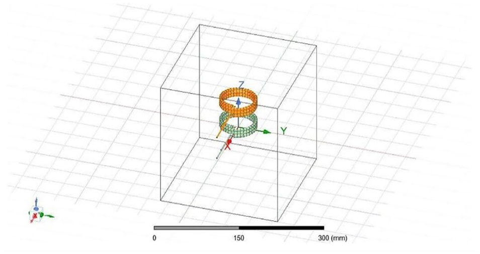
Two coil design on ANSYS Maxwell.
The receiver coil is attached in such a way that it can gather the electromagnetic field generated by the transmission coil and then convert the electromagnetic energy into electrical energy. Like the case of the transmission coil, various attributes of the receiver coil such as turns, dimensions, and thickness of wire used were adjusted with a view of improving transformer efficiency. Concerning the variation in distance, this is a common attribute in wireless charging solutions, thus the simulation was done with distances of 6–20 cm. This range was chosen to study the variations that take place regarding the efficiency of power exchange and the whole system. In the simulation plan between the coils, air was used as the medium because air is influential in terms of coefficient coupling and transmission of power within inductively coupled systems. To ensure that both coils are oscillating at the desired frequency, the inductance and capacitance of the coils were measured individually. Resonance needs to be attained perfectly to achieve good energy transfer in any real-world system. In the case of superconducting coils, the simulation also calculated the magnetic field between them. From the overall field distribution, fine-tuning of the coil turns and the spacing between them can be done to optimize the performance.
The coil designs that have been obtained here from the ANSYS Maxwell are approximations of near-realistic WPT systems. Some of them have been developed with prototype parameters and correct coil spacing, which gives information useful for real WPT experimental systems. Therefore, the understanding of the inductive coupling, resonance, and field distribution achieved through this simulation is extremely helpful for the maximization of energy transfer and the optimization of the operation of relevant applications. The two-coiled model designed in ANSYS Maxwell had close to realistic dimensions and the design was done in a very appropriate manner. The first coil served as the transmitter coil; it was made of copper wire that has the thickness, or gauge, of 18, wound into a cylindrical shape of 13 cm radius and was 3 turns deep. The receiver coil also had the same radius of 13 cm, but three turns of 18-gauged copper wire were used. The reason for using copper wire was because of its low resistance and ability to produce a great amount of magnetic field. The material properties applied in the work for the simulation belong to the basic copper with a conductivity of approximately 8 × 10⁷ S/m and a relative permeability of 1. The distance between the coils varied from 6 to 20 cm since it emphasizes the real situations in the charging of electric vehicle systems. The coils were to be designed to oscillate at a frequency of 70 kHz which is high enough to make the coils efficient, but low enough to be cost-effective and therefore useful in real life.
To achieve a high degree of realism of the proposed approach and its practical applicability, the chosen parameters of the simulation environment corresponded to real operating conditions. The amount of mutual inductance that existed between the transmitter and the receiver coil depended on the configurations of the coils and the material used. The inductance and capacitance of the coils were taken to check the resonant frequency to transfer efficient energy. Another verification of design was done using the magnetic field distribution so that further energy was not lost and maximum energy was transferred to the desired resistance. These parameters were vital to maintaining a real-life standard to avoid or control experimental variations while giving a reliable foundation for the experimentations.
MATLAB
MATLAB was used in the calculations that engaged the implementation of the mathematical model and produced the simulated output power and efficiency of the WPT system. MATLAB Simulink model presented the comprehensive simulation of the WPT system appropriate for EV charging as depicted in Figure 9. The AC power was first converted to DC power by a diode rectifier then the DC was filtered and sent through further. The next action based on the discussed literature included rectifying the obtained DC power and back to high-frequency AC by employing an inverter. This was important in increasing the efficiency of the wireless power transfer since higher frequencies of AC improve the efficiency of the coupling inductor.

MATLAB simulations.
The high-frequency AC was transmitted wirelessly using two coil parts having mutual inductance and capacitive compensation. On the vehicle side again, the received high-frequency AC power was converted into DC for rectification. This rectified DC power was further utilized to charge Li-ion batteries; however, the actual battery model also incorporates attributes including supply voltage, charging current, and SOC to make actual battery charging. Within the context of the model, scopes and measurement blocks were established at different points in the system to observe basic parameters containing voltage, current, power, and SOC determination to assess the efficiency of the features. Further, the model comprised several elements of the DC interconnection as well as the DC filter which was aimed at removing any ripple components from the power taken from the source and supplied to the battery and other loads.
In selecting the parameters of the simulation, it was important for the study to get an environment that closely resembles operations in a real-life setting to get reliable results. Specifically, the input power, current, and voltage were chosen by the situations that are realistic for EV charging. The values of mutual inductance and the coupling coefficient were calculated based on the geometrical characteristics of the coils and the nature of the material between them which makes the model more applicable. The preference of the 18-gauge copper wire for the coils was because the element offers high conductivity in producing a capable magnetic field. As for the frequency of 70 kHz it was important to implement the maximum possible frequency to increase efficiency and, at the same time, choose the frequency that would make the system practicable. These parameters helped in achieving more realistic simulations to reflect the performance of the WPT system as required for the experiments.
This MATLAB Simulink model is very suitable for large-scale research since it accurately describes real-world components and behaviors. Driving characteristics like resistance and inductance from actual measurements ensure realistic performance. The control systems in the model can be implemented on real hardware since they are based on industry standards. The model maximizes both safety and efficiency, hence lowering trial-related risks. The monitoring capabilities allow for a thorough validation against experiment data.
PCB circuits
A final stage PCB schematic was transformed into a working circuit, as shown in Figure 10. The above PCB with copper coils attached to the capacitor bank is the receiver unit, and the bottom coil with the capacitor bank and two heat sinks is the transmission circuit. The receiver is to be attached to our demo electric vehicle, and the transmission unit is to be attached to an acrylic box with a connection to the AC main, depicting the charging pod.

PCB circuits.
Experimental setup and results
For the experimental setup, coils were used with a diameter of 13 cm and having 3 layers of 18-gauge copper wire. The compensation capacitors had a value of 12.832 nF, which was very important in ensuring that resonance was achieved. AC power source to power the 24 V at 5 A was recommended because the source of power is constant thereby making the experimental setup reliable. The charging process in this study followed the constant current (CC) method. CC charging is the closest to the actual charging process of an EV battery and therefore useful to simulate practical charging conditions. It enables a continuous flow of 5 A throughout the charging process which enables one to compare the efficiency and performance of the system continually.
The battery voltage monitor was used for observing the SOC of the battery during various stages of the experiment as part of the setup. During the charging, the output voltage fluctuated, and therefore, the use of the voltage regulator avoided any variations that could influence the results. PCB was designed to decrease losses and the interferences between different parts of the circuit, especially between coils.
The technical requirements of the setup were carefully chosen and strictly adhered to improve the significance of the findings. In this study, the battery cell had a nominal voltage of 12 V and a nominal capacity of 30 Ah. The anode material used was graphite while the cathode material used for the battery was Lithium Nickel Manganese Cobalt Oxide commonly referred to as NMC. The electrolyte in the battery cell was lithium hexafluorophosphate (LiPF6) in a solution of organic carbonates. A digital multimeter and an oscilloscope were utilized to measure the voltages, current, and power in the experiment to obtain proper readings and support the experimental results.
There was also a lot of concern on the orientation of the two coils with careful orientation to ensure maximum coupling was achieved. This was important, especially in realizing the recorded 78% efficiency of the activities. These conditions were also set to resemble real-world conditions possible for an electric vehicle; parameters and components used were also brought to scale, which corresponds more to a full-sized Electric Vehicle instead of its smaller-scale prototype.
The experiment results are described in Table 1. The coupling coefficient (K) value was determined from the ANSYS Maxwell simulation analysis of the double-coiled model. The output power value has been computed using MATLAB simulation based on the implemented mathematical model. This setup was done to mimic a real-life scenario that can support an electric car. The parameters and the parts used were the real size, not for a small electric vehicle prototype but a standard-sized one. The k value is extracted from the ANSYS Maxwell simulation of a double-coiled model, tuned for real EV dimensions and power demand.
Comparison of our technique and the technique used in Elahi et al. 9

The findings of the experiment also showed that when the coil separation distance was kept at 13 cm, the maximum power transfer capability was rated at 78%. The waveform of the output voltage and that of the current was also confirmed to be sinusoidal hence meeting the standard required. When comparing the results with the simulation data, it was easy to conclude that output power as well as the overall system efficiency drops as the distance between the two coils increases because of the increase in the input power needed for power transfer. This dependence on distance underscores the importance of coil positioning to deliver the specified results and efficiency of the wireless charging system.
Table 1 presents the outcomes obtained from experiments and MATLAB simulation experiments in a tabular form. The values in the table prove that the data from the experiment are rather close to the simulated data, which confirms the efficacy of the mathematical model and the overall concept of the system. The information provided by the coils and capacitors was precise to give the experimental results as close as possible to the scenarios faced in real-life applications.
Comparison with existing system
The comparison between the existing technique having said the design of the system was at the 100 kHz operating frequency, ultrafast field effect transistors (MOSFETs) for designing the inverter circuit, size of the radius of the coils (12.05 cm) winded by copper pipe cable with 39 turns of 50 strands. With this, the output power is 100 W with only 75% of efficiency.
Our design introduces a technique that utilizes a relatively low frequency of 70 kHz, in contrast to the previously mentioned system. This lower frequency allows for an impressive power efficiency of up to 78%. The design also incorporates smaller coils with a radius of 13 cm, using 18-gauge copper wire with 3 coil turns. This configuration results in a power output of 90 W. Additionally, by employing commonly available MOSFETs, the inverter circuit becomes more cost-effective. Table 1 provides a comprehensive summary of the key differences and comparisons between the two systems, highlighting the advantages and improvements offered by our proposed design.
The MATLAB simulation was able to pull off many different kinds of outputs in the form of graphs. Figure 11 shown below illustrates the roadside voltages (500 V) and current (20 A) corresponding to the time in sec(s), specifically speaking these are the voltages on the primary side winding that is taking power from the AC mains. The next up ahead is the source voltage and current as in Figure 12. The graphs show the voltage section as a peak of 320 V and the current section as 65 A.

Roadside winding current and voltage.
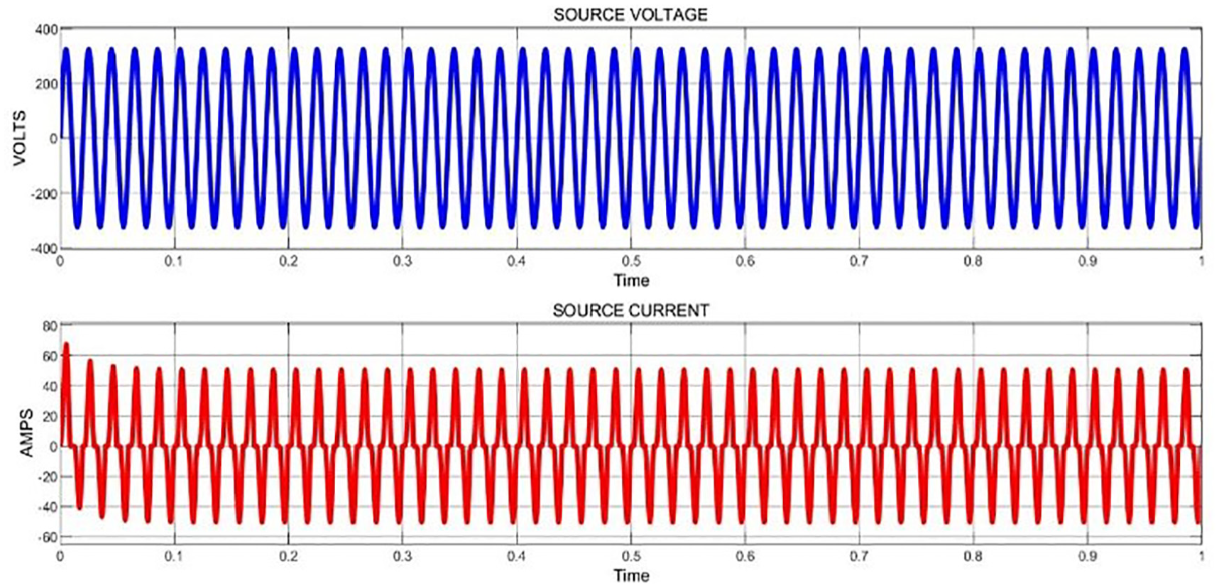
Source current and voltage.
Now as soon the power is transferred onto the receiver coil of the EV this is termed as vehicle side winding voltage and current in Figure 13 shown below. The value we see of the voltage is 400 V and the current value is shown at about 25 A.
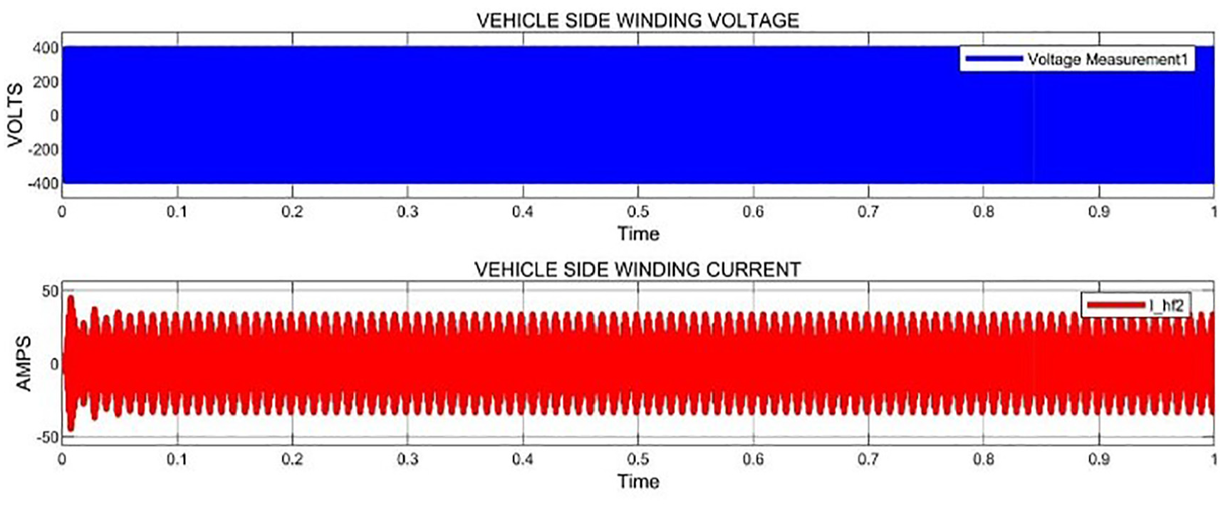
Vehicle side’s winding current and voltage.
Lastly, Figure 14 presents the graphs depicting the battery current and voltages. These values represent the outputs produced by the receiving coils after being processed through the capacitor compensation and connected to the battery. The battery voltage (DC) initially starts from zero and gradually stabilizes at approximately 390 V. In contrast, the current starts from zero experiences an overshoot near 15 A, and then stabilizes at 13 A with an uncertainty of ±0.7. These observations provide crucial insights into the behavior of the charging system, indicating the battery’s charging process and the corresponding stabilization of both voltage and current levels, ensuring efficient and controlled energy transfer to the battery.
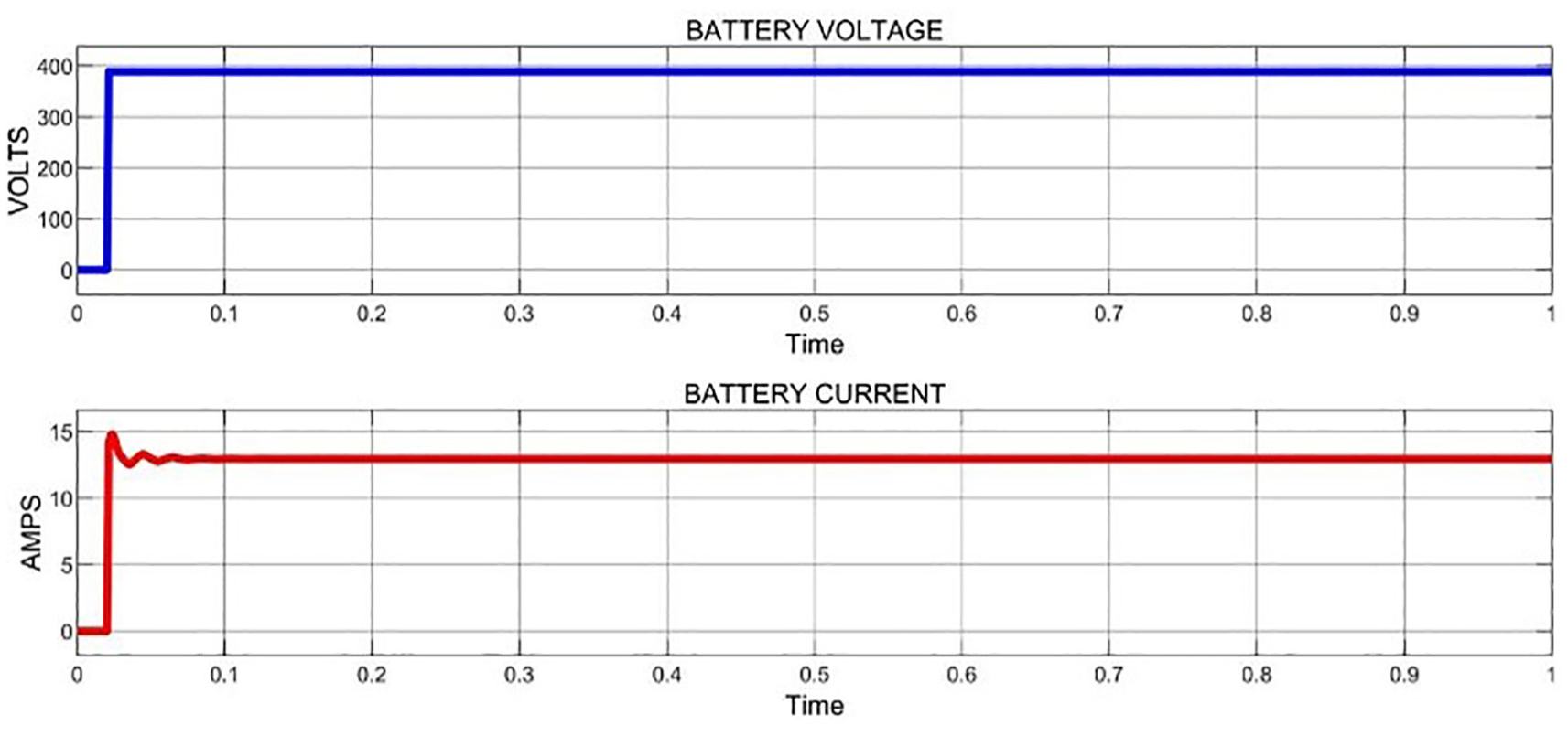
Battery’s current and voltage waveform.
Upon inspection using a digital multi-meter, the physical output of the system revealed a voltage reading of 14.9 V ± 0.5 through the receiver unit. This measurement was obtained without connecting any load, as depicted in Figures 15 and 16. These findings demonstrate the potential voltage output capability of the system, which serves as a valuable reference for further analysis and evaluation of its performance under varying load conditions.

Experimental setup results.
Experimental setup.
The given experiments, the configuration layout, and the established finds present a strong framework for future studies and advancements of WPT systems intended for electric vehicles. The information from this study provides a proper understanding of how to progress toward the effective WPT systems’ development that will improve the usage of electric vehicles through increased convenience, safety, and environmental friendliness of the charging systems.
Future work and recommendations
The analysis presented in this research paper primarily aims at the application of WPT for deep-cycle lithium-ion batteries in EVs by employing inductive coupling has shown great promise and effectiveness. Nonetheless, several areas are still promising for further exploration and improvements to uplift the technology and its utility.
Enhancing coil design and alignment
When using inductive coupling WPT systems, one of their major drawbacks is the problem associated with the misalignment of the coils. Further studies should examine ways of creating stronger coil designs to maintain power density when there are misalignments present. There is always the possibility of generating more complex novel materials and shapes to enhance the distribution of the magnetic field.
Dynamic wireless charging systems
It is recommended that research be conducted in the future to enhance such systems from the aspect that would make them more feasible, most especially in the provision of infrastructure for dynamic charging lanes as well as safety and reliability in such systems.
Integration with IoT and smart grid technologies
Some benefits that can be gained through the connection of WPT systems with smart technologies such as the IoT and smart grids include improved control and efficiency. There are possibilities for creating a real-time SC controller enabling real-time monitoring and control of the power flow depending on the SoC condition of the vehicle, traffic condition, and availability of energy power.
Optimization of power electronics and compensation networks
WPT systems are quite efficient, with the power electronics and compensation networks must be at optimal levels. Further work should be directed to enhance these components and the common approach is to work on minimizing losses, as well as managing thermal loads.
Conclusion
This paper presented the design and performance analysis of a resonant inductive coupling-based wireless power transfer (WPT) for deep-cycle Li-ion batteries of electric vehicles (EVs). The system achieved a power transfer efficiency of 78% with varying coil separation distances, proving its effectiveness in real applications. The study also highlighted the importance of coil design, coil alignment, and compensation networks in transferring power. The system’s performance was achieved by employing a resonant frequency of 70 kHz and optimized coil geometry. Simulations using ANSYS Maxwell and MATLAB were close to experimental results, indicating the system’s mathematical models and overall design. The findings can be used to advance WPT systems for EVs, enabling more convenient, efficient, and accessible charging.
Future works may address issues like coil misalignment, dynamic charging during vehicle motion, and improving magnetic coupling using metamaterials. The findings provide valuable knowledge for developing effective WPT technologies for electric vehicles, enhancing adaptability, safety, and eco-friendliness. Future experiments may also include thermocouples to monitor the temperature of key components such as the battery, coils, and capacitors. This will provide valuable insights into the thermal dynamics of the system.
Footnotes
Appendix
Acronyms table.

| Abbreviation | Description |
|---|---|
| WPT | Wireless power transfer |
| EV | Electric vehicles |
| V2G | Vehicle-to-grid |
| IPT | Inductive power transfer |
| OLEV | On-line electric vehicle |
| SOC | State of charge |
| PCB | Printed circuit board |
| TX | Transmitting coil |
| RX | Receiving coil |
Acknowledgements
The authors would like to thank colleagues for suggestions to improve paper quality.
Handling Editor: Aarthy Esakkiappan
Declaration of conflicting interests
The author(s) declared no potential conflicts of interest with respect to the research, authorship, and/or publication of this article.
Funding
The author(s) disclosed receipt of the following financial support for the research, authorship, and/or publication of this article: This research was funded by the National University of Computer and Emerging Sciences – FAST faculty research support grant (FRSG-2023) program, Pakistan.