
Abstract
Wireless charging has become an emerging challenge to reduce the cost of a conventional plug-in charging system in electric vehicles especially for supercapacitors that are utilized for quick charging and low-energy demands. In this article, the design of an efficient wireless power transfer system has been presented using resonant inductive coupling technique for supercapacitor-based electric vehicle. Mathematical analysis, simulation, and experimental implementation of the proposed charging system have been carried out. Simulations of various parts of the systems are carried out in two different software, ANSYS MAXWELL and MATLAB. ANSYS MAXWELL has been used to calculate the various parameters for the transmitter and receiver coils such as self-inductance (L), mutual inductance (M), coupling coefficient (K), and magnetic flux magnitude (B). MATLAB has been utilized to calculate output power and efficiency of the proposed system using the mathematical relationships of these parameters. The experimental setup is made with supercapacitor banks, electric vehicle, wattmeters, controller, and frequency generator to verify the simulation results. The results show that the proposed technique has better power transfer efficiency of more than 75% and higher power transfer density using a smaller coil size with a bigger gap of 4–24 cm.
Keywords
Introduction
Electric vehicles (EVs) are being considered as a viable solution for ecological and economic concerns such as global warming, glasshouse gas emissions, and fossil fuel resources reduction. In such vehicles, wireless charging has become an emerging challenge to reduce the cost of a conventional plug-in charging system. Currently, the widely used method to charge EVs is plug-in charging of EVs but it has serious disadvantages such as cost and proper maintenance.1,2 Wireless charging is an alternative method that can be utilized to convey energy to a Metro Bus while travelers disembark and embark. 3 One way to wirelessly charge EVs is inductive charging or inductive power transfer (IPT) that uses variable magnetic fields to cover the air gap between the primary coil and EV chassis to transmit high power. 1
The block diagram for a basic wireless charging IPT system for an EV at high frequency (100 kHz) is shown in Figure 1. The input alternating current (AC) voltage is step down to 80 V AC using a step-down transformer. This step-down AC voltage is then converted to direct current (DC) voltage using a rectifier circuit. Then a chopper circuit is utilized to generate a square wave of 100 kHz. This square wave is then fed to the compensation capacitor bank to minimize the losses and finally, the 100-kHz square wave after compensation capacitors are fed to transmitting coil. The transmitted power is then received by the receiving coil and the received power is then fed to DC load after passing through secondary compensation capacitors and rectifier. The DC load can be a battery or a supercapacitor bank.
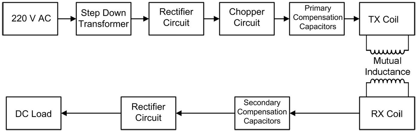
Block diagram of a high-frequency wireless charging system of electric vehicle.
Inductive charging system faces different issues like achieving resonant frequency, bifurcation of system, misalignment of coils, shape of coils, and air gap; therefore, proper design of charging stations is required to overcome these issues.4,5 There are two ways to charge EV through IPT which can be classified as dynamic and static charging systems.6–8 In this article, we have worked on the static charging system. We have used supercapacitors instead of batteries because these could be more rational than batteries due to quick and incessant wireless charging and discharging without chemical reactions; large number of recharge cycles life; quick and high effective charge/discharge, precise voltage-based state-of-charge (SOC) measurement; a wide working temperature scope of −40°C to +70°C and little spillage current and ecologically benevolent without utilizing substantial metal for its structure material.9–11
Wireless power transmission (WPT) is a rapidly adopted technique in the transportation sector and various technical approaches are being used for its implementation in which different variations of certain parameters, for example, a number of coils, the shape of coils, compensation topologies, inverter design, and frequency controls are being implemented to get maximum power and efficiency.12–15 A detailed review of recent trends in WPT techniques is presented in Sun et al., 16 in which the authors discussed different applications of WPT for EVs. The authors highlighted the difference between static and dynamic charging of EV and explained the different combinations of coils in different forms. In another review, Chirag Panchal analyzed different shapes of coils and discussed the use of ferrite in different applications. He also suggested using aluminum plating due to their shielding property and structural integrity. The author discussed the negative point of the WPT system, that is, health and safety issues in detail. 8 The advantages of WPT in Internet of Things (IoT) technology are described by He et al., 17 by removing conventional power sources like batteries. Economic analysis of dynamic charging of EV with the real-world data obtained from the running project of online electric vehicle (OLEV) in South Korea by Seungmin Jeong. The author claimed that although initial investment on dynamic charging is more, it will save much more cost accomplished from the extended battery life. 18
Improved compensation topologies and power inverters were proposed by Giuseppe Buja, in building a WPT system which is operated at the frequency of 85 kHz and capable of providing 560 W at an air gap of 0.1–0.2 cm between coils of 0.38 m diameter with the efficiency of 77%. The author focused on improved compensation topologies and power inverters. 12 A prototype that is capable of providing 2.2 kW with coils of 40 cm diameter made with Litz wire by Nan Liu. A variable-frequency control method is proposed that is a feedback circuit which is capable of auto-tune the switching frequency to resonant frequency by changing the distance between coils to improve the efficiency of the system. A universal control method is also proposed in which different circuitries were used for the detection of frequencies, variable-frequency control, and selection of different frequencies for different types of load (light, mid, or heavy). It was proposed that an additional inductor can be added in the primary setup of the inductor–capacitor (LC) circuit to keep frequency constant and minimize the influence of air gap and misalignment between coils on certain frequency.5,19
The equivalent model circuit of series resonant WPT system is shown in Figure 2 where L1, L2 are self-inductances of two coils, M is mutual inductance between two coils, and r1, r2 are copper losses of coils. As both coils are air-cored, therefore, the iron losses have been neglected in this study. Both transmitting and receiving coils are connected with series compensated capacitors C1 and C2. RC1 and RC2 represent internal resistance of capacitors. rp is the impendence of high-frequency AC power source and RL is the load resistance.

Proposed topology for WPT system. 20
For a given WPT system, the optimal loading capacitance and impendence can be written as


where RS1 and RS2 are the sum of the source and load side resistances, respectively. Equations (1) and (2) represent the resistance matching condition and equations (3) and (4) represent the resonance matching condition. 9 These two conditions are necessary to consider for maximum WPT. From equations (3) and (4), it can be observed that for maximum power transmission, the two coils must operate on resonance frequency as

From equations (1)–(4), we can choose optimal parameters for maximum power transfer system. But for a pre-arranged WPT system, the above parameters RC1, RC2, rP, and RL are static.
The WPT system depicted in Figure 2 can be analyzed using Kirchhoff’s voltage law (KVL) as


where


Also, M is mutual inductance between transmitter (TX) and receiver (RX) coils, and M can be calculated as

The impedances Z1 and Z2 for TX and RX sides of the equivalent circuit can be written as


The two-loop equations (6) and (7) can be written in the form of impedances Z1 and Z2 as


Now, the final equations for input power drawn by TX coil and output power supplied by RX coil to load can be written as


where
Finally, the overall efficiency of the series compensated inductively coupled system can be derived as

From equation (17), we see that the efficiency of WPT system depends upon the load resistance RL, current on receiving side I2, and supply voltage VS and current on transmitting side I1. It is also clear that efficiency is directly proportional to load resistance RL, square of current on receiving side I2 and inversely proportional to supply voltage VS, current on transmitting side I1, and the angle between VS and I1. Another very important observation in getting maximum output form WPT system is resonance. To get resonance for WPT system, we have to make sure that the resonance frequency of the TX side and RX side must match with each other. The resonance frequency can be written as

In this article, our contribution is the design of efficient wireless charging system for supercapacitor-based EVs with greater distance and smaller coil size. The proposed method is very much significant in terms of applications in practical metro-based stations where the bus stops for a short duration for embarking/disembarking of passengers. The supercapacitors will get charged instantaneously during this time by this WPT system and these supercapacitors can then provide energy for the bus.
Further contents of this article are organized such that research methodology is described in section “Research methodology.” Simulation and experimental design results are presented in section “Results and discussion.” Finally, the conclusion is presented in section “Conclusion” with future work directions.
Research methodology
The model IPT framework includes the design of transmitting and receiving coils, a high-frequency signal generator, high-frequency inverter and rectifier circuits, supercapacitor bank as a quick and highly effective charge/discharge source, and measuring devices to measure SOC of supercapacitor bank. All these components for an EV’s powertrain and charging agenda are implemented, as shown in block diagram of Figure 3.

Proposed design for IPT.
Software ANSYS MAXWELL was used to obtain simulation parameters for TX and RX coils such as self-inductance (L), mutual inductance (M), coupling coefficient (K), and magnetic flux magnitude (B). MATLAB was used to calculate the output power and efficiency of the proposed system. The experimental setup was made in such a way that input and output power was measured by connecting a filament rod as the load on the RX side by changing the distance between TX and RX coils. The source used on TX side was of 80 V and 5 A DC power supply. The resonant frequency of the TX and RX side was matched using compensation capacitors bank of 12.832 nF on both sides. The experimental setup is shown in Figure 4 in which there are two DC wattmeters for input and output power measurements and an STMicroelectronics (STM) controller for generating a source of 100 kHz.
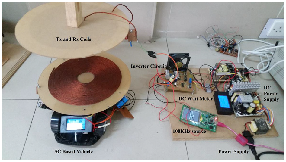
WPT system prototype.
Supercapacitor-based EV is shown in Figure 5 in which RX coil is mounted on the vehicle top and EV is carrying on-board supercapacitor module, a rectifier circuit, DC–DC circuit, and RX coil.
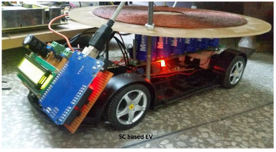
Supercapacitor-based EV.
Results and discussion
Simulation results
Single-coil model
A flat spiral coil shown in Figure 6 was designed and simulated with parameters mentioned in Table 1. Two identical coils were designed for TX and RX coils for maximum efficiency and overcoming the issues of misalignment.

Proposed transmitting and receiving coil.
Coil parameters.

SWG: standard wire gauge.
The self-inductance (LS) of the coil was obtained 197.96 µH when tested with 100 kHz and a coupling coefficient of 1.
Two-coil model
A two-coil model was simulated to represent TX and RX coils separately for measurement of different parameters between these coils, as shown in Figure 7. A suitable and practical range of distance and misalignment factors were selected, that is, distance from 2 to 24 cm and misalignment along the horizontal axis from 0 to 50 mm. For each value of distance and misalignment, the following measurements were made for TX and RX coils:
Self-inductance (L);
Mutual inductance (M);
Coupling coefficient (K);
Magnetic flux magnitude (B).

Two-coil setup.
Mutual inductance (M) and coupling coefficient (K)
The values of K and M decrease with the increase in misalignment and distance between coils. The plot for M and K is shown in Figure 8 that is similar because of the relation between K and M, as shown in equation (10).

Matrix1.L (TXC1, RXC1); effect of distance and misalignment on the value of K and M.
Self-inductance (L)
The value of self-inductance (L) of both transmitting and receiving coil is almost constant but the slight change (209.93–209.99 µH) in the value of self-inductance is due to the magnetic effect of both coils on each other. From the graph in Figure 9, it can be seen that the self-inductance value varies in decimal points only. Moreover, the value of self-inductance in the single-coil model (i.e. 197.96 µH) is different from a double coil model (i.e. 209.9 µH). This difference is due to the fact that the self-inductance (L) is affected by the RX coil placed in its field in the two-coil model presented in Figure 4 when the injecting source is fed from TX coil in ANSYS Maxwell software.

Effect of distance and misalignment on the value of self-inductance (L).
The magnetic flux (B)
The magnetic flux between TX and RX coil is also affected by the varying distances and misalignments between coils, as shown in Figure 10.
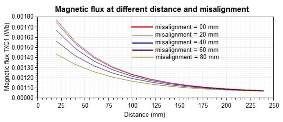
Effect of magnetic flux at different distances and misalignments.
This distribution of magnetic flux between coils is shown in Figure 11. It can be noted from Figure 9 that very high value of magnetic flux (shown with red color) is very close to the coils and the flux in far-field is of moderate magnitude (shown with green color). From this explanation, we can conclude that our proposed prototype is not harmful to living and external objects present in its surroundings and far-field. 4

Effect of magnetic flux distribution at a certain distance and misalignment.
The mathematical model was implemented in MATLAB to simulate output power and efficiency of the system. The parameters shown in Table 2 are used to get maximum output power and efficiency.
WPTS parameters used in MATLAB.

WPTS: wireless power transfer system; AC: alternating current.
The output power plot for different values of coupling coefficient K and the range of frequency F are shown in Figure 12. It can be observed that there are two peaks of output power (frequency splitting) but maximum power is obtained when the system becomes resonant at 100 kHz on a certain value of K.

Output power 3D plot of WPTS.
Efficiency plot is shown in Figure 13 that shows the plot of maximum efficiency, that is, 77%, which is also at the resonant point.

Output efficiency plot of WPTS.
The simulated results of wireless power transfer system (WPTS) prototype in the form of different outputs that is coupling coefficient, distance, input power, output power, and efficiency have been mentioned in Table 3.
WPTS Simulation Results.

WPTS: wireless power transfer system.
The graphical presentation of distance, output power, and efficiency of proposed WPTS is shown in Figure 14.

Distance versus power and efficiency.
Experimental results
The experimental results are shown in Table 4 in which value of coupling coefficient (K) is obtained from the results of two-coil model implemented in ANSYS Maxwell and the value of output power is obtained from the results of the mathematical model implemented in MATLAB.
Output power and efficiency of WPTS at different distances.

WPTS: wireless power transfer system.
The graph of output power and efficiency against different distance is shown in Figure 15.
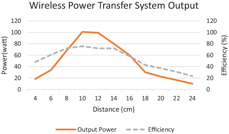
Measured distance versus measured output power and measured efficiency.
The results in Table 4 and Figure 15 show that it is not necessary to keep a minimum distance to get maximum output power and the maximum power is obtained at a distance of 10 cm rather than minimum distance, that is, 4 cm. This proves that in WPTS, certain distance is required to get maximum output power at which our system becomes completely resonant and both coils strongly couple with each other without loss of coupling and magnetic flux. The similar behavior can be verified in simulated output power result from Figure 14.
Figure 16 shows the graph of simulated and measured power. It is clear from the graph that the measured and simulated results have a good correlation.

Graph of measured and simulated output power against distance.
In order to charge supercapacitor bank via wireless charging, the bank is attached as load after rectifier circuit. While charge storage increases in the bank, its terminal voltage also increases. The plot in Figure 17 shows the charging behavior of the supercapacitor bank as a function of time. From the plot, it is clear that it takes 306 s to charge up to 15 V. The plot is almost straight line due to constant charging current.

Charging time as a function of supercapacitor bank volts.
Comparison with the existing technique
A two-coil wireless power transfer technique is discussed in Zhou et al. 21 Zhou et al. 21 have designed the whole system at a high frequency (640 kHz). Due to this high-frequency, ultrafast metal–oxide–semiconductor field-effect transistors (MOSFETs) are required to design the inverter circuit which will make the inverter design more complex and expensive. Moreover, the size of the coil is also large. The radius of the two coils is 20 cm and they are winded by 19 turns using Litz cable with 500 strands. With this high frequency and bigger coil size, they were able to achieve 20 W output power with only 22%–30% efficiency. Due to bigger coils, the distance between the coils can be a maximum of 2.2 meters. However, in our proposed technique, we have designed the system for the frequency of 100 kHz which is much lower than that in the study by Zhou et al. 21 It will make the inverter circuit less expensive and commonly available MOSFETs can be used for the inverter. The other advantage of our system is the improved and smaller coil size. In our system, the radius of coils is 12.05 cm and they are winded by 39 turns using Litz cable with only 50 strands. With such light and small coils, we were able to get approximately 100 W output power with a maximum of 75% efficiency. Reducing the coil size and still getting a handsome amount of power at the receiver coil is a big improvement. Table 5 highlights the improvements made in our design.
Comparison of our technique with the technique used in Zhou et al. 21

Conclusion
In this article, the design of an efficient WPT system was presented using a resonant inductive coupling technique for supercapacitor-based EV. Mathematical analysis, simulation, and experimental implementation of the proposed charging system have been carried. Simulation of various parts of the systems was carried out in two different software, ANSYS MAXWELL and MATLAB. The experimental setup was made with supercapacitor banks, EV, wattmeters, microcontroller, and frequency generator to verify the simulation results. The results show that the proposed technique has better power transfer efficiency of more than 75% and higher power transfer density using a smaller coil size with a bigger gap of 4–24 cm. Future work may include consideration of heating effects and an increase in the length of routes of EVs.
Footnotes
Handling Editor: James Baldwin
Declaration of conflicting interests
The author(s) declared no potential conflicts of interest with respect to the research, authorship, and/or publication of this article.
Funding
The author(s) received no financial support for the research, authorship, and/or publication of this article.