
Abstract
In this paper, a three-dimensional partial integrated guidance and control law for the supersonic missile impacting the surface target is proposed. In the guidance loop design, a reduced-order extended state observer is integrated with feedback linearization and the pure proportional navigation law to eliminate the effects of the unknown target kinematics and the dynamic coupling between the vertical and horizontal planes. Considering the autopilot lag, two guidance schemes with different observer inputs are compared using the adjoint and frequency domain analyses. For the control loop, the angular velocity feedback is performed first for the pitch and yaw channels as conventionally done in practice, and then first-order linear active disturbance rejection control is designed for the damping-enhanced plant to deal with the fast time-varying, uncertain aerodynamics and the strong coupling effects among the three channels. Both the attitude angle and the acceleration control can be designed in a unified framework. Finally, a three-dimensional engagement scenario is performed using a six-degree-of-freedom supersonic vehicle model, and extensive simulations are carried out to validate the robustness and the high guidance precision of the proposed method.
Keywords
Introduction
Due to the advantages of penetration ability and lethality, supersonic missile has been used widely. When impacting a surface target in the terminal guidance phase, the maneuverability of a supersonic missile is restricted and the time available for engagement is relatively small due to its high speed. In addition, the signal-to-noise ratio of the seeker measurement is relatively low due to the complicated background of the target. As a result, the miss distance may be large. Therefore, the guidance and control system design is extremely critical to achieve satisfactory impact performance.
Extensive investigations have been devoted to the high-performance guidance and control design. In general, the design philosophy can be categorized into three classes: separate design, single-loop integrated design, and two-loop integrated design (partial integrated design). In the conventional separate design, the guidance and control systems are designed independently as two loops, wherein an inner-loop autopilot is constructed to follow the acceleration command provided by the outer-loop guidance law.1–3 These two subsystems are then integrated and subsequently modifications are conducted iteratively to each system in order to achieve desired overall performance. Obviously, such an approach does not exploit the synergistic relationships between the interacting subsystems and excessive design iterations may be performed. This problem is more critical for the endgame phase when the spectral separation might not be valid due to the rapid change of the interception geometry. Consequently, an alternative approach that can fully consider the nonlinear interactions between the engagement kinematics and the missile dynamics is demanded, motivating the integrated guidance and control (IGC) design.
A variety of single-loop IGC algorithms have been proposed in the recent literature. Techniques like linear quadratic optimal control,4–7 state-dependent Riccati equation approach,8,9 suboptimal θ-D method, 10 generalized extended state observer (GESO)-enhanced predictive control, 11 feedback linearization,12,13 and zero-effort-miss (ZEM)-based sliding mode control14–16 have been applied successfully in the single-loop IGC framework. Among these methods, optimal control is the most intuitive design that can synthesize an overall optimal IGC system subject to certain performance index. In previous works,4–7 integrated linearized model was established first so that the linear quadratic optimal control could be employed. However, the linearized model cannot reflect the physically nonlinear dynamics when the line of sight (LOS) angular rate changes rapidly. Consequently, guidance precision may be reduced in such scenarios. To solve this problem, state-dependent Riccati equation approach was utilized in previous works.8,9 The nonlinear plant can be parameterized to a state-dependent linear form and then the state-dependent Riccati equation can be solved online. To reduce computational complexity and avoid the information about time-to-go, the θ-D method was proposed in Xin et al. 10 to obtain an approximate closed-form suboptimal feedback controller for the nonlinear infinite horizon IGC problem. Instead of optimal control, predictive control was employed in Panchal et al. 11 The target acceleration, model nonlinearities, and model uncertainties can be estimated by the GESO, and then the integrated missile-target engagement dynamics can be compensated into a linear form to use predictive controller straightforwardly. Feedback linearization method was employed in Menon and colleagues12,13 to transform the nonlinear model into Brunovsky’s canonical form in order to employ linear quadratic regulator (LQR) 12 or pole placement 13 method. Although feedback linearization is a powerful tool to handle nonlinearities, the robustness is relatively fragile when there exist large model uncertainties. For more details of other nonlinear IGC design methods, readers can refer to previous works.14–22
As indicated in previous works,23–26 the single-loop IGC scheme tends to tackle the problem more from the guidance point of view, and quick maneuvers may cause the short-period dynamics to go unstable due to the inherent timescale separation characteristic. This is because the control surface directly responds to the relative position error in the IGC scheme. However, the effectiveness of the control surface on the aerodynamic force is much smaller than that on the aerodynamic moment. As a result, excessive moment tends to be generated when correcting the relative position error and the fast short-period dynamics may be destabilized. In practice, it is desired that the stability of the missile should be guaranteed even when the guidance law is inactive. Thus, partial integrated guidance and control (PIGC) design which is executed in two loops was proposed.6,7,23–29 Both the guidance loop and control loop are reserved in the PIGC scheme. In Levy et al.,6,7 the inner autopilot was designed independent of the guidance law, while all the dynamic states were also used in the outer guidance loop. It can be proved that such a full-state two-loop architecture is equivalent to a full-state single-loop one under some conditions. Therefore, the full-state two-loop design is preferred since it ensures a stabilized missile dynamics. In previous works,23–29 the outer-loop took the angular rate instead of the acceleration as the virtual input, and the inner-loop was designed to track the angular rate command. In this way, the intermediate loop from the acceleration command to the angular rate in the conventional scheme is removed and the overall settling time can thus be reduced.
Motivated by the above analysis, a type of PIGC scheme for impacting the surface target is proposed in this paper. There are two kinds of integrated models for the IGC design, the relative position–based model and the LOS angle–based model. The impact strategy of the relative position model is to drive the relative range (or the ZEM) to be zero,6–8,10–12,14–16,23–26 while the LOS angle model–based design is to drive the LOS angular rate to be zero.4,5,9,13,17–19,27–29 Since the measurement error of the relative range is much larger than that of the LOS angular rate, the guidance precision may not be guaranteed for the relative range–based design. Consequently, the LOS angle model is chosen in this paper. The proposed scheme operates in a two-loop structure which fully exploits the timescale separation that inherently exists between the rotational and translational motion. The outer-loop guidance laws provide the acceleration commands for the pitch and yaw channels, and the inner-loop autopilots are designed separately to track the acceleration commands. The outer-loop guidance law design uses not only the variables in the engagement model but also the inner-loop acceleration outputs, which means that the real-time autopilot dynamics is considered in the guidance law. Thus, this method can be considered as a type of partial integration scheme that combines the conventional hierarchical configuration and the philosophy of IGC of achieving tighter integration of the subsystems. The proposed PIGC architecture is similar to that in Levy et al.6,7 wherein the dynamic states were also used in the guidance loop to achieve the integration. The main contributions of this paper can be summarized as follows:
In the guidance loop, the dynamical coupling between the elevation and azimuth LOS angles is eliminated through the feedback linearization. Reduced-order extended state observer (RESO)30–32 is integrated into the pure proportional navigation (PN) guidance law to compensate the unknown target maneuver. In the first guidance law (called PIGC-A for the sake of brevity), the autopilot lag is neglected and the control input of the RESO is the practical acceleration. While in the second guidance law (called PIGC-AC), the autopilot lag is regarded as part of the total disturbance and the control input of the RESO is the acceleration command. The adjoint and frequency domain analyses are utilized to compare these two schemes. The bandwidth and the phase characteristic of the guidance loop of PIGC-A can adapt with the autopilot time constant, which well reflects the point of partial integration. In this way, bandwidth match between the two loops can be ensured and satisfactory damping can be achieved, thus improving the guidance precision.
A hybrid bank-to-turn (BTT) and skid-to-turn (STT) autopilot is designed based on linear active disturbance rejection control (LADRC). 31 For the pitch and yaw channels, damping augmentation is conducted first and thus the high-frequency mode can be neglected. Then, first-order LADRC is needed to provide satisfactory tracking and disturbance rejection performance. All the time-varying dynamics, uncertainties, and couplings are lumped into the total disturbance and estimated by the RESO. Both the attitude angle and the acceleration control can be designed in a unified framework, which facilitates the design process greatly.
This scheme is proposed considering the practical application. The two-loop structure design can facilitate the parameter tuning, which can guarantee the required robustness performance in practice. The approximate linear forms of the guidance and control laws make the frequency domain and adjoint analyses applicable. Excellent disturbance rejection abilities can be achieved by employing the RESO compared with the traditional methods. In addition, the guidance loop can adapt with the autopilot dynamics, which makes the entire system tighter.
This paper is organized as follows. Three-dimensional (3D) nonlinear engagement model and 6-degree-of-freedom (6-DOF) dynamics of the missile are described in section “Problem formulation.” Design and analysis of two types of guidance laws are presented in section “Guidance law design.” In section “Control system design,” the BTT/STT autopilot design is given. Comparison of the two guidance laws based on the adjoint analysis is conducted in section “Comparison of two guidance laws.” Simulation results on the 6-DOF nonlinear model are shown in section “Simulation result.” Concluding remarks are offered in section “Conclusion.”
Problem formulation
The mathematical model of the 3D engagement and the missile dynamics are given in this section. Figure 1 shows the typical 3D purser evader engagement scenario, wherein the subscripts m and t represent the missile and the target, respectively;
where
where

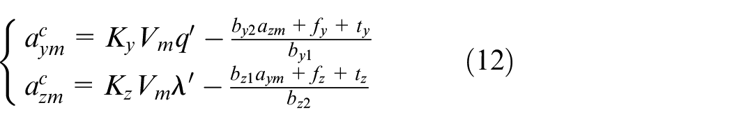
The input gains of the accelerations can be expressed as (for the air-to-surface missile considered in this paper, it can be assumed that
and
and
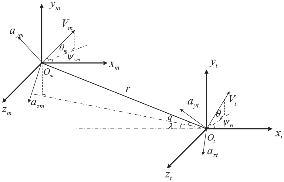
3D purser evader engagement scenario.
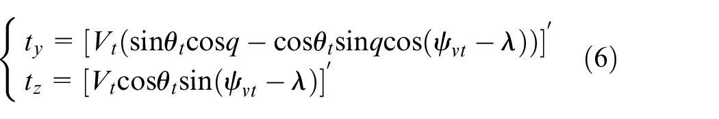
It is well known that a direct impact can be achieved by controlling
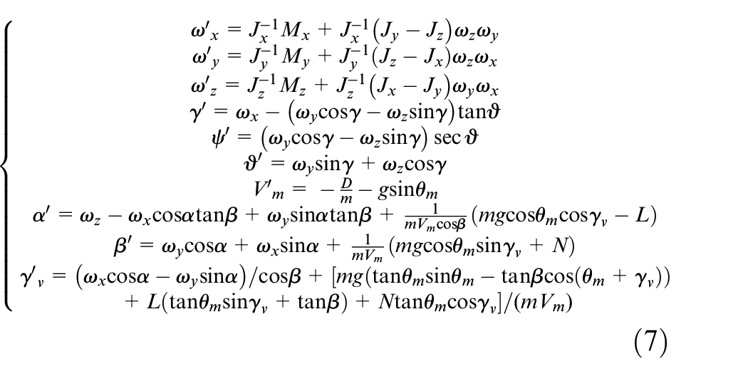
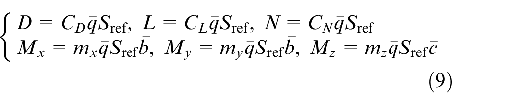
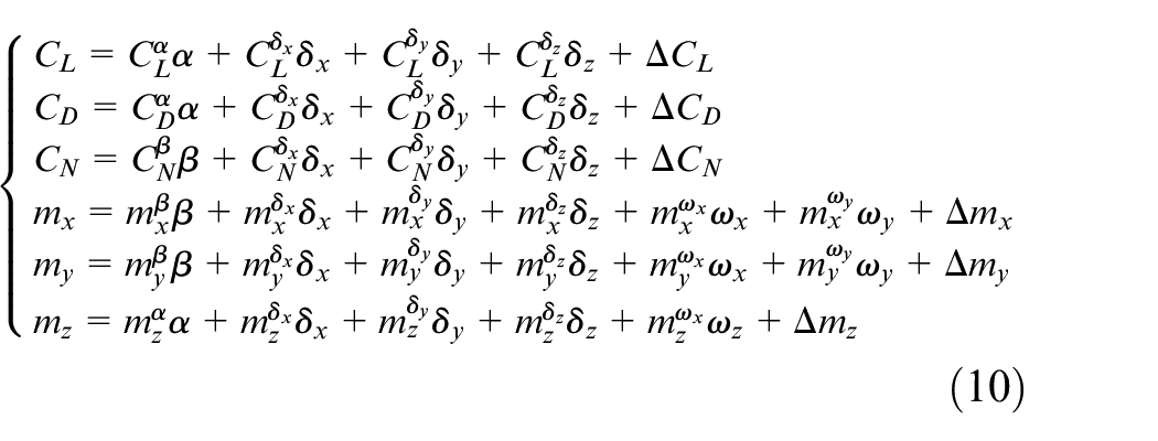
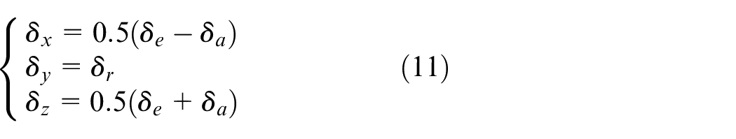
The 6-DOF dynamics of the missile are given by
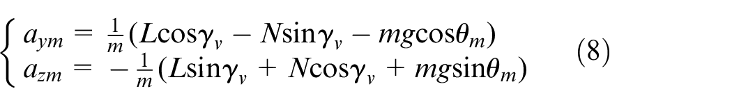
and the normal accelerations are in the form of
where
where
The objective of the autopilot design is to track the acceleration commands fast and accurately. In this paper, hybrid BTT and STT control is utilized for the autopilot. The control method is required to handle the multiple uncertainties as well as the strong kinematic, aerodynamic, and inertia coupling effects among the three channels in the BTT/STT mode. To summarize, the goal of the PIGC design is to achieve impact with high precision in spite of the multiple coupling and uncertainties mentioned above.
Guidance law design
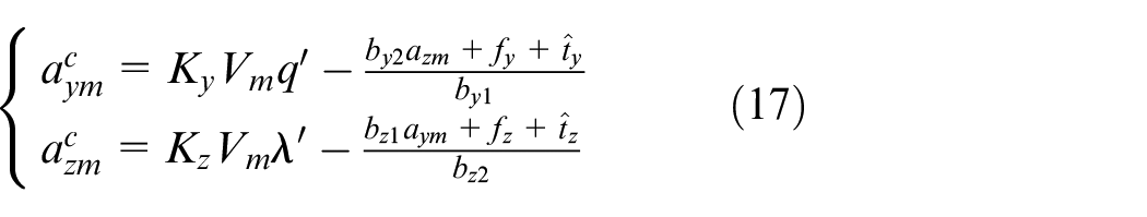
According to equation (2), an ideal acceleration command based on the feedback linearization can be designed as
where
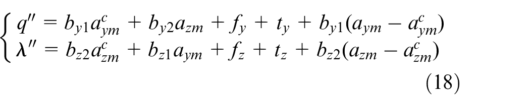
It can be seen that the two planes are decoupled and the target maneuver can be compensated in this way. Compared with the full-order extended state observer (ESO), the reduced-order ESO has the advantages of smaller phase lag and stronger robustness to the plant time-delay.31,32 Thus, two RESOs are designed to obtain the estimations of
and
where
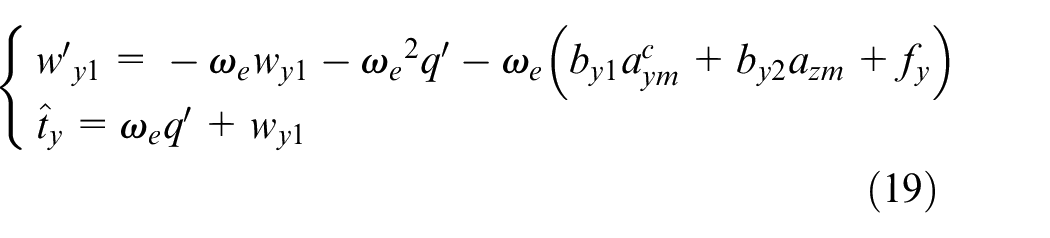
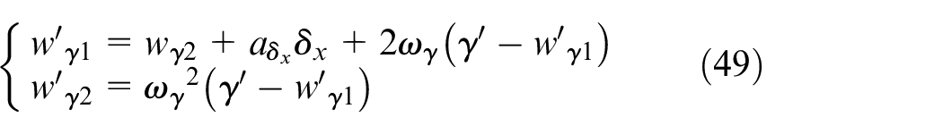
which shows that the estimations are the filtered values of the true disturbances in essence. The selection of the observer gains should consider the observation precision and the sensitivity to the unmodeled high-frequency dynamics as well as the measurement noise simultaneously. 35 Then, the guidance law, which is called PIGC-A for conciseness, becomes
In the above design process, the autopilot dynamics is ideally considered as 1, while in fact there exists a lag in the autopilot response. To compensate the response lag, first or higher order autopilot dynamics was integrated into the guidance kinematic equations in the previous research36,37 and the controller design was performed within the back-stepping framework. However, higher derivatives of the LOS angular rates, which are difficult to be obtained in practice, are demanded in these methods. Since the time constant of the autopilot is much smaller than that of the guidance loop in the most time of the terminal phase, we attempt to include the autopilot lag in the total disturbance and thus equation (2) can be reformulated as
and the reduced-order observers in this case become
and
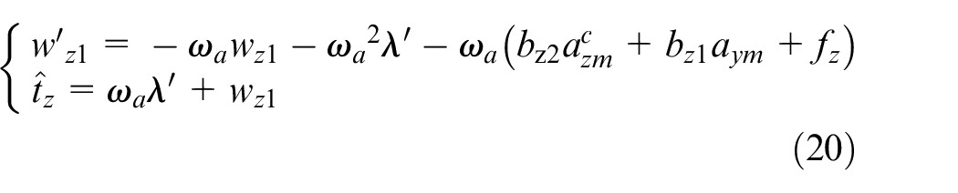
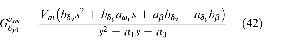
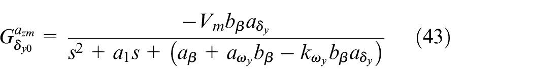
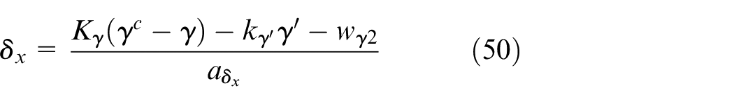
The only difference is that the control input in the observer is the acceleration command instead of the practical acceleration. This new type of guidance law is called PIGC-AC. Frequency domain analysis is performed next to further illustrate the difference. The vertical plane is taken as an example. The acceleration commands of the two schemes are represented by
After some mathematical manipulations, one can obtain
It can be observed that the nature of PIGC-AC is the proportional integral (PI) control of the LOS angular rate plus an additional decoupling term, which is independent of the autopilot dynamics. Whereas the equivalent form of PIGC-A is the PIGC-AC cascaded with a lead-lag compensator. The lead-lag compensator is related to the autopilot lag and the observer gain directly.
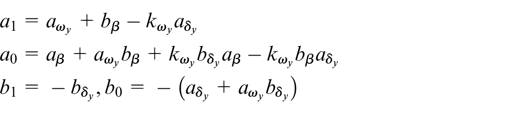
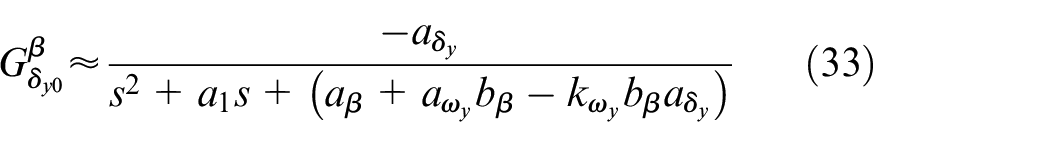
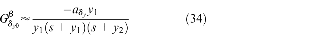
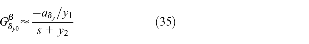
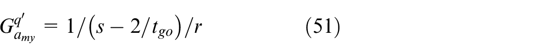
For the supersonic air-to-surface missile in this paper, the missile velocity is much larger than that of the target. Suppose that the missile velocity is constant and the motion is near the collision triangle, and then
where
Control system design
BTT/STT command logic
In this paper, hybrid BTT and STT control is utilized for the autopilot. At the beginning of the terminal guidance phase, BTT control is employed to enhance lateral maneuverability. In the endgame phase, STT control is used to avoid the command oscillation of the roll angle caused by the small acceleration command and the measurement noise of the LOS angular rate. In the BTT mode, the bank angle command is
The bank angle control is realized by transforming the command into that of the roll angle via
Since
where
Within a specified range, the BTT mode is switched to the STT mode to prevent the frequent switching. In the STT mode, the roll angle is stabilized and the commands in the pitch and yaw channels are just
Lateral control
In this section, LADRC-based autopilot design is introduced. Due to the symmetry between the pitch and yaw channels, only the yaw channel design process is presented.
In the BTT mode, sideslip angle should be controlled to be zero to reduce the lateral coupling moments. Combining equations (7), (9), and (10) can obtain
where
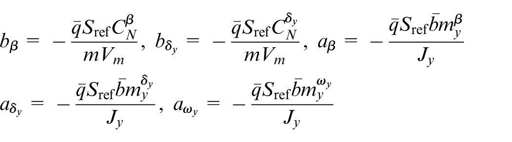
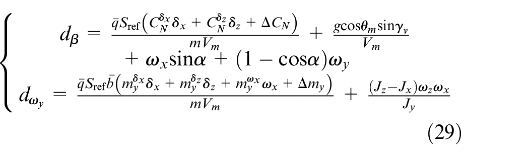
Differentiating the sideslip angle dynamics with respect to time yields
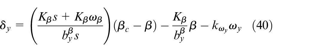
The yaw angular rate feedback is first performed to enhance the damping as

where
where
According to our practical experience,
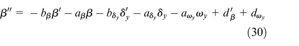
It can be seen that the angular rate feedback can enhance the damping characteristic evidently and thus the dynamics can be further simplified as an over-damping plant. Assume that
Suppose that
Now the reduced-order sideslip angle dynamics can be written as
where
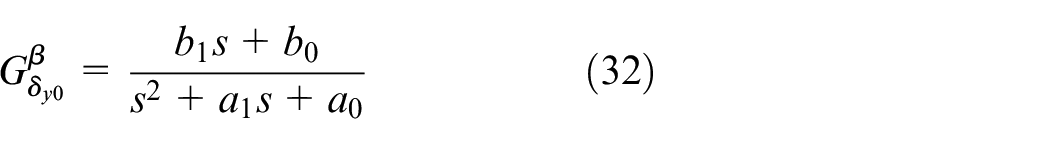
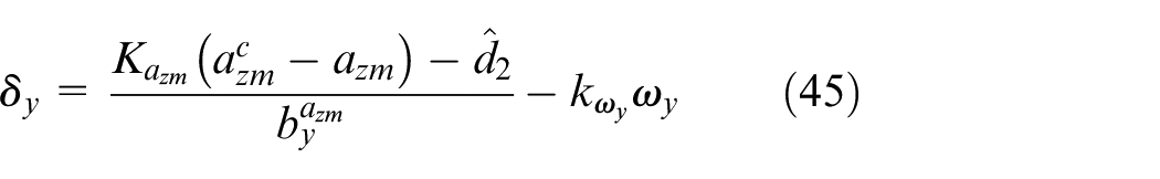
where
Combined with equation (31), the final control law becomes
Through Laplace transformation, the control law can be reformulated in the frequency domain as
The equivalent PI gains in the proposed method are time-varying with
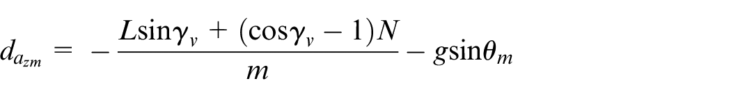
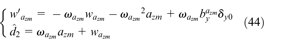
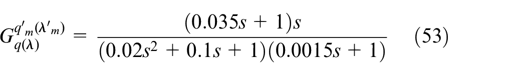
The acceleration control in the STT mode is conducted based on the sideslip angle control design presented above. Substituting equations (9) and (10) into (8), one can obtain

where
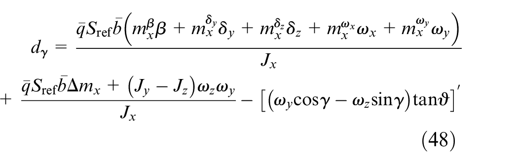
To perform the analysis,
Still the terms with
which is just
and
From the above design procedure, it can be seen that the angle of attack, sideslip angle, and acceleration can all be controlled in a unified framework, which facilitates the design and tuning process greatly.
Roll Control
The roll dynamics can be written as
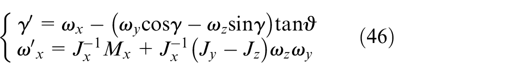
Differentiating

where
Also, RESO can be designed to estimate the total disturbance
and the control law is designed as
The tuning for the designed autopilot is based on the stability margin tester method.39–41 It is worth noting that though LADRC is a linear control method, its design concept is totally different: it can be applied to nonlinear, time-varying and uncertain process with very little model information. The total disturbance is treated as a signal and thus there is no difference between linear and nonlinear dynamics from a signal point of view. 42
Comparison of two guidance laws
In this section, the adjoint analysis method,
1
which is commonly used in practice, is employed to analyze the proposed two guidance laws based on the approximation in equation (23). The adjoint analysis can only be performed on the single channel and thus the coupled term
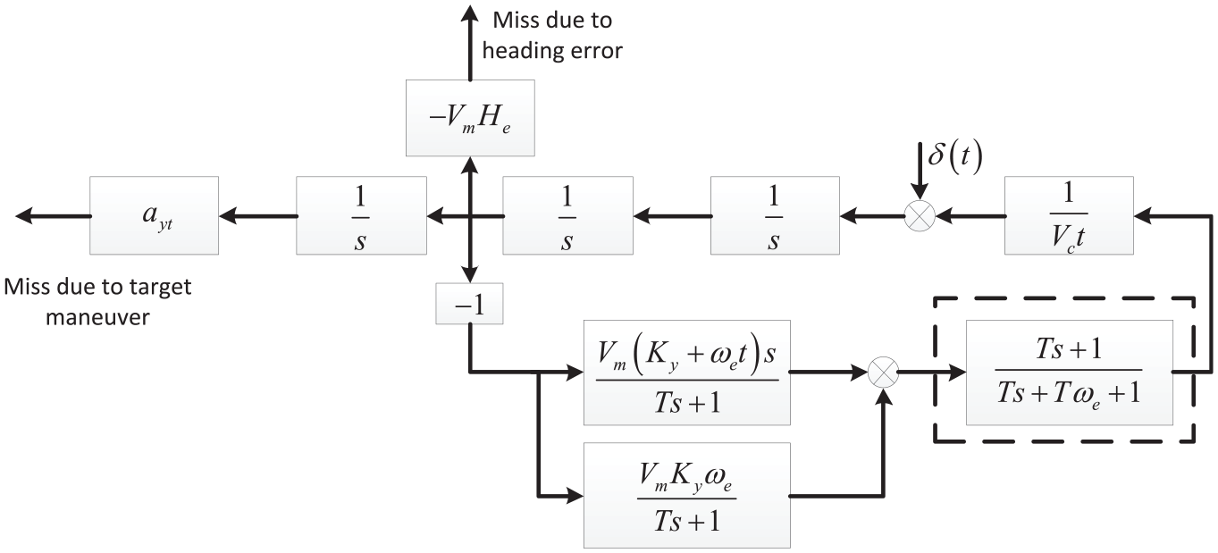
Adjoint of the homing loop.
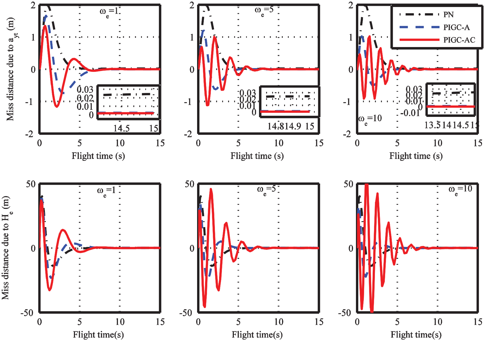
Miss distance with T = 0.5.

Miss distance with T = 1.0.
Suppose at some point near the impact, the open-loop guidance dynamics can be approximated as 5
and the loop transfer function of the entire guidance and control system with the two guidance laws can be obtained as
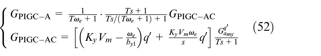
Assume that
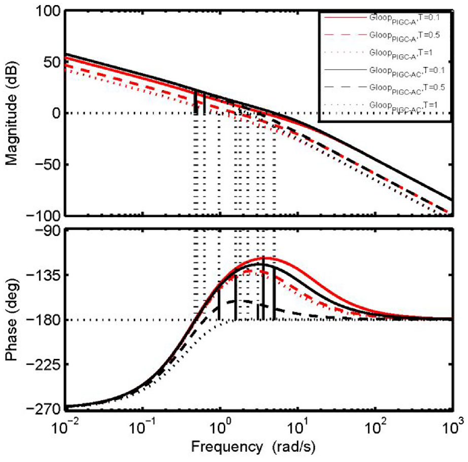
Frequency response of the guidance and control loop-gain transfer function.
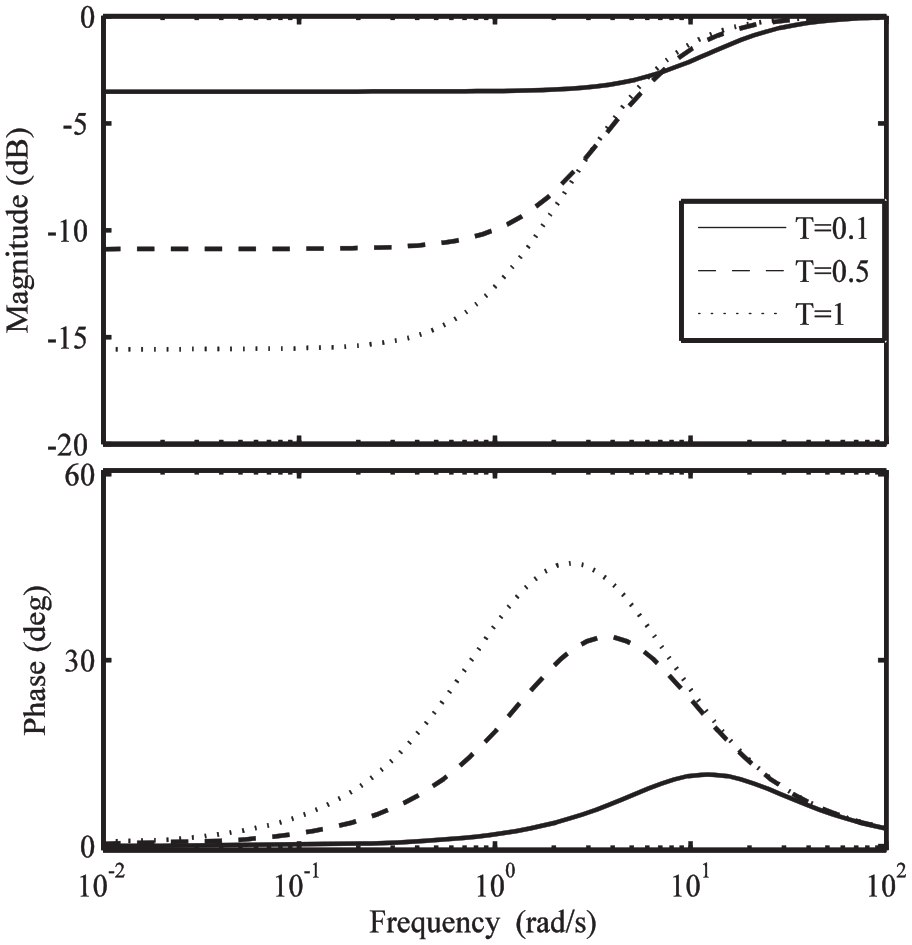
Frequency characteristics of the lead compensator.
Simulation result
As concluded in section “Comparison of two guidance laws,” the proposed PIGC-A is more advantageous in terms of the autopilot lag. Thus, numerical simulations are carried out in this section to evaluate the effectiveness of the proposed PIGC-A. When the seeker detects the surface target, the terminal guidance is initiated from a level flight state at the velocity of Ma 6. Suppose that the initial positions of the missile and the target are
The guidance and control parameters are selected as follows
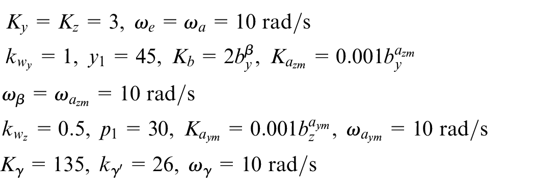
where
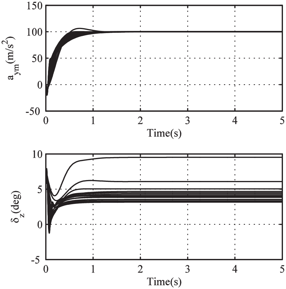
Step responses of the longitudinal acceleration for the characteristic points.
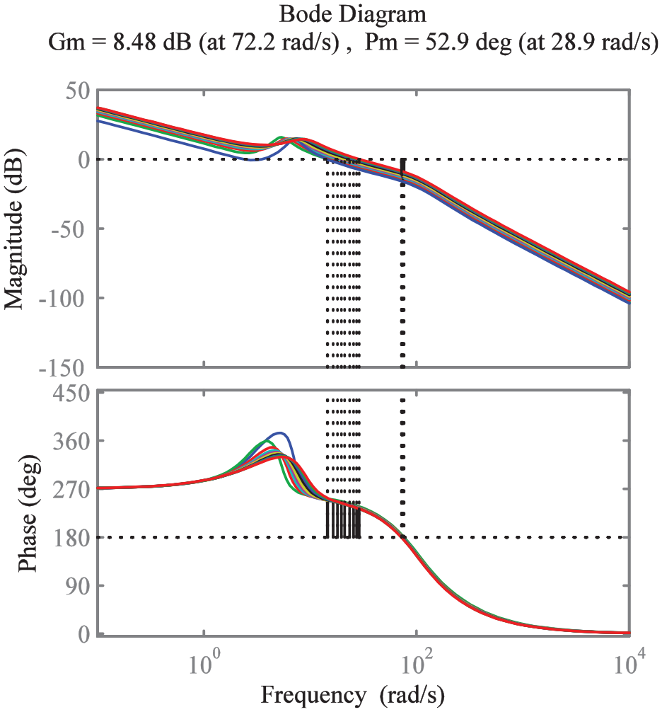
Loop transfer functions of the longitudinal acceleration control for the characteristic points.
Case 1
The objective of this case is to validate the robustness of the designed autopilot. All the aerodynamic forces are perturbed randomly at
3D trajectories with parameter perturbations.
Miss disturbances with parameter perturbations.
Simulation results for the relative range and missile velocity
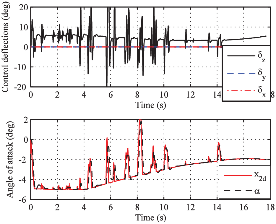
Simulation results for control defections and normal acceleration.
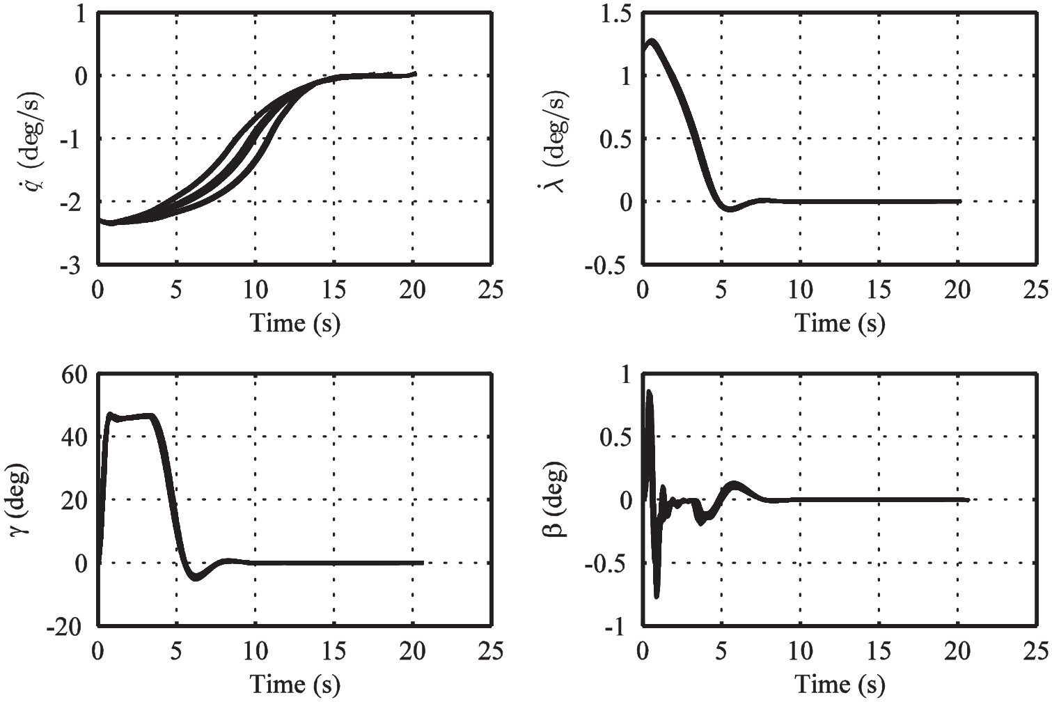
Simulation results for the LOS angular rates, roll angle, and sideslip angle with parameter perturbations.
Case 2
Suppose that the target is maneuvering with
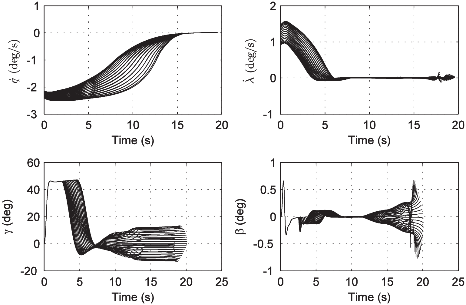
Simulation results for the LOS angular rates, roll angle, and sideslip angle with target maneuver.
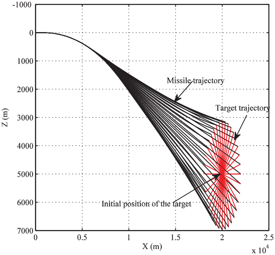
Top view of the 3D trajectories.
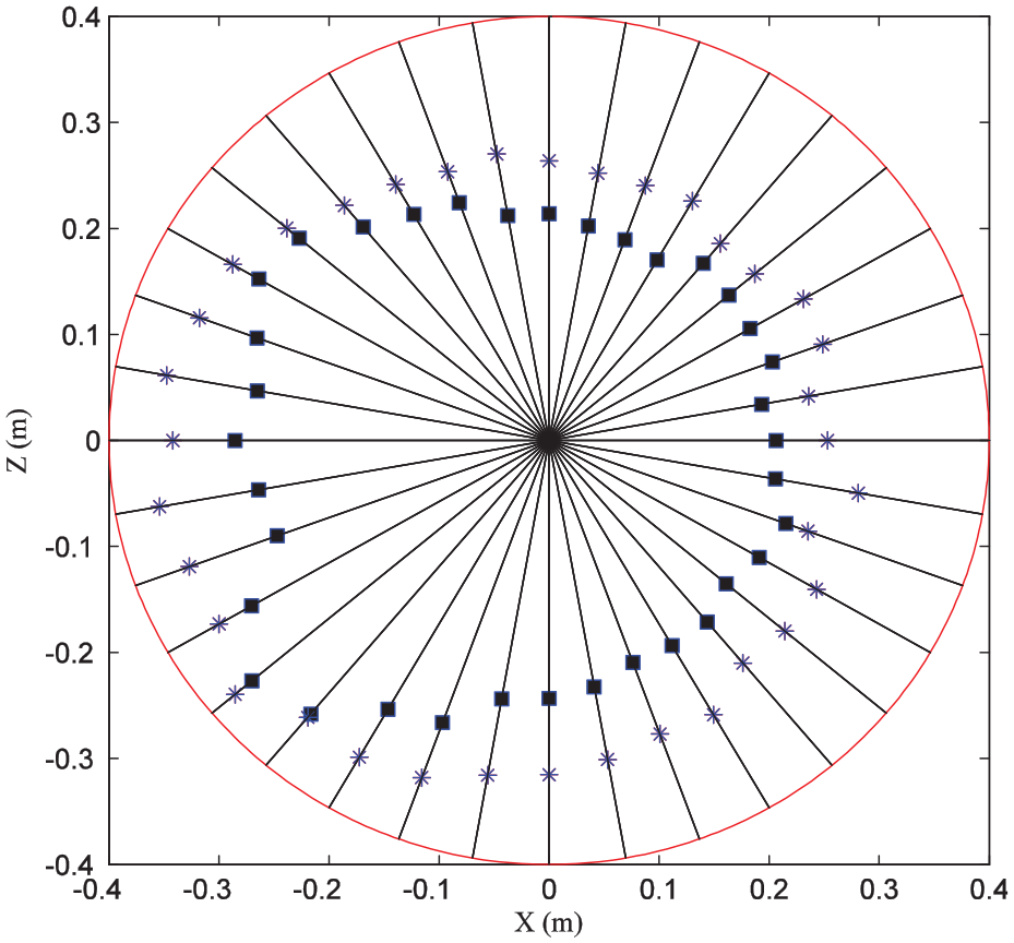
Miss distance comparison between the pure PN and the proposed method (blue star: pure PN, black square: the proposed method).
Case 3
Suppose that the target has a circular maneuverability and the velocity is 10 m/s. Different radiuses are considered, and they are set as 25, 50, 100, and 200 m, respectively. Note that the maneuverability of the target increases as the radius decreases. The miss distances for the PIGC-A and the pure PN are shown in Table 1. It can be seen that the proposed method can also outperform the PN guidance law for the circular maneuverability case.
Miss distances against the target with circular maneuverability.
PIGC: partial integrated guidance and control; PN: proportional navigation.
Case 4
In case 3, the PIGC-A is compared with the traditional separate design method. In this case, comparison is further conducted between the PIGC-A and other IGC methods. The back-stepping active disturbance rejection control–based IGC algorithm in Shao and Wang
19
is selected. The reason of selecting this method is that the ESO is employed as the main tool for disturbance rejection as done in the PIGC-A. Differently, this design is carried out in the back-stepping framework and high-order derivatives of the LOS angular rates are needed for control to prove the stability. When the seeker noise is considered, using high-order derivatives of the LOS angular rates may amplify the noise effect and thus degenerate the guidance precision. Consequently, seeker noise is included in this case. Since only the longitudinal plane guidance is considered in Shao and Wang
19
and the controlled variables in each design step are LOS angular rate, angle of attack, and pitch angular rate, respectively, the simulation for comparison also only considers the longitudinal plane guidance task to avoid the effect of the BTT and STT switching. In this case, the initial position of the target is
Seeker model with the noise.
Miss distance for the PIGC-A scheme considering the seeker noise.
Miss distance for the comparison scheme considering the seeker noise.
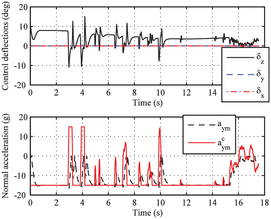
Simulation results for the control defections and normal acceleration with the seeker noise (PIGC-A).
Simulation results for the control defections and normal acceleration with the seeker noise (comparison algorithm).
Conclusion
In this paper, a PIGC scheme based on the RESO was proposed. For the guidance loop, the feedback linearization was utilized to decouple the kinematics between the two planes, and the reduced-order observer was designed to compensate the unknown target maneuver. When the autopilot lag was considered, two guidance laws (PIGC-A and PIGC-AC), wherein the input of the observer was the practical acceleration and the acceleration command, respectively, were compared using the adjoint analysis and the frequency domain analysis. It was found that the bandwidth and the phase characteristic of the guidance law in PIGC-A can adapt with the time constant of the autopilot. Therefore, the bandwidths of the guidance and control loop can be well matched and satisfactory damping can be achieved, which reflects the advantage of partial integration. For the autopilot design, angular rate feedback was performed first as conventionally done in practice for the pitch and yaw channels. Then, first-order LADRC was designed for the damping-enhanced dynamics, wherein the lumped disturbance including the time-varying dynamics, uncertainties, and coupling effects can be estimated by the RESO. Both the attitude angle (angle of attack, sideslip angle) and the acceleration (pitch and yaw accelerations) control can be designed in a unified framework in this paper. Extensive simulations were conducted to demonstrate the robustness and the high guidance precision of the designed PIGC-A.
Footnotes
Declaration of conflicting interests
The author(s) declared no potential conflicts of interest with respect to the research, authorship, and/or publication of this article.
Funding
The author(s) disclosed receipt of the following financial support for the research, authorship, and/or publication of this article: This work was supported by the Natural Science Foundation of China Under Grants 61573197, 61573199, 51777013, and 61603056; the South African National Research Foundation Under Grants 112108 and 112142; the South African National Research Foundation Incentive Under Grant 114911; and the Tertiary Education Support Program (TESP) of South African ESKOM.