
Abstract
The contribution describes the application of an Internet of Things device with an ESP32 microcontroller with the dual-core implementation of data processing and wireless communication. The first leading idea of using low-end hardware and software optimization to create software architecture in order to make the most of this hardware and reduce the cost of more expensive hardware solutions was tested. Our goal in architectural design was achieved. We created the basis of a general framework and defined its use scenarios, and then implemented these scenarios using components. This article describes the progressive development of our embedded vibration measurement testing system, on which we tested the individual software components for our framework. We created an application for our components using ESP32 processor cores, which divided the responsibility of these cores for the components of our framework.
Introduction
In this work, we will focus on the development of applications for devices available in the marketplace. We use an ESP32 (ESP-WROOM-32) chip from the producer Espressif and a cheap MCU9250 accelerometer. We use the traditional and accessible low-end modules available on the market as it is not our goal to get to the cutting edge of technology, but we aim to get the most out of modern technology to process and distribute measured data from an Internet of Things (IoT) module. The main objective is to design an application for an ESP32 chip that will use most of its capabilities. At the same time, we develop a general software concept that could be applied to any IoT device based on the ESP32 chip. The scenarios we propose are as follows:
Enabled device configuration;
Remote access;
Control and diagnostics of the device;
The maximum use of the HW capabilities of the device;
Enabled synchronization of multiple devices at the same time;
Multiplatform support for use.
These scenarios are implemented in the example of vibration measurements generated by the Brüel & Kjær vibration calibrator. For this vibration calibrator, we have placed a three-axis accelerometer, a gyroscope, and a magnetometer implemented on a single MCU9250 chip using our three-dimensional (3D) printed attachment. A detailed description of the components, architecture, and solution used is available in the following chapters.
After analyzing the scenarios of our design, we tried to build an embedded system architecture so that it was generic and could be reused to deploy other embedded systems. The scenarios that we have defined in the previous paragraph show us the implementation of components that characterize the behavior of an embedded system. Component names uniquely characterize the implemented scenario, provide network connectivity (Wi-Fi), communication with the parent control system (Message Queuing Telemetry Transport (MQTT)), data measurement using connected sensors and IoT modules, system monitoring (internal web server), and remote system reporting.
Our goal is to create architectural design patterns and methods for embedded systems that are linguistically independent and reusable, define the sustainability of a code, and logically help us implement any embedded systems. When searching for and creating patterns, we are inspired by the analogy of software development where these architectural design patterns are already used and serve as a universal language for software architects. At the end of the article, we summarize the architectural benefits and knowledge taken from the implementation of our embedded system.
Related works
IoT devices today are often those devices we have been using for years, but it had not occurred to us before that the miniaturization, digitization, and wireless communication technologies will enable us to make them into IoT. Typically, they are areas of the smart city equipment, smart home automation devices, i-health components, 1 wearable devices,2,3 embedded industrial solutions, and applications in military environment. 4 The IoT technology itself can be expanded with other concepts such as the Internet of Robotic Things 5 and nowadays almost the Internet of Anything. 6
The essence of the IoT device is therefore an electronic chip with the ability of wireless communication, whether it is Wi-Fi, BLE (Bluetooth Low Energy), LoRa, ZigBee, or other standards. At the present time, these communication standards are integrated into the chips of development boards without the need to connect to any other communication modules or shields. Some previous studies4,7,8 are devoted to the above-mentioned wireless technologies such as LoRa and ZigBee in an IoT environment, the use of standards itself is well described already in Yao et al. 9 and Lee and Huang 10 before the intense increase of using IoT devices.
When we defined our goals, we were inspired by publications defining the options and the course for the development of IoT applications 11 and by analyzing the practical use of the ESP32 family of chips. 12 The article describes ESP32 and differences from the ESP8266 predecessor as well as other chips and creates an application that tests the performance capabilities of the ESP32 chip and describes recommendations for deployability for IoT, highlighting dual core and FreeRTOS. We have tried to follow up and describe in detail the application and mainly architecture that uses dual core.
When designing the components and architectural solutions of our embedded system, we explored relevant articles dealing with the similar issues we faced, such as the implementation of a web server on an ESP32 device 13 or real-time communication and system management over the Wi-Fi network. These topics are covered in publications dealing with the development of IoT applications, protocols, and architecture of the IoT. 14 The article describes the IoT architecture in terms of the capability and use of communication protocols and standards with an emphasis on CTP (Communication Things Protocol) and IoT gateway. The article 15 devoted to the model of IoT interactions inspired us to create scenarios and requirements for application and generalization to embedded systems. Vibration monitoring using low-priced microcontrollers 16 is described by Atmel processor and another article 17 summarizes wireless communications in networks working with IoT modules. Related articles often deal with network architecture, protocols, and frameworks and describes limitations of traditional network architectures, 11 but the aim of our research is to develop software architecture. For the suitable design of the architecture, it was advisable to study some of the implemented cases of real projects. These articles are very interesting with similar themes and offer practical solutions for using IoT devices, including ESP32 chips.13,18 Both works use ESP32 chip and also implement web server, but single core is sufficient for the described application. We also point to the fact that web server implementation in our application is responsive. Experience with creating our own abstract software solution (framework) can also be found in the publication. 19
Another use and extension of IoT embedded system capabilities is cloud computing 20 as well as the Big Data perspective in connection with the concept of today’s Industry 4.0. 21 In the case of the industrial use of an IoT embedded system, where the number of measured data increases, it is necessary to use data analysis techniques such as machine learning and large data analysis to quickly analyze changes in device behavior. Previous publications21,22 are devoted to Big Data and Local Clouds themes. We implemented an MQTT communication standard, which is also used in the IoT application described in Masek et al. 23
The IoT modules used
The basis of the system is an ESP32 chip from the Espressif Company. ESP32 can perform as a complete standalone system or as a slave device to a host MCU, reducing communication stack overhead on the main application processor. 24 The chip includes an integrated Wi-Fi, Bluetooth, and other communication interfaces such as SPI and I2C/UART. A significant advantage that we use is the presence of two processor cores. Multiple vendor variants are available on the market, including Espressif ESP32S, ESP32-Wroom, LoRa ESP32, WeMos LOLIN32, and their clones. We have implemented the resulting solution on multiple boards, as the particular type of the board is not important, but is mainly a dual-core ESP32 chip.
We have used an MPU-9250 9DOF (nine-degree-of-freedom) sensor module in our application. This comprises a three-axis gyroscope, an accelerometer, and a magnetic field IIC implemented into a standalone chip. For all the three measured variables, it is also possible to switch ranges, and further properties can be seen during specification. 25
For vibration measurement testing, we have chosen the Brüel & Kjær 4294 accelerometer calibrator, which permits an accurate adjustment of measuring instrumentation at a standard acceleration level of 10 m s−2 (0–70 g load). In addition, a reference signal may be used for velocity and displacement calibration, at 10 mm s−1 and 10 μm, respectively. 26
The housing was designed and manufactured using a 3D printer for the resulting embedded system that will include a development board, a color 0.96″ organic light-emitting diode (OLED) 128 × 64 pixel display, an SD card, and connectors in the smallest size. A boxed version of the embedded system would include a cut-out for the power bank power supply connector, ventilation grid, and built-in calibrator attachment. We also created 3D printed holders for changing the position of the sensor in all three axes for the purposes of measurement testing. The embedded system will be remotely configurable from a superior system that can be a Notebook or Raspberry Pi (RPI).
The technology
To ensure that we have met the scenarios defined by us, we have decided to use the following technologies and apply them to ESP32 chip controllers. For the development of the ESP32 chip microcontroller, we have chosen the Arduino platform. The Arduino platform is an open electronic platform for development support on microcontrollers using a supplied development environment. As the Arduino platform natively does not support ESP32 microcontrollers, Espressif has developed support for this platform, known as the Arduino Core for the ESP32 Wi-Fi chip. 27 After installing this extension, it is now possible to develop it for ESP32 chip–based microcontrollers. The benefits of using the Arduino platform lie in the simpler prototype of software development for microcontrollers. Due to the fact that Arduino IDE does not support some standard features for development environments such as IntelliSense and source code administration, we have chosen to use the Visual Studio Code from Microsoft as a development environment 28 with an installed Visual Studio Code optional extension for Arduino. 29 Figure 1 shows the Visual Studio Code environment.
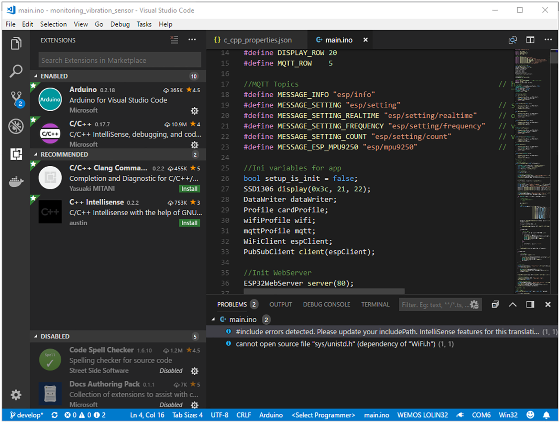
Visual Studio Code environment with installed ESP32 chip extension.
So far, we have been describing the definition of an environment for an application development on an ESP32 microcontroller. Now, let us find out what we get for components and libraries by installing the Arduino core for the ESP32 Wi-Fi chip. The most important extension library is the FreeRTOS kernel support. The FreeRTOS kernel is a real-time support implementation for microcontrollers, and all its specifications are described at https://freertos.org/. From our point of view, the implementation of FreeRTOS support for the ESP32 microcontroller is very important because it provides support for multitasking of the controller. We will use this support for our scenario implementation that maximizes the hardware potential of the device. Other interesting components that we use are an extended Wi-Fi support, SD card support, support for communication via the SPI or I2C standard communication interface, and so on. Thanks to this framework extension, we can use a standard third-party libraries installation system used in the Arduino platform. Another interesting type of technology that we use is the support for M2M (machine to machine) communication. This type of communication is used by IoT devices. We have chosen an MQTT communication protocol, developed and promoted primarily by IBM. MQTT is a simple TCP/IP (Transmission Control Protocol/Internet Protocol) communication protocol that allows you to transmit short messages on a publish/subscribe basis (see Figure 2).
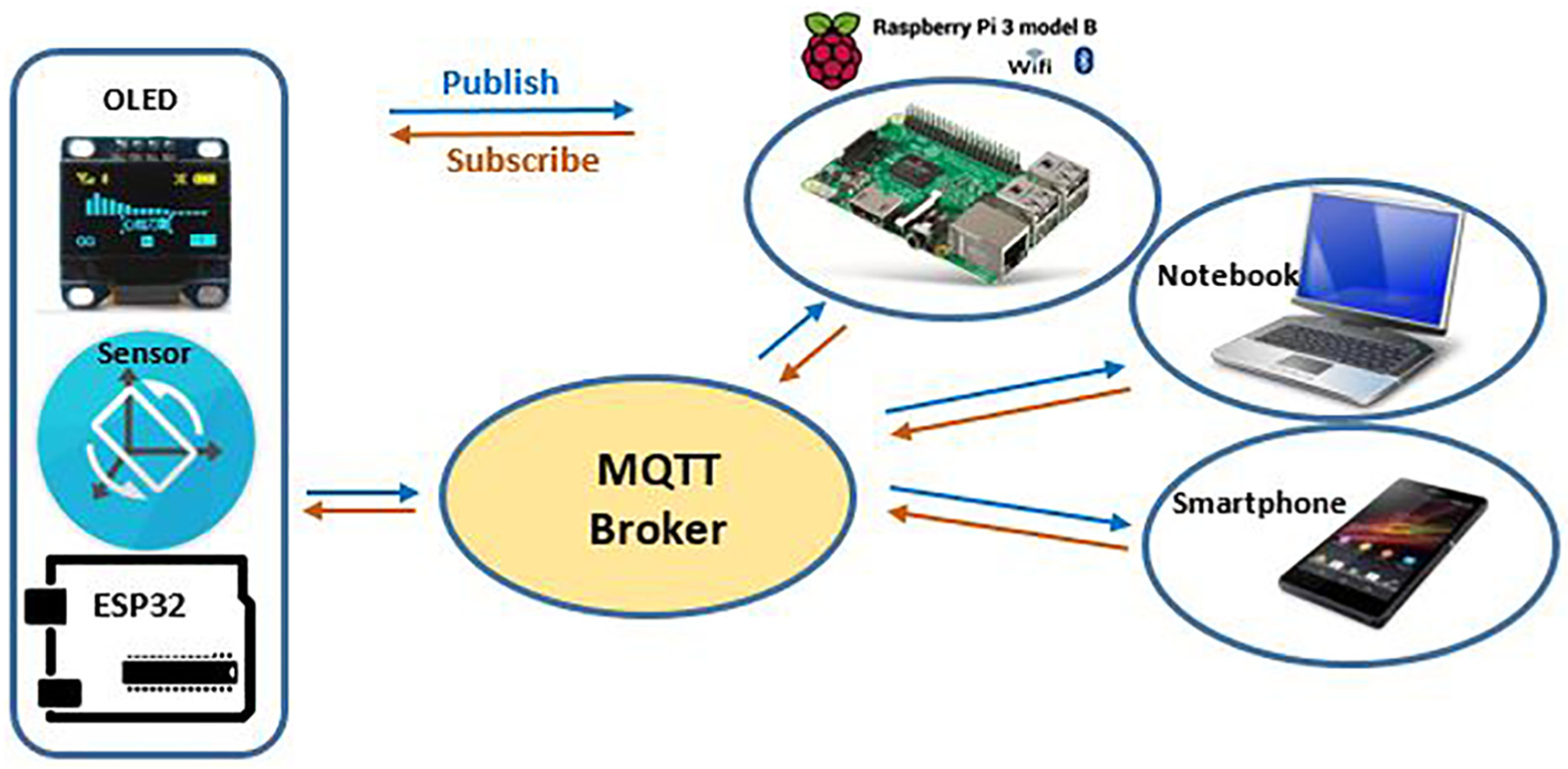
MQTT publish/subscribe model in our application.
MQTT is based on message transfer between clients through a central broker server. It mediates the communication by receiving a message from the provider (publisher) and then passing it to one or more readers of interest (so-called subscribers) to read it. One broker (journalist) can have many different publishers and many readers (subscribers), in which case the readers were given only the messages that each reader has subscribed to.
The transmitted messages are identified by the so-called topic under which the message value is stored. The message content itself is not defined and its representation is in the text or binary data system. The most commonly used format is JSON (Object Notation) and BSON (Binary JSON), but we are limited in our internal memory, so we have chosen a simple text that avoids excess formatting characters and we always have comprehensible messages. The configuration of this protocol is quite complex and all the options can be found in MQTT. 30
The design of the application architecture
In order to meet the scenarios defined by us, it is necessary to define the components that will be implemented for the given device. Figure 3 shows the layout and responsibility of the individual subsystems (components). A detailed description of component implementation is provided in section “Implementation on ESP32.” This section describes the main attributes and responsibility of the components.
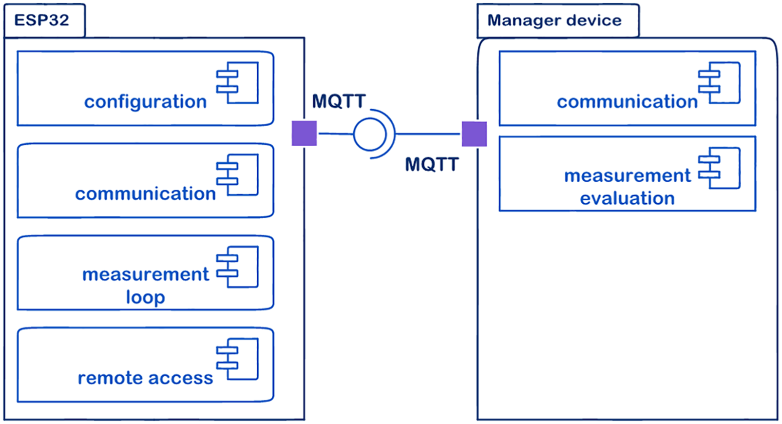
Application architecture.
The following components will be available on the ESP32 device.
Configuration
This component is responsible for the configuration of the required behavior of the ESP32 microcontroller. This component implements the device’s configuration scenario. The configuration is solved using *.json configuration files. These files are stored on the SD card in the desired structure. In our case, access to the Wi-Fi network is configured with WPA2 security and the broker is located for MQTT communication.
An example of the configuration file for Wi-Fi profile (wifi.conf) is as follows:
{
"ssid":"wifiSSID",
"password":"wifiPassword"
}
Example of configuration file for MQTT profile (mqtt.conf)
{
"server":"IP address MQTT",
"port":1883
}
Communication
This component is responsible for communication between the ESP32 board and the management device. Scenarios that are implemented by this component include the control and diagnostics of the device, the possibility of the synchronization of many devices at the same time, and multiplatform support for their use. MQTT technology is used for communication; see the chapter above. The synchronization scenario is solved by the MQTT broker which is responsible for sending the message to all devices; see the figure below. The following figure demonstrates the fact that we can control multiple microcontrollers from one management device. This fact is ensured by implementing a control and device diagnostics scenario. Scenario implementation is ensured by the subscription of specific messages for the microcontroller which triggers or diagnoses the device. If we use multiple ESP32 microcontrollers, each one must be identified with a unique identifier. The name of the client is used as the identifier. This implies that the client name is unique for each ESP32 device. The multiplatform application support scenario is secured by MQTT technology that is natively platform independent.
The list of communication messages, which are published from the ESP32 device, is as follows:
“esp/info”—this message provides an information log about ESP32 microcontroller behavior;
“esp/mpu9250”—this message provides real-time measured values from a particular ESP32 microcontroller.
The list of received messages of the ESP32 device is as follows:
“esp/setting”—possible values of the message
◯ start starts measurement of the connected sensor on a second ESP32 CPU core; ◯ restart restarts the ESP32 microcontroller; ◯ info shows information about the current configuration on the microcontroller display. The same information is sent via MQ then.
“esp/setting/real-time”—sets, whether the MQ message will be sent during measurement
◯ on—real-time data are sent from the microcontroller during the measurement; ◯ off—real-time data are not sent.
“esp/setting/frequency”—number of tics for CPU interrupt, for which the default value is 5;
“esp/setting/count”—number of samples for one measurement, for which the default value is 5000.
Remote access
The component is responsible for accessing the ESP32 device and enables the measured data to be stored on an SD card. This is how we implement a remote access scenario. Access to data is solved via the web server interface running on the ESP32 device. For us, the remote access scenario serves primarily as the access to backup data measured and stored on the SD card due to the occurrence of a real-time failure of communication during measurement. Figure 4 shows a web server preview on an ESP32. The web server also provides display configuration information and gives real-time values such as the CPU temperature. The web server is created using a responsive design.
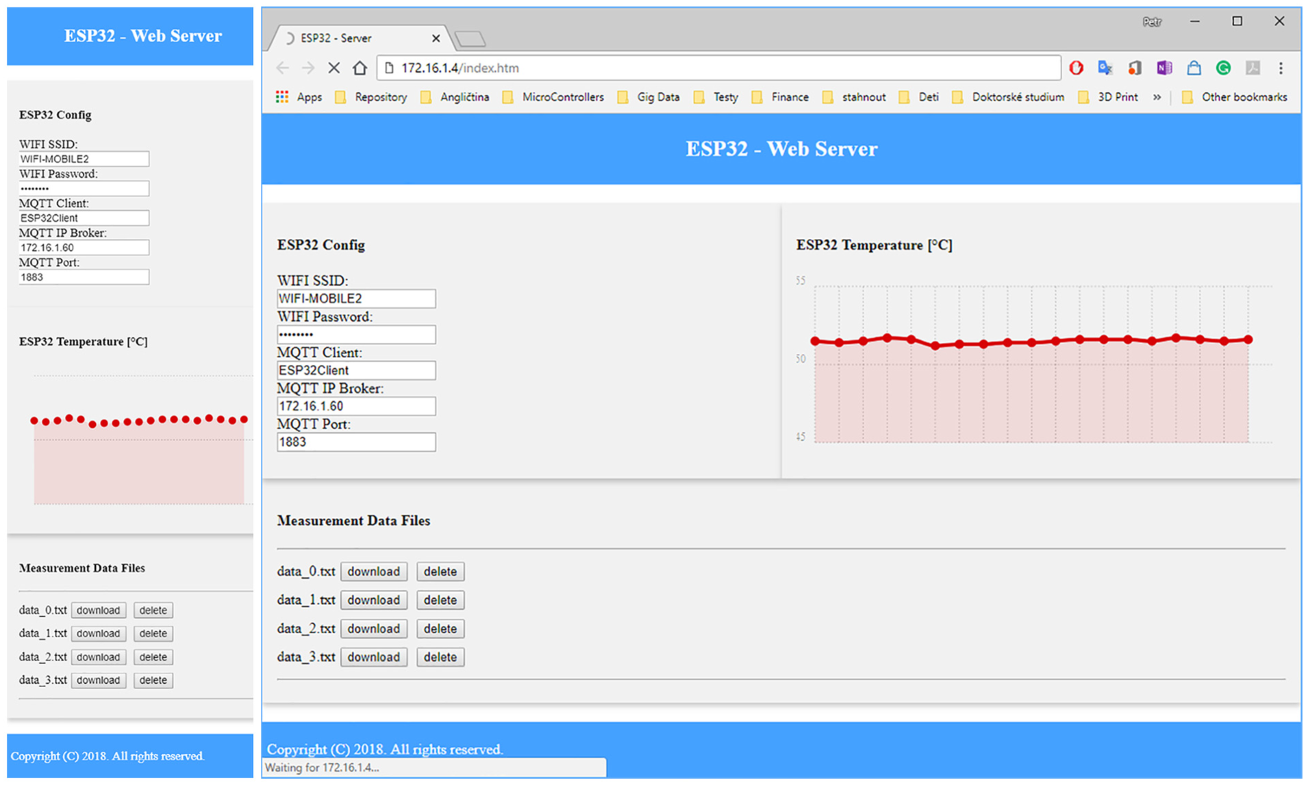
Web server on a mobile device (left) and on a laptop or Raspberry Pi (right).
For a manager device, the following components are necessary.
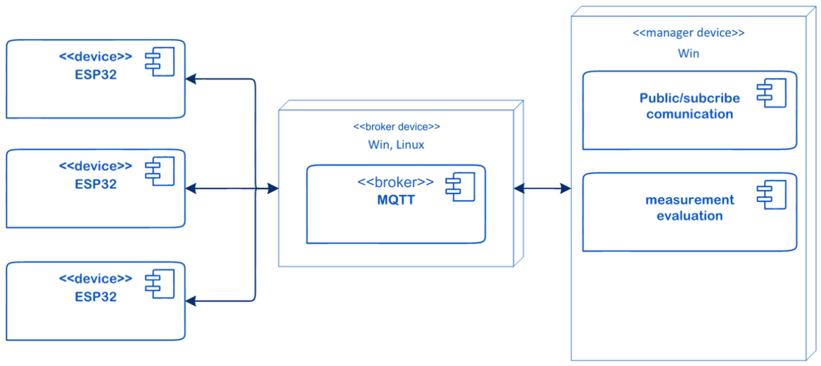
Measurement loop
This component is responsible for the implementation of the source code of the measurement loop function on an ESP32 board. This component implements the scenario of maximum hardware usage of the device. The ESP32 microcontroller board has two cores, so one core is dedicated to the measurement loop, while the other is dedicated to the communication. This functionality is possible thanks to the FreeRTOS interface support for the ESP32 board, which enables multitasking and possibility of natively running a task on a particular core.
Communication
This component is responsible for communication between the main manager device and particular ESP32 devices (see component “communication”). Figure 5 shows the communication of a management device with “n” ESP32 boards.
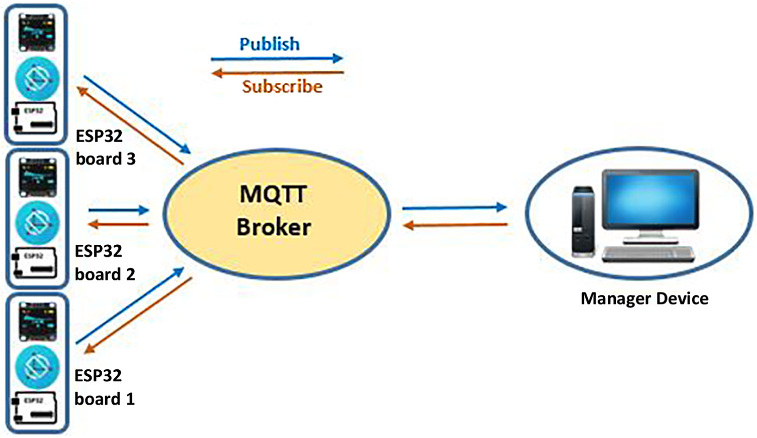
MQTT communication model for three ESP32 boards.
Measurement evaluation
This component serves for better and easier work with ESP32 modules in a control device environment such as a PC or another operator’s superior device (Figure 6). We have developed for this support a Windows-based platform software, which serves for quick evaluation of the measured values and also for the control of the ESP32 device (see Figure 7). The future intent of components working on the side of a management device is the creation of a tool that is independent of the platform; therefore, we will achieve the benefits of deployment variability in different environments.
An independent operational system communication model.
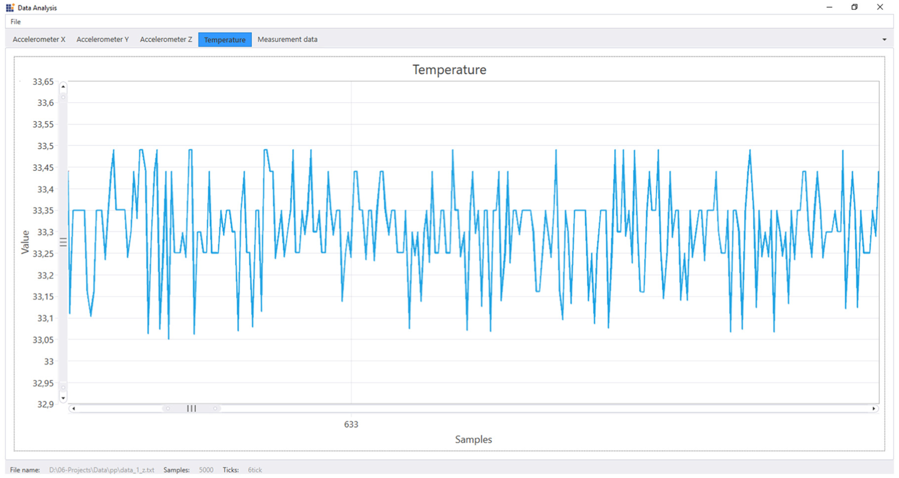
Windows application—temperature measurement on an ESP32 board (5000 samples).
Implementation on ESP32
The implementation of the described scenarios with the defined components is created using the Arduino platform. For uncomplicated implementation and reusability, we have created the following program components:
The Profile component—a class that is used for getting the configuration stored on the SD card. In our case, we gain a configuration of Wi-Fi connections and MQTT connections.
The DataWriter component—a class that puts together the job of writing the measured data on an SD card. The class encapsulates the API supplied by the Arduino core interface for the ESP32 Wi-Fi chip.
The CustomDisplay component—a set of auxiliary functions for working with an OLED display.
The Esp32Sensor component—a class that encapsulates access to integrated sensors on the ESP32 board.
The MPU9250 component—a class that encapsulates the access to the MPU9250 module via the SPI interface. This class encapsulates access to the gyroscope, accelerometer, magnetometer, and temperature sensor.
Thanks to these created components, it is possible to divide the responsibility of the individual program activities and ensure easier debugging of the source code. Programs for microcontrollers based on this Arduino platform, as are customary, have two basic functions, namely, Setup() and Loop(). The initialization of the variables and the sensor is executed in the setup function at the startup of the program (by switching on the microcontroller supply), and the application logic is performed in the loop function.
In our program, the most important feature of the setup function is the initialization of the MQTT client. This section registers the callback function “callback_mqtt,” which is responsible for processing prepaid MQTT messages. Another interesting initializing function is for the web server. This function defines the routing of the web server. An important fact is that the setup function is performed on ESP32 chip core No.1 and only once when the ESP32 microcontroller is started. The left side of Figure 8 shows the activity diagram of the setup function.
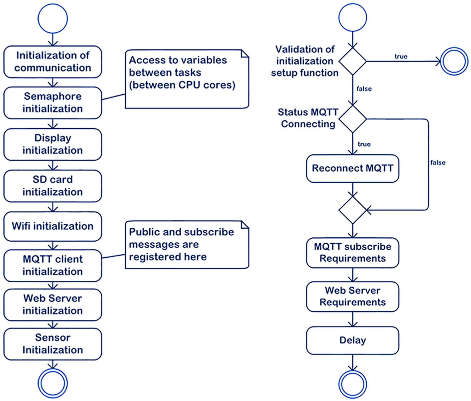
Activity diagram for setup (left) and for loop (right).
The loop function is also performed on ESP32 chip core No. 1. This feature provides the receiving algorithm for message processing that comes from the MQTT broker. If the connection to the MQTT broker is lost, the connection will automatically be restored in this loop. The other messages that are accepted in this part of the code are for the web server component. These are the standard HTTP communication messages. The loop function runs on the microcontroller repeatedly in a loop during the running of the microcontroller. The most interesting part of the source code on the ESP32 microcontroller is the callback function, which processes the incoming messages from the MQTT broker. Figure 9 shows a passing through the callback function. This function handles only the incoming MQTT messages.
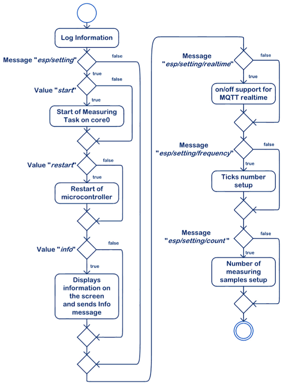
Activity diagram of the MQTT callback function.
The previous activity diagram shows the activity which calls the measuring function. This activity runs on the second core, which is dedicated to this activity only. Figure 10 shows this process. In the next chapter, we will look at the practical testing of the implemented microcontroller.
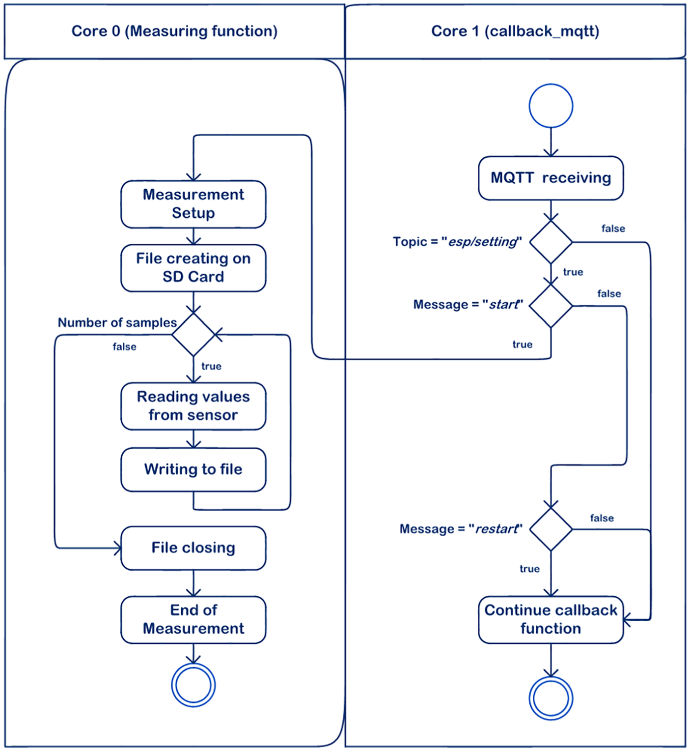
Activity diagram of the dual-core processing of a measuring function.
Testing of ESP32 implementation
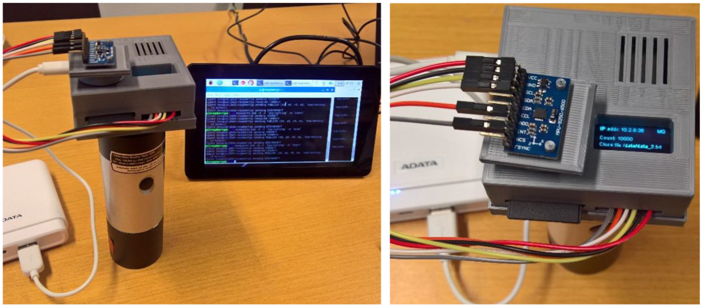
In the previous chapter, we focused on the design and creation of the embedded system, and in this chapter we will describe the testing of the system under laboratory conditions. Figure 11 shows the prototype of our embedded system. As shown in the figure, the connected display acts as a status indicator and shows the readiness of the system, according to the required environmental configuration. For complete system readiness, it is necessary to connect the system to the Wi-Fi network and the MQTT broker.
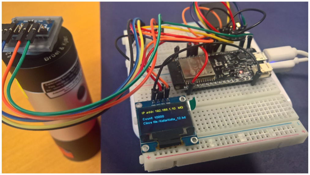
Measurement on an unboxed prototype.
It can be seen from the left side of Figure 12 that the system has joined the Wi-Fi network and has been assigned an IP address (yellow text identification), as if just trying to join the MQTT broker. If the system connects to the broker, an MQ character appears in the status bar (yellow text) in the top right corner (as shown in Figure 11). If the connection timeout expires, it is necessary to reconfigure the MQTT broker setup. After successful connection, which depends mainly on the system configuration, the system can now be managed using MQTT messages. The right side of Figure 12 shows a particular measurement configuration. These values are set using MQTT messages. Subsequently, the MQTT message is triggered by the measurement. Figure 13 shows vibration measurements on the embedded system prototype. Once the measurement is complete, a message is sent to the MQTT broker where the measured data are stored. The same information as sent by the MQTT is also displayed on the board mounted display. After successfully testing the unboxed prototype, we could design an encapsulating version of the entire system into a boxed version.
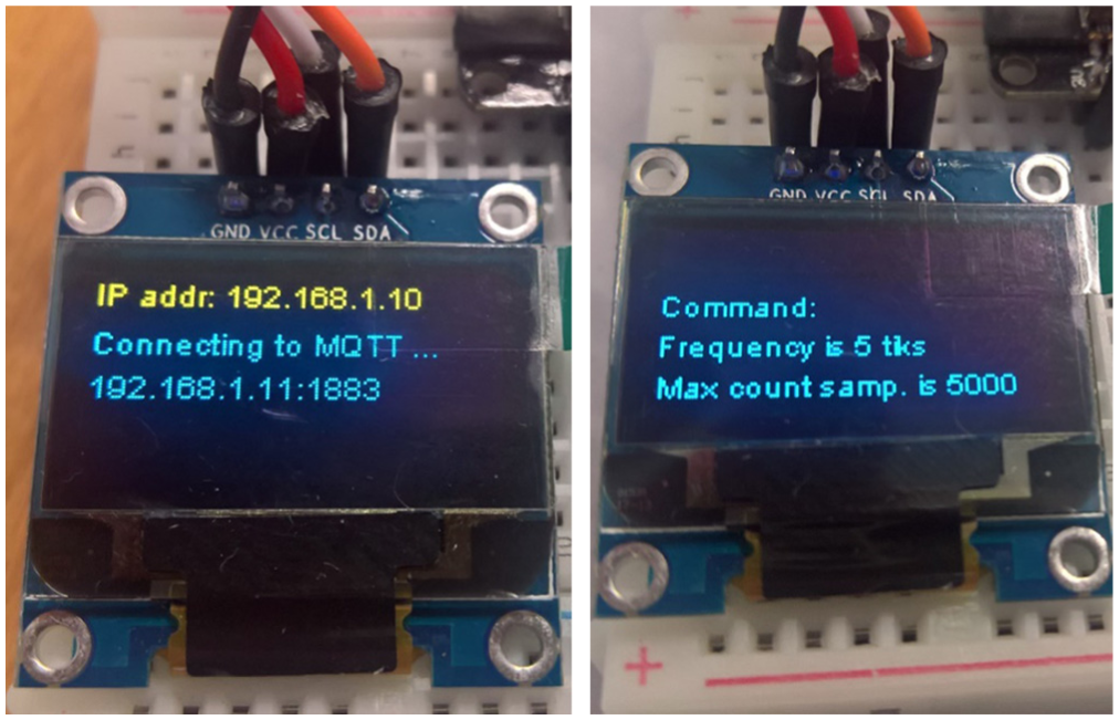
IP address assignment and connecting the MQTT (left) and reading configuration for the measurement (right).
Boxed testing embedded system with a wireless MQTT configuration from Raspberry Pi (left) and a detailed view of an embedded system mounted on a BK calibrator (right).
Figure 13 shows a boxed variant of our embedded system with scenario implementation of an MQTT broker installed on an RPI. The power supply is designed using a power bank. Figure 14 shows the created software itself that shows the measured data from all the sensors in clear tables; in our example, we showed 5000 values for the 9DOF sensor + temperature, thereby 50,000 values at the current MQTT setting. We can change this setting with a common configuration, as noted above. Figure 15 shows the holders for all three testing dimensions for the x, y, and z axes. These holders are created using a 3D printer and serves for a precise comparison of the vibration measurement results using a 9DOF sensor for all the axes (Figure 15).
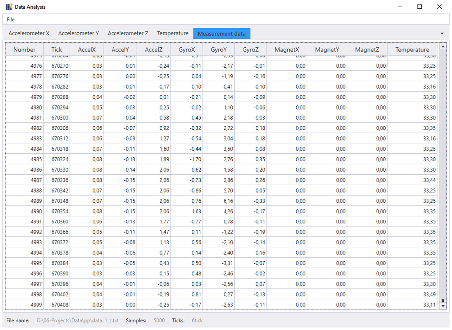
Data analysis software for processing the measured values—5000 samples.
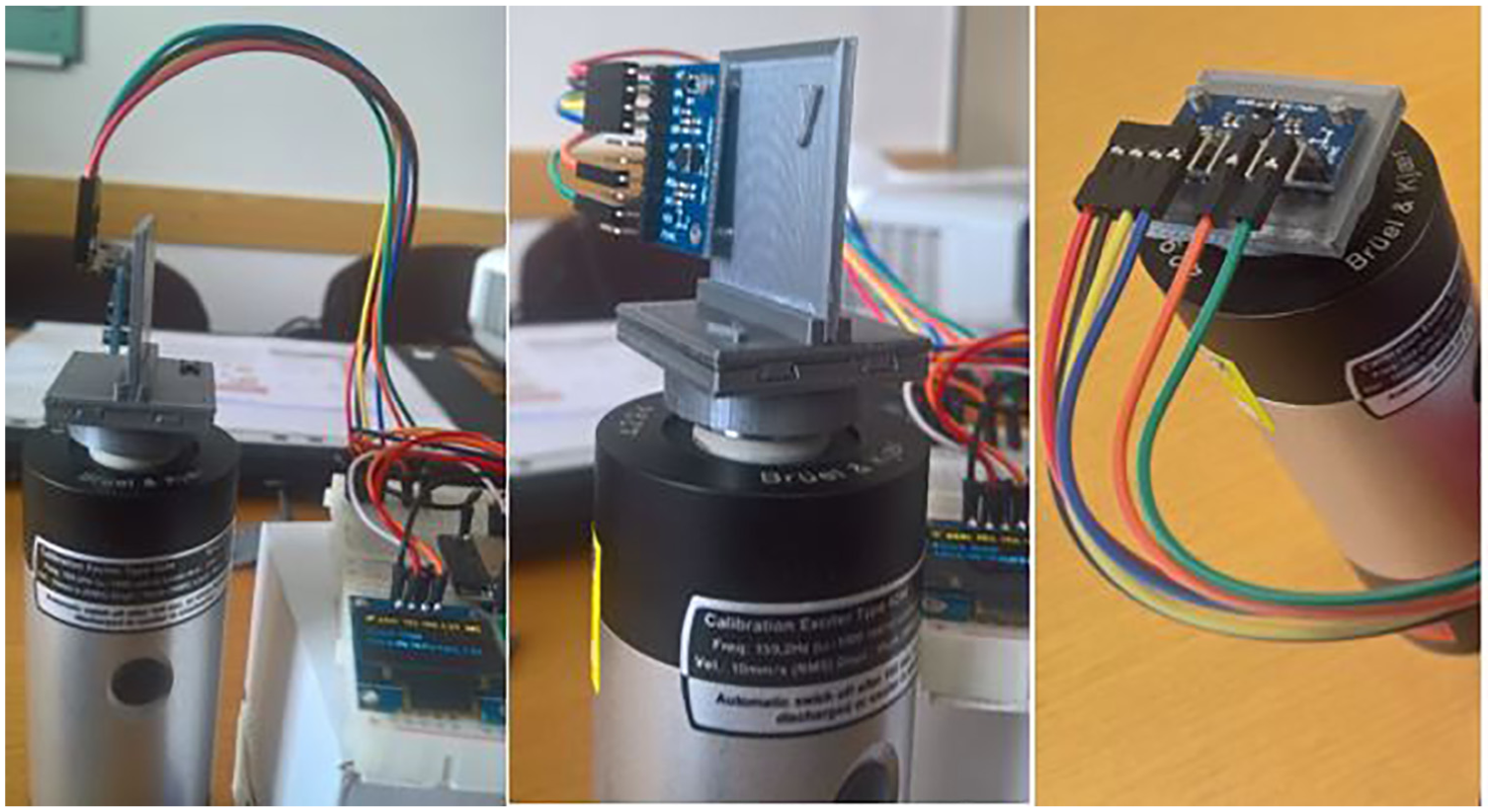
Testing accelerometers at the orthogonal positions for the x, y, and z axes.
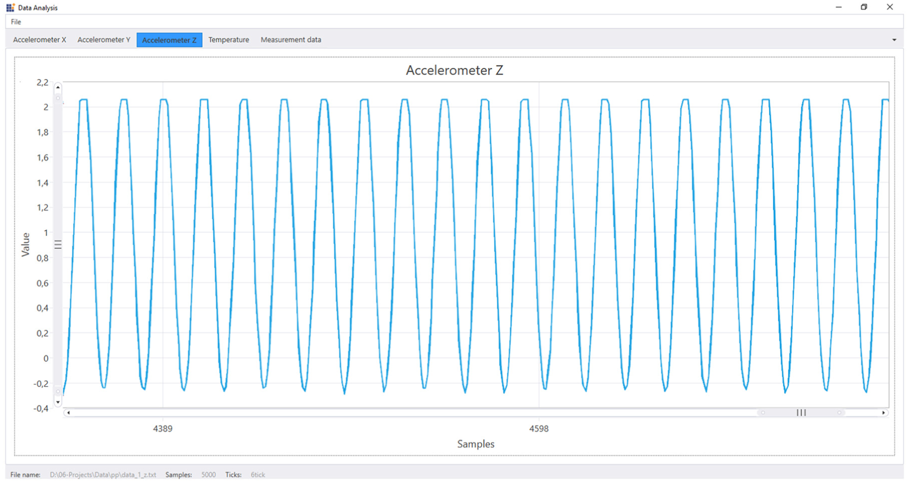
Measured values from the BK vibration calibrator—measuring test for 5000 samples.
Conclusion
Our goal was to identify the possibilities of low-end IoT devices and to get them into context with up-to-date technology and equipment that are used in industrial practice. As a representative of these low-end devices, we have chosen the ESP32 microcontroller, which has built-in Wi-Fi connectivity with support for standard security such as WFA (Wi-Fi Alliance), WPA (Wi-Fi Protected Access)/WPA2, and WLAN Authentication and Privacy Infrastructure (WAPI). 24 Furthermore, the ESP32 microcontroller supports two computational cores and therefore allows us a full parallel approach for application design, contrary to another microcontroller, for example, ATMEL microcontrollers that have only one computational core and a pseudo-parallel task. We also created the proof of concept of the general software architecture on the ESP32 chip. With this architecture, we have demonstrated the scenarios defined by us and have tested this proof of concept in a real example of vibration measurement. In the architectural design, we focused on the possibilities of development from the point of view of sustainability of source code and its testability and reusability. We have realized these architectural qualities using individual components that have a clearly defined use responsibility. We chose the Arduino platform as a development environment, into which we have installed ESP32 development support. The first release of the ESP32 support was officially released on the Arduino platform at the time when we finished this article. We proceeded to design each scenario separately and then test the functionality of the components. We linked the scenarios into an architectonic design after debugging the individual components. The biggest problems were the implementation of the dual-core performance layout and the ability to work with the SD card. After completing the entire architectural solution on the ESP32 chip, we performed the testing of the entire embedded system in a laboratory environment. We focused on the following functionalities during testing:
Testing of a large amount of data writing (1000 to 100,000 samples) on an SD card with different RTOS interrupt configurations. The sampling is limited to 1 kHz, which is not the boundary range of the vibration sensor, but is the range of the interrupted frequencies of the RTOS system running on the ESP32 chip. Data storage is designed for backup in the case of communication failure.
Testing of the remote configuration of the ESP32 chip with different settings of the measurement values (sampling frequency, expected number of samples).
Testing of real-time measurements while delivering the measured values through the network. We have taken advantage of buffering the measured values in ESP32 chip memory with this solution and optimized the amount of data transmitted over the network. We have used RPI as an IoT hub for real-time data collection. We chose RPI due to a reduction of the costs of the overall embedded system and control device solutions. We have verified the reusability of some components, such as communication, persistence, and system configurability during the development of the embedded system.
For complete verification of the generality of the architectural design on the ESP32 chip, several tests need to be made to equip different new ESP32 development boards. We will focus on this aspect in the future. The first board which we have tested is the board TTGO TS v1.4, where the same set of sensors as in our sample solution is used on one board. Thanks to the dimensions of the board and the all-in-one design of the board, this board is ready for testing as well as for industrial environments. We want to implement sophisticated diagnostics using cutting-edge computing on RPI and evaluate them on an ESP32 chip in the near future.
The knowledge of the general architectural design that we obtained, and at the same time verified during the implementation of the real example, can be evaluated from several perspectives:
We have verified the entire development cycle for deploying a relatively new ESP32 microcontroller, which is gaining increasing popularity and application in the field of IoT applications. The fact that the ESP32 microcontroller has two separate cores is considered to be a great advantage, so our architectural design can natively work with the idea of parallel processing. The chip used with the ESP32 microcontroller can be compared to the processors that are used in the PC from the point of view of the architectural design application. This uses the FreeRTOS system interface that gives us the ability to work in tasks. FreeRTOS can be considered a lightweight version of an embedded development system. On the other hand, ESP8266 chips use one kernel and pseudo-parallel processing occurs when implementing FreeRTOS tasks. That is why ESP32 gives us a big advantage in real-time processing. The behavior of the FreeRTOS interface that implements such processing had also been verified on other chips like ATMEL, where the use of one kernel cannot provide native real-time behavior. The triggering of individual tasks is controlled by their priority. We must consider that the task with the highest priority should be assigned to program execution to avoid blocking functionality, and therefore measuring tasks have a lower priority and can unexpectedly be blocked. This situation does not occur with dual-core chips, where one measuring task can be assigned to one kernel and the execution of the program to the other kernel, which we have used in our architectural design solution.
We have created a reusable architecture that can be used to develop other embedded systems. We can use this architecture to deploy the ESP32 chip when measuring and processing data from different sensor types. In our sample application, we chose a nine-axis accelerometer and temperature sensor to show data processing of ten measured variables at one time. We can integrate the embedded system with other types of sensors for measuring physical variables; our reusability architecture will not change and only the measured variables will be of another type.
The architectural design is based on the simplicity and responsibility of the components that only handle their own functionalities. The application development with design patterns for desktop and web applications works in the same way. We have been inspired by these patterns and have tried to convert the architectural design into an embedded system that works with IoT technologies. One of the biggest problems we have addressed is that the development of embedded systems is usually based on procedural programming, while design patterns use an object-oriented approach. This issue needs to be further elaborated and adapted to possible solutions for procedural solutions. At the same time, we are trying to bring some principles from the point of view of SOLID principles such as, for example, the following:
◯ Single Responsibility Principle: In other words, each component should be responsible for just one thing that should be clearly explained by its name.
◯ Open-Closed Principle: Components should be opened for extending but closed for changes. Extending the functionality of the components should only be possible by adding a new code without having to interfere with the existing code.
◯ Interface Segregation Principle: More specific interfaces are better than one universal interface. Components should depend only on the interfaces they use. If we define only one large interface, we lose an overview of which parts of the interface are being used. When changing the component interface, we must always review and, if necessary, modify all of its use.
Other principles of SOLID architecture are difficult to implement in the embedded world and will be dealt with in subsequent research.
Architecture is universal and independent. We are independent of both the programming language and the development platform. We can develop the resulting applications in a variety of ways, and often depending on advances in technology, debugging development tools, and implementing specific header functions at the source code compilation level. If, in some emerging development platform, the performance of library functions is tuned to resolving dependencies, we can move to a different development platform without reworking the entire philosophy of the application. We can choose to develop them under Windows or Linux, and the transition between systems will not be painful; on the contrary, we can tailor the application to the surrounding ecosystem. We can choose to change the parent system between the PC, laptop, industrial PC, a Raspberry type of computer or other devices without changing the architecture.
Application architecture is not supposed to be complex in nature, its main goal is to create an application that can be tested and is sustainable in the long run and capable of implementing new functionality without losing its current behavior. That is why we have defined in our architectural design the individual components (subsystems) that have clearly defined their own responsibility (remote access, communication, and configuration). This implies that they are simply testable and maintainable. Extending such designed applications is not challenging and the application is ready for future changes without losing its sustainability and testability.
Footnotes
Declaration of conflicting interests
The author(s) declared no potential conflicts of interest with respect to the research, authorship, and/or publication of this article.
Funding
The author(s) disclosed receipt of the following financial support for the research, authorship, and/or publication of this article: This work was supported by the European Regional Development Fund in the Research Center of Advanced Mechatronic Systems project under project no. CZ.02.1.01/0.0/0.0/16_019/0000867 within the Operational Program Research, Development and Education.