
Abstract
With the development of computer technology and three-dimensional reconstruction technology, three-dimensional reconstruction based on visual images has become one of the research hotspots in computer graphics. Three-dimensional reconstruction based on visual image can be divided into three-dimensional reconstruction based on single photo and video. As an indirect three-dimensional modeling technology, this method is widely used in the fields of film and television production, cultural relics restoration, mechanical manufacturing, and medical health. This article studies and designs a stereo vision system based on two-dimensional image modeling technology. The system can be divided into image processing, camera calibration, stereo matching, three-dimensional point reconstruction, and model reconstruction. In the part of image processing, common image processing methods, feature point extraction algorithm, and edge extraction algorithm are studied. On this basis, interactive local corner extraction algorithm and interactive local edge detection algorithm are proposed. It is found that the Harris algorithm can effectively remove the features of less information and easy to generate clustering phenomenon. At the same time, the method of limit constraints is used to match the feature points extracted from the image. This method has high matching accuracy and short time. The experimental research has achieved good matching results. Using the platform of binocular stereo vision system, each step in the process of three-dimensional reconstruction has achieved high accuracy, thus achieving the three-dimensional reconstruction of the target object. Finally, based on the research of three-dimensional reconstruction of mechanical parts and the designed binocular stereo vision system platform, the experimental results of edge detection, camera calibration, stereo matching, and three-dimensional model reconstruction in the process of three-dimensional reconstruction are obtained, and the full text is summarized, analyzed, and prospected.
Introduction
Vision is the most important sense organ of human body, and 80% of human information is obtained by vision. 1 Computer vision originated in 1982. Professor Marr of MIT first combined information processing with mathematics, physics, neurobiology, and other disciplines in the artificial intelligence laboratory, 2 and put forward the original framework of computer vision system, 3 –5 which makes the computer vision system have a complete system. Later research is based on this theoretical system to enrich and expand. The core purpose of computer vision is to make the machine have the same function as human vision and can sense, acquire, and analyze the surrounding environment. At the beginning, people used three-dimensional (3D) drawing software to build the 3D model of the object, 6 but this method is time-consuming and labor-consuming, and the accuracy is difficult to guarantee. Therefore, researchers began to explore how to use the existing real object information to build the 3D model of the object. 7,8
With the development of computer graphics in 3D visualization, all kinds of 3D reconstruction technologies based on computer technology have made great achievements, and the application of real-time interactive 3D virtual reality system has been expanded and popularized. 9 As the most important distance sensing technology in passive ranging method, stereo vision directly simulates the way of human vision processing scenery and can measure the stereo information of scenery flexibly under various conditions. Its function is irreplaceable by other vision methods. The research on it is of great significance both from the perspective of visual physiology and in engineering application. In the past, stereo vision was mainly used in robot vision detection and navigation. 10,11 With the development of science and technology, our requirements for 3D information are more prominent, especially in the fields of medical treatment, automobile, living tree reconstruction, digital city, aviation, and other fields. 12 According to the different application areas, the technologies adopted are also different. Image-based 3D reconstruction is to extract 3D information of objects from 2D photos, which is a 2D-3D dimension upgrading process, 13 –15 calculate the depth information of objects according to some known information in 2D images and recover the 3D shape of objects. 16 The 3D reconstruction based on photos can be divided into 3D reconstruction based on a single photo and 3D reconstruction based on two or more photos. This method requires relatively simple conditions. Only two-dimensional (2D) photos of the object can be provided to obtain the depth information of the object, 17 and the 3D structure can be reconstructed, which is widely used in film and television production, cultural relic restoration, mechanical manufacturing, 18 medical, and health fields. It has a very attractive application prospect. At present, in the research of 3D reconstruction based on 2D image, shape from shading method is simple and direct, but it has many constraints and can only be applied under laboratory conditions, which greatly limits its development. 19 Patelfly et al. made a series of improvements on the basis of Vetter and Blanz methods. Combined with the advantages of SFS and 3D morphable model (3DMM) methods, they proposed an error evaluation method based on linear optimization for fusion of geometric and surface normal errors, which improved the accuracy and efficiency of 3D model reconstruction to some extent. 20,21 The disadvantage of 3DMM algorithm is that it needs a priori 3D face database information, and the reconstruction process is computationally expensive and time-consuming. 22 In addition, although the 3DMM method has a good global accuracy, the reconstruction accuracy of some detail areas highlighting face characteristics is not ideal. 23,24 Jiang Dalong et al., Institute of computing technology, Chinese Academy of Sciences, proposed an algorithm to reconstruct 3D face data from 2D face photos. The algorithm only needs a single front face photo, on this basis, it can quickly reconstruct a specific 3D face model. It uses the feature point location technology of 2D face photo and the statistical learning method of 3D face model, which has strong innovation and practicability. At the same time, this algorithm can also be applied to face recognition, which can improve the accuracy of face recognition to a large extent; the disadvantage is that the accuracy and authenticity of the reconstructed 3D model need to be improved. 25,26
A complete stereo vision system based on 2D image can be divided into image processing, camera calibration, stereo matching, 3D point reconstruction, and model reconstruction. The purpose of image processing is to eliminate the influence of various adverse factors on the image acquired by the camera, so as to obtain the image that can reflect the original scene most truly and to prepare for the subsequent feature extraction and matching work. 27 –29 This includes the feature extraction of the image. Feature extraction is to get the image features that match. At present, the commonly used matching features mainly include point feature, line feature, and region feature. 30,31 Generally speaking, large-scale features are rich in image information, and there are few in the image, so it is easy to get fast matching. However, their positioning accuracy is poor, and feature extraction and description are difficult. However, the number of small-scale features is large, and the information contained in them is small, so a strong constraint criterion and matching strategy 32,33 are needed to overcome the ambiguity matching and improve the efficiency of operation. Good matching features should have the ability of distinguishing, invariance, stability, uniqueness, and effectively solving the ambiguity matching. 34
Proposed method
2D image preprocessing
The purpose of image processing is to eliminate the influence of various unfavorable factors on the image captured by the camera, so as to obtain the image that can truly reflect the original scene and to prepare for the subsequent feature extraction and matching work.
Image grayscale
The gray-scale method of image is that the image captured by camera is color image, and the subsequent feature extraction, matching, and other processing are gray-scale images, so it is necessary to transform the color image into gray-scale image. There are mainly three ways to grayscale.
1. The maximum value method makes the value of R, G, and B components equal to the largest of the three values, namely

2. The average value method makes the value of R, G, and B components equal to the average value of three, that is

3. The weighted average method assigns different values to R, G, and B components according to their importance, and makes the values of the three components weighted average, that is

Among them, WR , WG , WB are the weights of R, G, and B components, respectively. The different gray-level images can be obtained by different values, when R = G = B = 0.30R + 0.59G + 0.11B, and the most reasonable gray-level image can be obtained.
Figure 1 is the original image, Figures 2 to 4 show the gray image obtained by three gray-scale algorithms, among which the most reasonable gray-scale image is. The maximum value method will form a gray-scale image with high brightness and the average method will form a more gentle gray image.

Original image.

Images processed by maximum value method.

Image processed by average value method.

Image processed by weighted average method.
Image enhancement
Image enhancement refers to the processing method that highlights some information in an image according to specific needs, 35 and, at the same time, melts or removes some unnecessary information. Enhanced images can often enhance the recognition ability of special information, often used to improve the visual effect of the image, get more direct and clear images, and provide better conditions for feature extraction, feature point matching, and so on.
Image enhancement processing mainly includes histogram modification processing, image smoothing filtering processing, and image sharpening processing. In practical applications, a single method can be used or several methods can be combined to achieve the desired enhancement effect.
Grayscale correction
Gray-level correction method is a relatively simple method in image enhancement technology. Because of the lack of brightness range or nonlinearity of the image, the contrast of the image is not ideal, which will bring difficulties to the follow-up processing of the image. Nowadays, most image matching techniques are based on gray level. If the gray level of the image is concentrated in a very narrow area, that is to say, the contrast of the image is very small, then it is easy to produce wrong matching in matching. The solution is to enhance the contrast of the image. Pixel redistribution can be used to improve image contrast. Expanding the gray range of an image can be done either by linear mapping or by compressing it or by segmenting the gray level. 36,37 That is to say, according to the characteristics and requirements of the image, the gray range can be compressed in one section and expanded in another.
Assuming that the gray scale of the original image is f(x, y), the range of gray scale is [m, M], the processed image is g(x, y) the force, and the gray scale transformation enhancement can be described as

Smoothing filtering
There may be various kinds of noise in the actual application of an image. These noises may be generated in the process of taking or in the process of image processing. The image noise will affect the feature point extraction and edge extraction of the image, thus affecting the reconstruction accuracy. The function of smoothing filter is to eliminate the influence of these noises. A better smoothing method should be able to eliminate these noises without blurring the edge contours and lines of the image. Smooth filtering of images consists of two main categories: spatial domain and frequency domain.
Linear filtering belongs to spatial filtering smoothing technology. Domain averaging method is mainly used to remove image particle noise. The main idea of domain averaging method is to replace a pixel with the average of several pixel gray levels. Assuming that there is a N × N pixel image f(x, y), a image g(x, y) is obtained after smoothing. It is decided by the following

In the formula x, y = 0,1,2,…,N−1, S is the set of coordinates of points in the field of points (x, y), but it does not include points (x, y). M is the total number of coordinate points in the set.
Edge detection
Image edge refers to the dividing line between two adjacent feature regions in an image. The image edge often corresponds to the edge of the object. At the edge of the image, the gray level of the image often changes step by step or roof. It lies between target and background, target and target, region and region, and is related to the discontinuity of the first derivative of image brightness or image brightness, which is shown as step edge and line edge.
The step edge shows that the gray values of the pixels on the two sides of the image brightness discontinuity have obvious differences. The magnitude of the first derivative of the image brightness is very large on the step edge and zero on the non-edge. Line edge shows that image brightness suddenly changes from one gray level to another gray level and then returns to the original or close to the original gray level quickly. The first derivative of image brightness of edge 7 is zero, while the second derivative is the largest. Edge detection usually uses spatial differential operators such as Laplacian operator. Roberts operator and canny operator. These edge detection algorithms calculate spatial gradients along different directions to obtain edges. The detected edges contain a large number of texture edges, which will interfere with subsequent tasks such as segmentation and recognition. In essence, this kind of edge detection algorithm is difficult to distinguish salient object boundary and texture edge, but unlike edge detection, contour detection can identify the boundary between target and background, which is essentially difficult to distinguish salient object boundary and texture edge. However, unlike edge detection, contour detection can identify the boundary between target and background, so it becomes the key step of target recognition. Canny edge detection operator first uses Gaussian filter to smooth the image, and then uses derivative operator to derive the filtering results, so as to calculate the magnitude and phase angle of the derivative. Then, the non-maximal value suppression is used to calculate the suspected edge points for the derivative. Finally, the image edge features are obtained using the two-threshold-value method.
Image analysis and recognition technology research
In the aspect of image analysis, it mainly includes the following points: firstly, binary image processing, which occupies an important position in computer image processing. To better analyze the image characteristics, it is usually necessary to separate the relevant analysis objects in the image. Then, binarization is used to process the object. After binarization, the corresponding processing edges can be put forward from the image. Secondly, there are many methods for image segmentation, such as multi-threshold method, direct threshold method and indirect threshold method. By utilizing the threshold algorithm, the image can be segmented according to the difference between background area and target area in gray level. Thirdly, image edge detection, as far as image features are concerned, refers to image film and television attributes and features, which mainly include gray-scale edge features, literary features, and corner and line features. It also includes transform coefficients, magnitude features, and other related content. Using image edge detection, image edge performance can be better recognized.
In the field of machine parts quality inspection, image recognition mainly includes two aspects. Firstly, the characteristic parameters are selected scientifically and reasonably. The most common quality problems in mechanical parts are irregular defects, pitting, long defects, fracture, crack, and so on. Therefore, in the process of choosing characteristic parameters, appropriate characteristic parameters should be reasonably selected according to the specific quality problems. The obtained information is analyzed according to the image, and the specific preprocessing method is selected to select the image features. On this basis, according to the image features, the following four parameters are selected as the feature parameters. They are concavo-convex degree, rectangle degree, roundness, and elongation. The formula for calculating concave convexity is t/L, t is the maximum number of codes in the same direction; the formula for calculating rectangularity is S/(W × H), S is the area of the detection area; the formula for calculating roundness is 4RA/L2, L is the chain length, A is the editing of the circular area; the formula for calculating the extension length is min(W, H)/max(W, H), the smaller the value of E is, the month of the graphic area appears as a slender shape. When the E value is 1, the graphic area is represented as a circle. Secondly, feature extraction, when extracting image features, usually the method chosen is mathematical morphology. In acquiring image feature information, the data morphology methods mainly include labeling method, contour tracking method, and chain code method, among which contour tracking method is commonly used. Firstly, we need to monitor the image points, and then implement the tracking operation on this basis. It is not necessary to perform complex operations on all points, but only need to detect some special character dots. In the process of image detection and tracking by contour method, we should pay more attention to the following aspects: firstly, the distribution distance should be controlled at one pixel each time; secondly, when striding from the black area of the free area, we should first turn left until striding out of the white area; thirdly, after striding to the black area. Step again to the white area, we should pay attention to the right turn to stride until the white area. After a cycle of 1 week, the object is returned to its starting point, then the path of this trajectory is the contour of the object.
3D reconstruction technology
Stereo matching is based on the extraction of feature points. Through a series of algorithms, feature points in many 2D images are matched each other. When a camera acquires 2D images, due to some objective factors in the scene, the images of the same scene acquired by the camera from different perspectives will be different and distorted, which makes stereo matching an uncertain problem, thus affecting the accuracy of the final 2D reconstruction. Therefore, it is very important to study stereo matching between images. Selecting reasonable matching primitives, establishing essential attributes between primitives and establishing effective matching strategies are the key factors affecting image matching.
Stereo matching foundation
Stereo matching is a key step in 3D reconstruction technology based on 2D images. It is a process of finding the corresponding points in another image by giving a point in one image. There is no marker template in stereo matching. When a 3D scene is projected onto a 2D image plane, it is affected by many factors such as illumination conditions, geometric shape, and physical characteristics of the object, noise interference and distortion, and camera characteristics. The image of the same object will be different in different viewpoints, and the influence of various factors is integrated into a single image gray level. Therefore, it is very difficult to accurately match images that contain many unfavorable factors without ambiguity. So far, there is no perfect solution to the problem of automatic matching of corresponding points.
Generally, a feature element in one image may have many candidate matching objects in another image, but only one structural element with the same name can be used, so ambiguous matching may occur. In this case, it is necessary to eliminate mismatching according to the prior knowledge of the object and some constraints, reduce the matching workload, and improve the matching accuracy, accuracy, and speed.
Research on 3D reconstruction technology
The 3D reconstruction technology refers to the use of computer to establish the mathematical model of 3D object, and obtain the geometric image of the object through external equipment. 38 Under the condition of computer, the target image is analyzed, and the relevant feature points are processed and extracted to restore the surface contour of the 3D object.
Because every point on the surface of an object is a ray in the imaging process, every pixel on the ray has the same 2D coordinates. But if the object is viewed from two or more angles, the two rays intersect at a point so that the 3D coordinates of the point can be determined. The imaging process of a 3D object is shown in Figure 5.
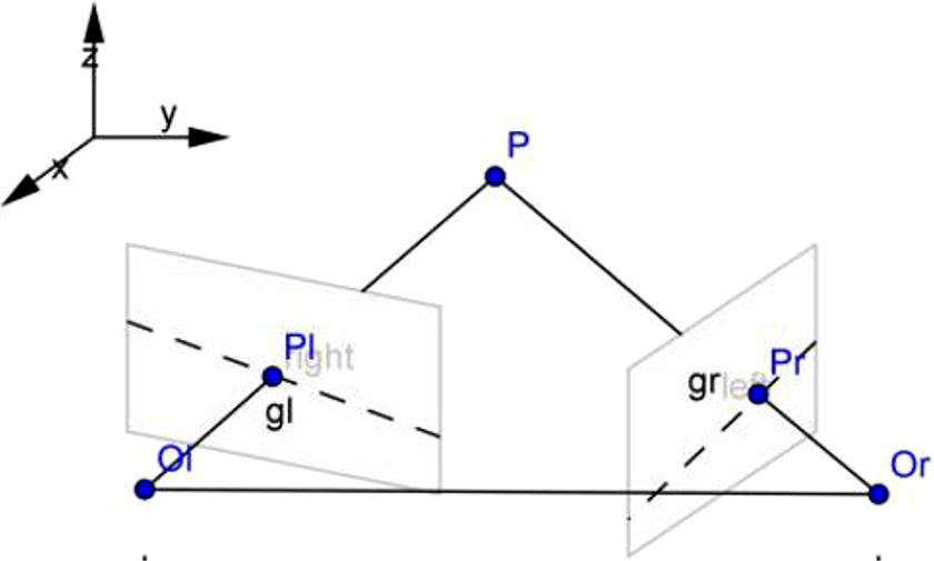
Relationship between space point and plane imaging.
For any point P on a space object, if camera C is used to shoot point P from coordinate origin O, the coordinate Pr of the point can be obtained from the pinhole model in the image plane coordinate system. Because in the image coordinate system, the position of the image point Pr not only represents the image point of space point P, but also represents all the image points on the line where OrPr is located. It is impossible to determine the 3D coordinates of a point by observing the object through a single camera position.
If two cameras are used to observe P-points on objects from different positions at the same time, according to the principle of imaging, P-points can obtain corresponding 2D coordinates on two cameras, and also at the intersection of OrPr and OlPl lines. In this way, two cameras can be used to determine the specific positions of points, lines and planes on any object in 3D space, so as to restore the structure of 3D space.
Stereo matching of images is to recognize the feature matching relationship of points in the same position on different imaging planes by algorithm. Through stereo matching of binocular images, the depth information of the target object is obtained, and then the 3D coordinates of the effective feature points in the target image are solved, which lays the foundation for the 3D reconstruction of the target object.
Experiments 3D reconstruction process and experiment
The left and right cameras built in this article are used to acquire the image of space object. After camera calibration, feature extraction and matching, the depth information of the object image is extracted by triangulation principle, and the 3D reconstruction of the object is carried out. The realization process is shown in Figure 6.

Flow chart of 3D reconstruction. 3D: three-dimensional.
By placing two circular objects in the white area of the calibration board, the left and right cameras of the binocular stereo vision system platform are used to collect images, and the images shown in Figures 7 and 8 are obtained. The images are processed in turn through the design process of the 3D reconstruction system, and the stereo matching results of the left and right images are obtained, as shown in Figures 9 and 10. By processing the stereo matching of the image, the 3D coordinates of the center point of the circular object in the space coordinates and the actual distance between the two points are obtained.

Image obtained from left camera for circular object.

Image obtained from right camera for circular object.

Matching results of circular feature points.

Matching results of circular feature points.
From the analysis of the experimental results, it can be seen that the distance between two points is 115.494 mm by analyzing the coordinate values of two circular objects in the image, as presented in Table 1. The 3D coordinates of one point (point 0000) are obtained as (−56.974133, −8.539707, 2150.015659). Therefore, the coordinates of any point in space and the distance between two points can be obtained by 3D reconstruction of 2D images, and the measurement accuracy and positioning accuracy are higher.
3D coordinates of objects in spatial coordinates.

3D: three-dimensional.
The gear is selected as the target object, and the gear image is analyzed using the platform. First, the collected images are preprocessed. Figures 11 and 12 are processed by smoothing filtering.

Initial cloud.

Smoothing filtering results.
The image of gear is acquired by the built camera, as shown in Figure 13. Then, the acquired image of gear is processed to obtain the background segmentation image of gear, as shown in Figure 14.
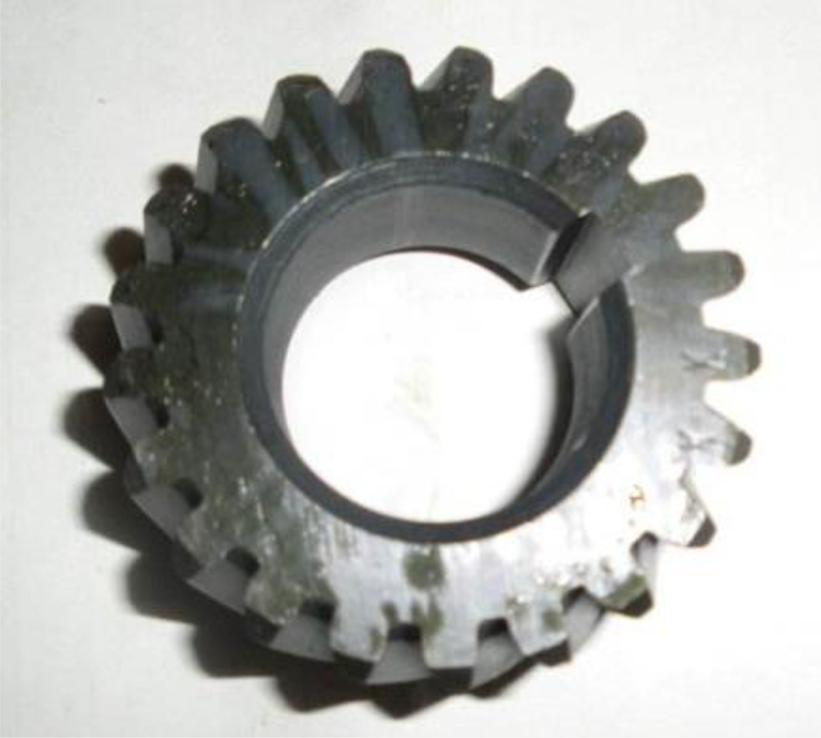
Image acquisition by camera.

Results of background segmentation.
Then the gear image is obtained through edge detection, feature matching and other processes. Finally, the depth information of the gear is obtained using the triangulation principle, and then the 3D effect of the gear is obtained, as shown in Figure 15. In the process of gear 3D reconstruction, each process is not independent, only to ensure that each process has good robustness, we can obtain high precision 3D graphics. Among them, the application of various algorithms or the improvement of existing algorithms plays a vital role in improving the accuracy of 3D reconstruction.

Generated 3D map. 3D: three-dimensional.
Through the above experimental steps using the built binocular stereo vision system platform to obtain the 2D gray image of the gear, through image processing analysis and optimization improvement of each process of the gray image of the gear, the mechanical part gear image can be restored to the 3D model of the target object. However, there are still some errors in the experimental results compared with the actual gear shape. The errors mainly include three reasons. First, in the camera calibration process, due to the errors in the manufacturing process of the camera’s own system. The obtained images were with tangential and radial distortion and the results of experimental calibration have certain error, also including a camera calibration algorithm that is not perfect. Second, in the feature matching process, the process is the key to the experimental results with high accuracy detection algorithm. Although the Harris algorithm and traditional Moravec algorithm by experiment have relatively higher matching accuracy, but because the number of feature points on the control is not very accurate, some feature points are removed, and the final results will affect the depth information extraction. Third, the influence of the external environment and the shortcomings of the hardware of the platform of binocular stereo vision system developed. Because of the limitation of illumination and hardware conditions in the acquisition of target images, there is a big error between the principle of images and the ideal image. It is difficult to ensure image preprocessing and camera calibration. Stereo matching has very high accuracy. These are also the areas for further optimization and improvement in this article.
Discussion
In this article, the classification of stereo matching algorithm is introduced in detail. 39 Moravec and Harris algorithms are compared and experimentally studied. According to the characteristics of Harris algorithm, the feature points in the target image are collected and matched. On the basic principle of 3D reconstruction, by analyzing the basic principle and method of 3D coordinate calculation, the coordinates of any point in space and the distance between two points are obtained, and the measurement accuracy and positioning accuracy are higher. In the system calibration, a two-step camera calibration method with simple steps and high calibration accuracy is used to calibrate the camera, and the camera’s non-linear distortion is obtained. Then, the projection matrix obtained by linear calibration is corrected, and a new projection matrix is obtained. Experiments show that this calibration algorithm does not require very high calibration requirements for instruments and equipment, and it is easy to operate. Even if some internal parameters of the instrument are unknown, the calibration results can be more accurate.
In the research of feature extraction algorithm, the mathematical principles of common detection algorithms such as edge detection operator and corner extraction operator are deeply studied and analyzed, and the original algorithm is improved. An interactive local corner extraction algorithm and a local edge extraction algorithm are proposed, which improves the performance and efficiency of the algorithm. Experimental results show that the feature extraction algorithm in this article can achieve better results.
In the research part of 3D point reconstruction algorithm, from the point of view of geometry, the 3D point reconstruction algorithm based on the common perpendicular segment of the non-planar straight line is deduced. In-depth experimental analysis of various 3D point reconstruction algorithms is carried out, and the reconstruction accuracy of several 3D point reconstruction algorithms is compared. The results show that the 3D point reconstruction based on the common vertical line segment algorithm of the nonplanar straight line in this article has high accuracy and small error. Finally, taking the gear of mechanical parts as the research object, the experiment of 3D reconstruction of gear based on 2D image is carried out on the platform of binocular stereo vision system, and satisfactory experimental results are obtained.
Conclusions
In this article, based on the research status of stereo vision at home and abroad and the basic theory of stereo vision, the calibration, image processing, stereo matching, and 3D reconstruction of several key technologies of 3D reconstruction technology based on 2D images are systematically and deeply studied. Because each stage of 3D reconstruction is not relatively independent, especially the accuracy of each step in the research has a great impact on the final results of 3D reconstruction. For this reason, in future research, the following three aspects should be further studied.
In the process of binocular vision reconstruction, the accuracy of camera calibration directly affects the result of reconstruction. To obtain higher accuracy, it is necessary to consider the influence factors of illumination and study the calibration method which can achieve sub-pixel accuracy. Stereo matching is the most important step in binocular vision reconstruction. How to improve the accuracy while ensuring the real-time requirement is the next step to consider.
Three different stereo matching algorithms are proposed in this article. An interactive stereo matching algorithm is proposed for stereo images with clear corner features. This algorithm is simple, practical, fast, and achieves high matching rate. In practice, it achieves good results for objects with corner features, edge features, and texture features. A feature point matching algorithm is proposed in this article. The algorithm combines affine transformation constraints, epipolar constraints, gray relativity constraints, uniqueness constraints, and mutual correspondence constraints. Experiments show that the algorithm is practical and effective, and the operation speed is fast. For stereo pairs with clear features, it can achieve a high matching rate for complex surfaces, and its characteristics are not obvious. This article presents a compact matching algorithm, which combines affine transformation constraints, epipolar constraints, gray correlation constraints, correlation constraints, uniqueness constraints, and mutual correspondence constraints. The algorithm is practical and fast. For complex stereo map pairs, the matching rate can be higher, and good results can be obtained in practical use. But in fact, there are many kinds of stereo matching algorithms that cannot be compared one by one, so finding better algorithms is our future work.
Footnotes
Declaration of conflicting interests
The author(s) declared no potential conflicts of interest with respect to the research, authorship, and/or publication of this article.
Funding
The author(s) disclosed receipt of the following financial support for the research, authorship, and/or publication of this article: This work was supported by the National Natural Science Foundation of China [Grant Nos 61741203 and 61866006]; Guangxi Natural Science Foundation [Grant No. 2016GXNSFAA380243]; Guangxi Higher Education Undergraduate Teaching Reform Project in 2019 [Grant No. 2019JGA222]; Guangxi Vocational Education Teaching Reform Research Project in 2019 [Grant No. GXGZJG2019A045]; Guangxi Innovation-Driven Development of Special Funds Project [Grant No. Gui Ke AA17204091]; Research Start Project of Guangxi Teachers Education University [Grant No. 0819-2017L10]; Guangxi Nanning Science and Technology Development Planning Project [Grant No. 20181015-5]. The authors gratefully acknowledge the support of the Logistics Engineering Innovation Laboratory of Nanning Normal University.