
Abstract
Light changes its direction of propagation before entering a camera enclosed in a waterproof housing owing to refraction, which means that perspective imaging models in the air cannot be directly used underwater. In this article, we propose an accurate binocular stereo measurement system in an underwater environment. First, based on the physical underwater imaging model without approximation and Tsai’s calibration method, the proposed system is calibrated to acquire the extrinsic parameters, as the internal parameters can be pre-calibrated in air. Then, based on the calibrated camera parameters, an image correction method is proposed to convert the underwater images to air images. Thus, the epipolar constraint can be used to search the matching point directly. The experimental results show that the proposed method in this article can effectively eliminate the effect of refraction in the binocular vision and the measurement accuracy can be compared with the measurement result in air.
Introduction
Exploring the ocean has been of perpetual interest since ancient times. In recent years, obtaining three-dimensional (3-D) geometric information has been an important application in underwater archaeological exploration, 1,2 marine biological research, 3,4 underwater equipment monitoring and maintenance, 5 and so on. The 3-D measurement techniques used underwater include photogrammetry, 6,7 3-D laser scanning, 8,9 structured light scanning based on grating, 10 –12 and underwater 3-D measurement based on images. 13
3-D measurement technology based on underwater laser scanning has certain advantages in large field, long-distance measurement, such as submarine topography measurement, but for the precise measurement of small and medium objects, underwater laser scanning-based measurement method still has the following problems: (1) it lacks of flexibility due to volume of the system; (2) the laser is required moving through a predetermined trajectory during measurement such that the operation is difficult; and (3) water and impurities cause serious scattering of the collimated laser beam, which affects the measuring accuracy of the system.
The method based on grating-structure light has advantages of high precision (the minimum and maximum deviations are −0.003 and 0.0012 mm for a flat plane 14 ), a large amount of data, and fast and automatic measurement. However, this method must project a specific grating structure that results in 3-D measurement of underwater equipment complex. First, a high illuminance digital light processing (DLP) projector and a definition camera should be mounted into a waterproof housing. Second, the optical grating of the DLP and the camera must be carefully calibrated. The high illuminance DLP projectors are more expensive. Generally, the DLP projector and the camera should have an included angle to focus the grating patterns, which makes the device more complicated.
With the development of computer vision, image-based 3-D system can accurately measure the operation condition of the underwater object and the geometric scale using images collected by high-definition (HD) cameras. It can effectively solve the shortages of the aforementioned underwater laser 3-D measurement systems. The accurate measurement system of underwater objects based on images obtained by HD camera can obtain the operating information and geometric information of the underwater object with strong flexibility, to solve the defects of the 3-D laser underwater measurement method.
Camera calibration is essential to achieve accurate and reliable measurements. Small errors in the perspective projection must be eliminated to prevent the introduction of effects in an underwater environment. As the light is absorbed in the water, affected by water pollution, and refracted at the interfaces of different media (water, glass, air), underwater camera calibration is complex. In this article, an image-based 3-D measurement in underwater conditions is presented. First, the underwater camera imaging system is analyzed, and then an accurate imaging model without approximation is utilized to correct underwater images into air. The image-calibration model is calibrated by the improved calibration algorithm, and the accuracy of the model is verified by 3-D measurement experiments.
The organization of the article is as follows. Section of ‘Related work’ summarizes other studies related to our work. Section of ‘Nonlinear underwater imaging model’ introduces the nonlinear underwater imaging model for self-containing. Section of ‘Accurate binocular stereo underwater measurement method’ explains the details of our approach. Underwater measurement experiments are described in section of ‘Experimental results’, before section ‘Conclusion’ presents the conclusion of our work.
Related work
Underwater camera calibration has been widely studied as the basis of underwater 3-D measurement. To take photos underwater, the camera is usually placed in a waterproof housing. The camera lens is not in direct contact with the waterproof shell. The light will go through different media before entering the imaging plane and refracting on the surface of two different media. Thus, the light is no longer a straight line; the perspective imaging model in the air cannot be directly used underwater. Queiroz-Neto et al. 15 and Sanchez-Ferreira et al. 16 reconstructed 3-D model without considering the influence of refraction, and the experimental results show that ignoring the influence of refraction produces a large deviation. Shortis et al. 17 present a review of the methods used for the detection, identification, measurement, tacking, and counting of fist in underwater stereo-video image sequences. Their shortcomings and characteristics were identified and compared. It provides a comprehensive overview of video-based stereovision methods.
Aiming at solving the influence of refraction, many studies propose various methods to approximate the underwater imaging process. The first category entails using the physical assumption to transfer the center of the camera lens to the plane of refraction by a special optical components. 18 –23 Then, the special shape of optical component offsets the refraction of light. However, these methods are not easy to implement because of the limitation of optical component progress and the strict requirement of manufacturing.
The second class entails calibrating the underwater camera with an auxiliary plane. 24,25 These methods can determine the direction of the incident vector by adding an auxiliary calibration board and then calibrating the camera parameters using this known quantity. The third type regards refraction as a change in the focal length. 26,27 The extension line of the incident light will intersect the optical axis of the camera eventually. Because the change in focal length is associated with the incident angles of image points, the method will result in some errors. The incident angle of light is larger, which cause larger errors.
Another category is to approximate the error caused by refraction underwater as lens distortion. 28 –30 The pixel offset error is regarded as refraction error caused by the distortion of the lens itself in this method. Through the calibration of the camera parameters and image distortion correction, the method can eliminate the influence caused by refraction. However, because the influences of different pixels by refraction are different, this method cannot correct the whole image with uniform distortion parameters particularly in the boundary areas of high-resolution image or in the case of foreshortening for a large object, and this will result in an obvious error.
The fifth kind of method entails the underwater imaging process with physical model and developing the corresponding calibration algorithm according to the imaging model. The hypothesis proposed by Treibitz et al. 31 is that the imaging plane is parallel to the refraction plane. The underwater imaging process of single refraction is analyzed, and the calibration algorithm is improved to calibrate the parameters of the underwater camera. Jordt-Sedlazeck and Koch 32 proposed a camera-calibration method based on the shell. The method calibrates the refractive plane of the normal vector and distance from the camera center with the optimization method. However, the method requires a suitable initial value. Agrawal et al. 33 build a multiple-refraction imaging model. The method uses the five-point algorithm to calculate parameters, including the refractive index, refracted plane’s normal vector, and distance between the refraction plane and the camera center. However, the model is complex, which makes the calculation extensive. Chen and Yang present a calibration method of binocular vision based on an underwater camera. 34 The method optimizes the camera parameter through 3-D point remapping with the constraint of two incident lights lying on the same plane. Yau et al. proposed a method for an underwater camera-calibration method based on different light refractive index. 35 The method mainly uses the principle that different frequencies of light in water have different refractive indices to design a calibration board that can emit two different frequencies of light.
In recent years, many scholars have extensively researched underwater 3-D measurement. Some early underwater reconstruction work neglects the influence of refraction. The multi-view method was used by Kang et al. 36 in 3-D reconstruction and measurement underwater. The method discusses the effect of ignoring refraction during 3-D reconstruction and measurement. Chari and Sturm 37 analyzed the refraction phenomena in detail to prove the existence of the fundamental refractive matrix in underwater binocular vision. However, they only provide the simulation results, but no actual experimental data. Chang and Chen proposed an underwater 3-D reconstruction method. 38 In this method, all cameras share a refractive plane. Refraction influence is modeled as a depth energy model. This method requires a known refraction plane and an additional inertial measurement unit to measure the camera rotation angle. Sedlazeck and Koch 39 provide a more flexible approach and their method does not need calibration; however, the method is time-consuming and the result is not satisfactory. Yau 40 uses the multi-vision method to reconstruct underwater objects, according to the principle of underwater imaging; this method improves the traditional Bundler algorithm and patch-based multi-view stereo algorithm to reconstruct underwater objects. Although it can achieve a good result, the cost is high. Pedersen et al. 41 address the underwater calibration camera based on ray tracing using Snell’s law, while other two methods, an approach relying solely on in-air camera calibration and an approach with the camera calibration performed under water, are compared.
In this article, a Digital Single Lens Reflex (DLSR)-based stereo underwater vision system is presented to verify the effectiveness of the algorithm as the DLSR camera is easy to operate and has high image quality with affordable price, which is important for underwater stereo system. Our system can used in high accurate measurement environment. The contributions of this article can be summarized as: According to the nonlinear underwater refraction imaging model, the traditional Tsai’s calibration algorithm and the planar checkerboard calibration algorithm are improved to obtain more accurate parameters such as the camera internal parameters and external parameters, as well as the distance between the camera center and the refractive plane. An underwater image correction method based on camera calibration parameters is established. The underwater image is restored to the image in the air through image correction. The corrected image is used to carry out 3-D measurement of the size of underwater objects.
Nonlinear underwater imaging model
In air, perspective imaging model is expressed as the correspondence between the spatial 3-D point and its imaging point, illustrated in equation (1)
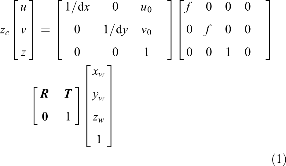
where
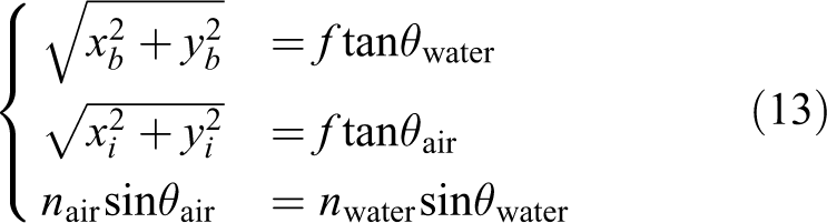
Light reflected from an object arrives at waterproof housing of camera and then strikes surface between the housing and the air. Different refractive indexes of air and glass cause refraction. Finally, light enters the camera and forms an image. All the light entering the camera goes through this process. According to Snell’s law, we get the following equation
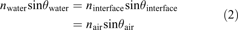
where
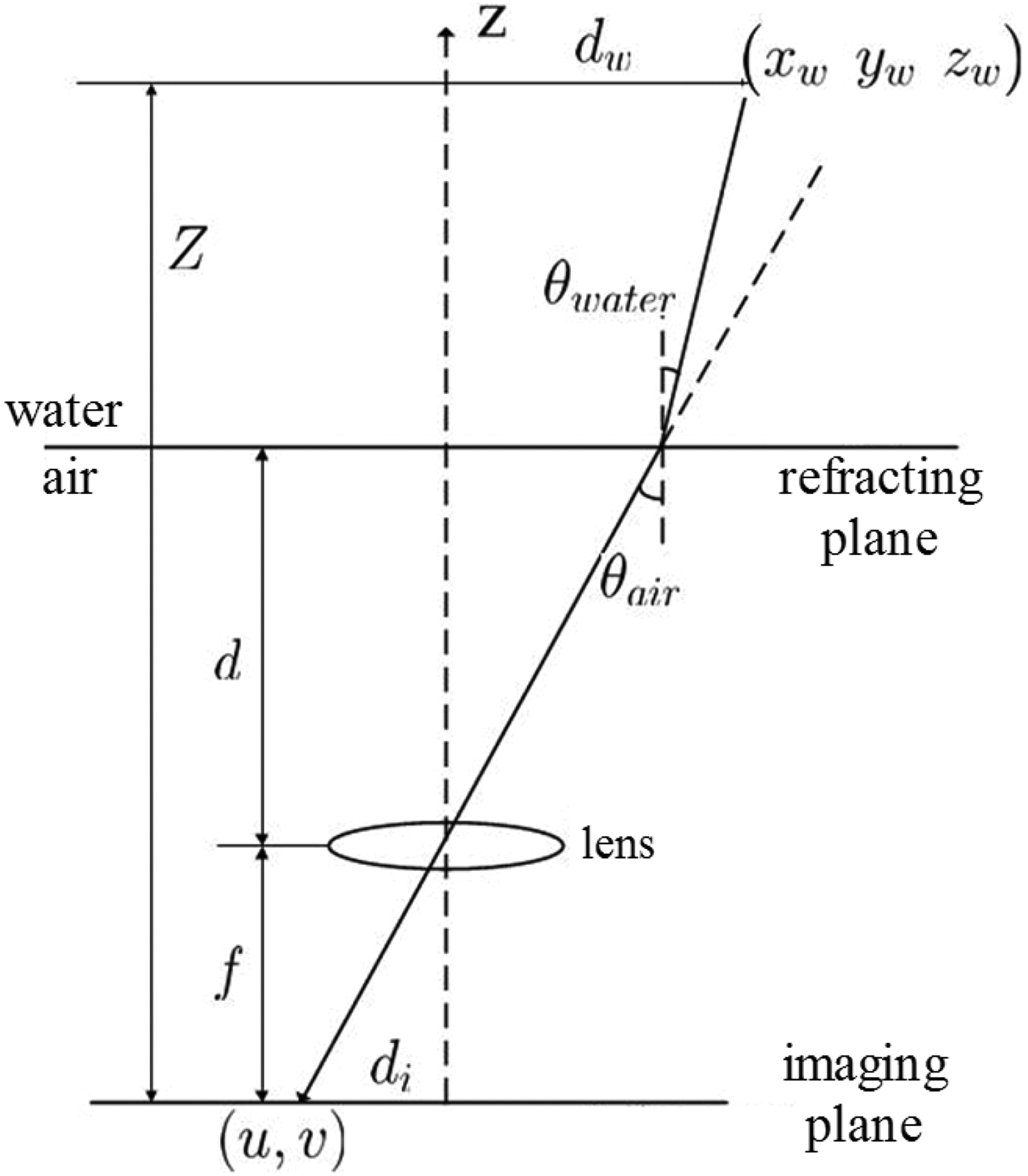
Underwater imaging model.
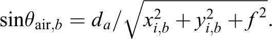
Assuming waterproof housing surface is parallel to the camera imaging plane; f is the camera focal length, and d represents the distance between the refracting plane and the camera center, as shown in Figure 1;

where
Accurate binocular stereo underwater measurement method
System calibration based on Tsai’s method
As Tsai’s method only uses one image to calibrate the camera,
42
it is suitable to be employed in underwater for convenient image acquisition. The internal camera parameters are the intrinsic property of a camera. Thus, we can calibrate the intrinsic parameters,
where

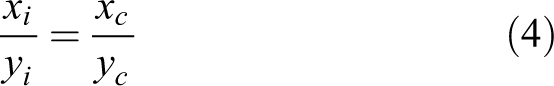
From equations (4) and (5), we can compute the rotation matrix

The incident ray is coplanar with the optical axis of the camera before and after refraction, so the radial uniform constraint is still valid in underwater imaging and can be used to obtain camera parameters. After we obtain the intrinsic matrix
System calibration based on planar pattern
As the Tsai’s method needs a 3-D calibration pattern, it is not easy to guarantee the orthogonality of two planes. In this article, we utilize a two-step method to calibrate the underwater camera by using on planar calibration pattern based on Zhang’s method.
43
First, the planar calibration pattern and the binocular stereo system are placed in the water tank without water. Twenty images of the calibration pattern are captured in different orientations. The position of the calibration board is fixed after the last calibration pattern photo is taken. The intrinsic and extrinsic parameters (
Underwater binocular vision measurement method in 2-D and 3-D
2-D Underwater measurement with one camera
According to the underwater imaging model, a straight object is imaged to appear bent in the raw image; however, the object should be undistorted in air, as shown in Figure 2. The two-dimensional (2-D) underwater measurement is to estimate the length D from the blue curve. After we acquire the parameters of the underwater camera, 2-D measurement in water can be carried out according to equation (7), 31 where the object should be positioned frontoparallel to the interface and camera

where


The straight object imaged in water (blue curve) and in air (straight line).
Epipolar constraint and 3-D underwater measurement
Epipolar geometry plays an important role in stereo matching in binocular stereovision measurement. In the binocular stereo, two cameras capture a point in physical space from different angles, and two image points are respectively formed in these two images. To obtain the object depth information, the corresponding k-point pairs in two images should be found. Finding the corresponding point in the whole image is very time-consuming; thus, we need some constraints to reduce the search range.
As is shown in Figure 3,

Epipolar geometry.
Suppose that the projection matrixes of two cameras are

The epipolar line equation can be expressed as follows

Here,
Underwater epipolar constraint
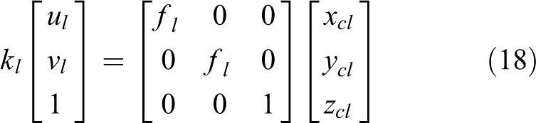
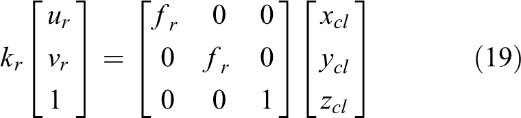
Based on the underwater imaging model, we can build the underwater epipolar equation. The underwater imaging model is shown in equation (3). The corresponding projection matrices of the two cameras are

However, unlike model in air, the underwater imaging model is no longer the perspective imaging model. Given the intrinsic parameters matrices of two cameras

From equation (10), we can find that the epipolar constraint is related to the parameters of the vision system (camera intrinsic parameters and the two camera structural parameters). If the camera is placed in air, because the model is a linear model, the epipolar line is a straight line. The parameters of the camera in the underwater environment are not only related to the internal parameters of the camera but also to the parameters of the underwater imaging system, for example

In equation (11), the intrinsic parameter matrices are no longer linear matrices and the epipolar line is a curve. Therefore, in underwater epipolar alignment, we need to find out the corresponding curve equation in another image, and then find the matching point on the curve. Because of the complexities of obtaining the curve equation in underwater environment, it is difficult to matching images. Thus, in this article, we propose an image rectification method to correct the images before the epipolar line registration.
Underwater image correction
The underwater imaging is no longer a perspective imaging model because of refraction, which leads to the epipolar line is no longer a straight line. According to the calibrated underwater camera parameters, we correct the images and map the underwater images into the air images. Then binocular correction and the subsequent 3-D measurement can be carried out on the image pairs.
As shown in Figure 4, assuming that AB is an incident light into water; all points on this line are mapped to the same pixel


Approximation model of underwater imaging and air imaging.
Thus, we find out the relationship between
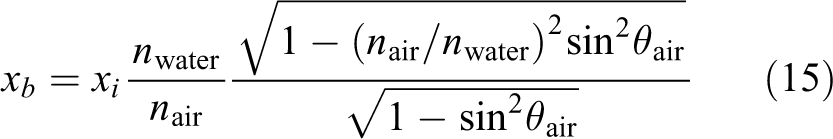
According to the mirror image consistency constraint, points

Through equation (14), we can derive equation (15)
Thus, the coordination of imaging point in air environment is expressed as equation (16)
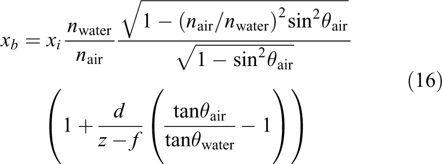
Then, we convert to image coordinates by using equation (17)
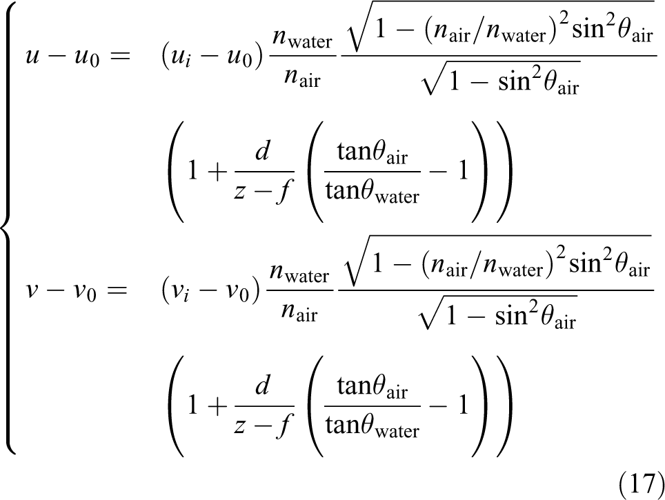
In fact,
According to equation (17), we can convert the underwater images in the air. The coordinates of a pixel on the underwater image are noninteger after the coordinate is transformed through equation (17). Thus, we need to interpolate the pixel after transformation. As the coordinate transformation formula established in this article is not reversible, we cannot obtain the coordinates of pixels on the projected image through converting the coordinates of pixels on the target image. We apply forward mapping-based bilinear interpolation method in this article.
Underwater binocular stereo 3-D measurement
After the underwater images are corrected and restored in air, we can perform binocular correction and make the left and right images aligned, and then do stereo matching. Binocular stereovision measurement is based on the disparity map after image feature points matching. Figure 5 shows the schematic of binocular stereovision measurement.

The binocular stereo measurement.
3-D coordinates of the object is
Suppose the relationship between the left and right camera coordinate systems is
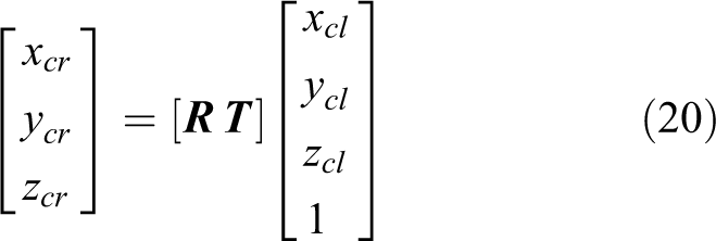
According to equations (14) to (16), the real 3-D coordinates of the object can be calculated as equation (21)

where
Experimental results
The experimental equipment used in this study is an underwater binocular stereo system, including two Canon 70D cameras enclosed in a metal box with a glass window in the front (the thickness is 10 mm), Canon EF 50 mm f/1.4 lens, a glass sink filled with water, camera wireless controller, and so on, as shown in Figure 6. The two cameras are mounted on two slide rails, along which the positions of the cameras can be adjusted. As the cameras are fixed on the slide rails, the system is calibrated only once, unless the position of the cameras is changed. Then two remote controllers, CamFi II, are mounted on the cameras to connect with the wireless monitor. The camera shooting parameters can be set and the picture can be viewed on the remote monitor. There are four experimental subjects: two checkerboards (a plane pattern and a right-angle target), a stone sculpture, Easter avatar, and pirate avatar.
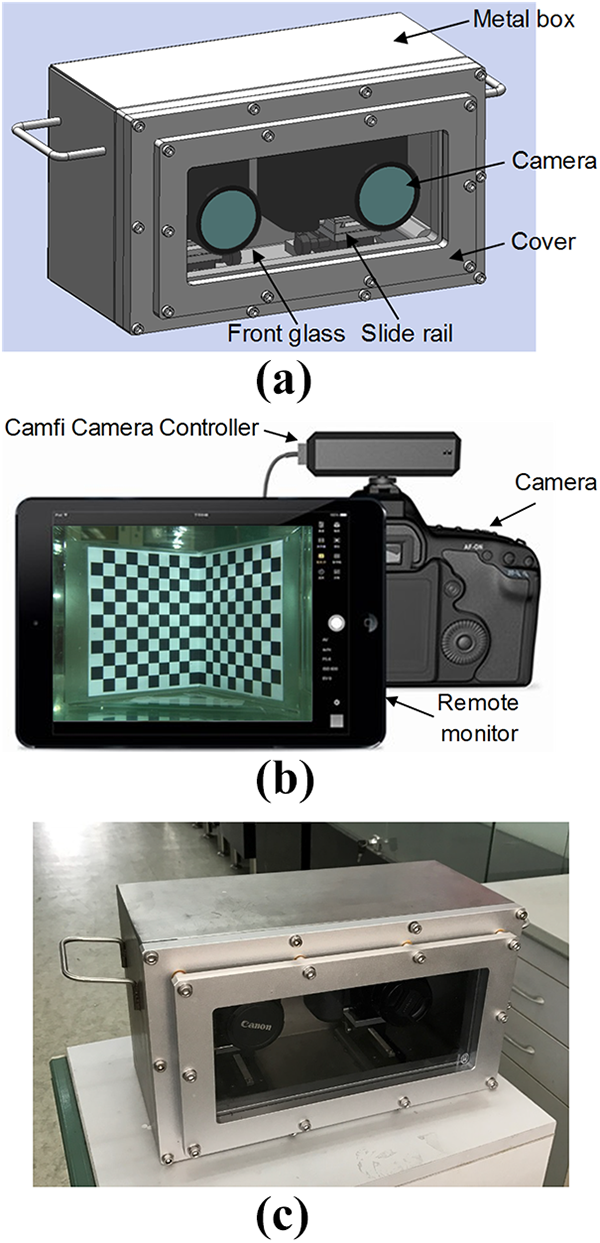
Underwater measurement of experimental equipment. (a) 3-D CAD model of the waterproof housing. (b) Underwater stereo system. (c) Scheme of wireless controller. 3-D: three-dimensional.
First, the intrinsic parameters of camera can be calibrated in air by Zhang’s method.
43
Figure 7 is a highly accurate checkerboard with 400 mm × 300 mm dimensions and 12 × 9 grids, and each grid size is 30 mm × 30 mm with accuracy ±0.2 mm. It is a commercialized product to guarantee the accuracy. Sixteen images in different orientations are utilized to calibrate the intrinsic parameters of the camera. The acquired internal camera matrix is

A planer checkerboard in water.
After we acquire the intrinsic parameters of the camera, the stereo underwater system can be calibrated. The calibration target was placed into the water tank to acquire one image, as shown in Figure 8. The checkerboard size is

A camera equipped with a remote controller and monitor.
The first experiment is to verify the measuring accuracy on a 2-D plane. The checkerboard is positioned parallel to the image plane, as shown in Figure 7. The experiment was divided into four groups, one in the air environment and another is in underwater. By utilizing the calibrated parameters, we can compute the coordinates of the checkerboard corners. After we compute the size of each grid, the accuracy can be evaluated using

Comparison of measurement error in 2-D of a checkerboard in air and in water. (a) Measurement errors in air. (b) Measurement errors in water (
Then we experiment underwater binocular images registration to align the left and right images. Figure 10 shows the binocular alignment results without underwater image correction. We find that the same features cannot be found on an epipolar line. Two small portions in top and bottom results are zoomed in, from which the corresponding features greatly deviate from the epipolar line. The distances from the features (yellow points) to the epipolar lines vary. Next, the underwater image pairs are corrected and aligned by using the proposed method (see Figure 11). Comparing to the results in Figure 10, the stereo images are well aligned, as seen in the zoomed-out portions in the top and bottom images. We can find that the features located on the epipolar line, which will facilitate the feature matching.
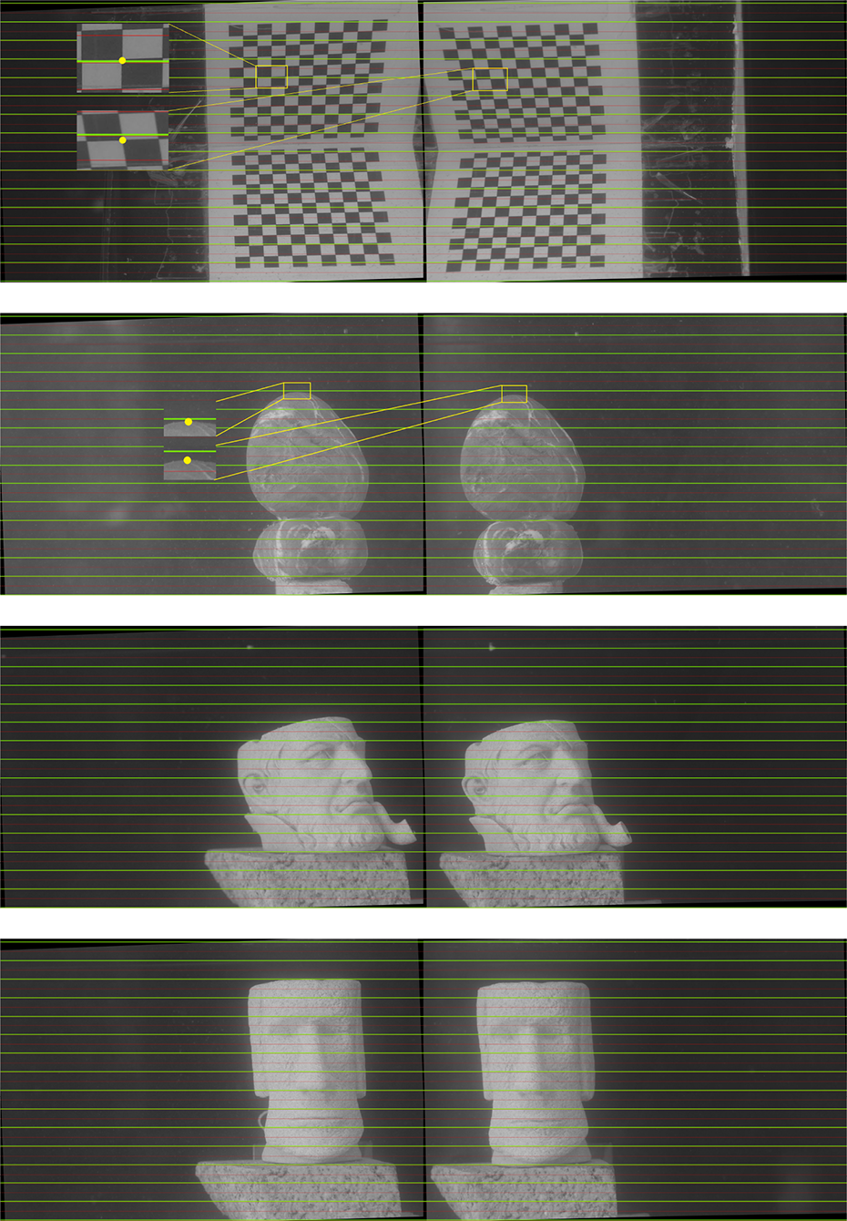
Binocular correction results before rectification.
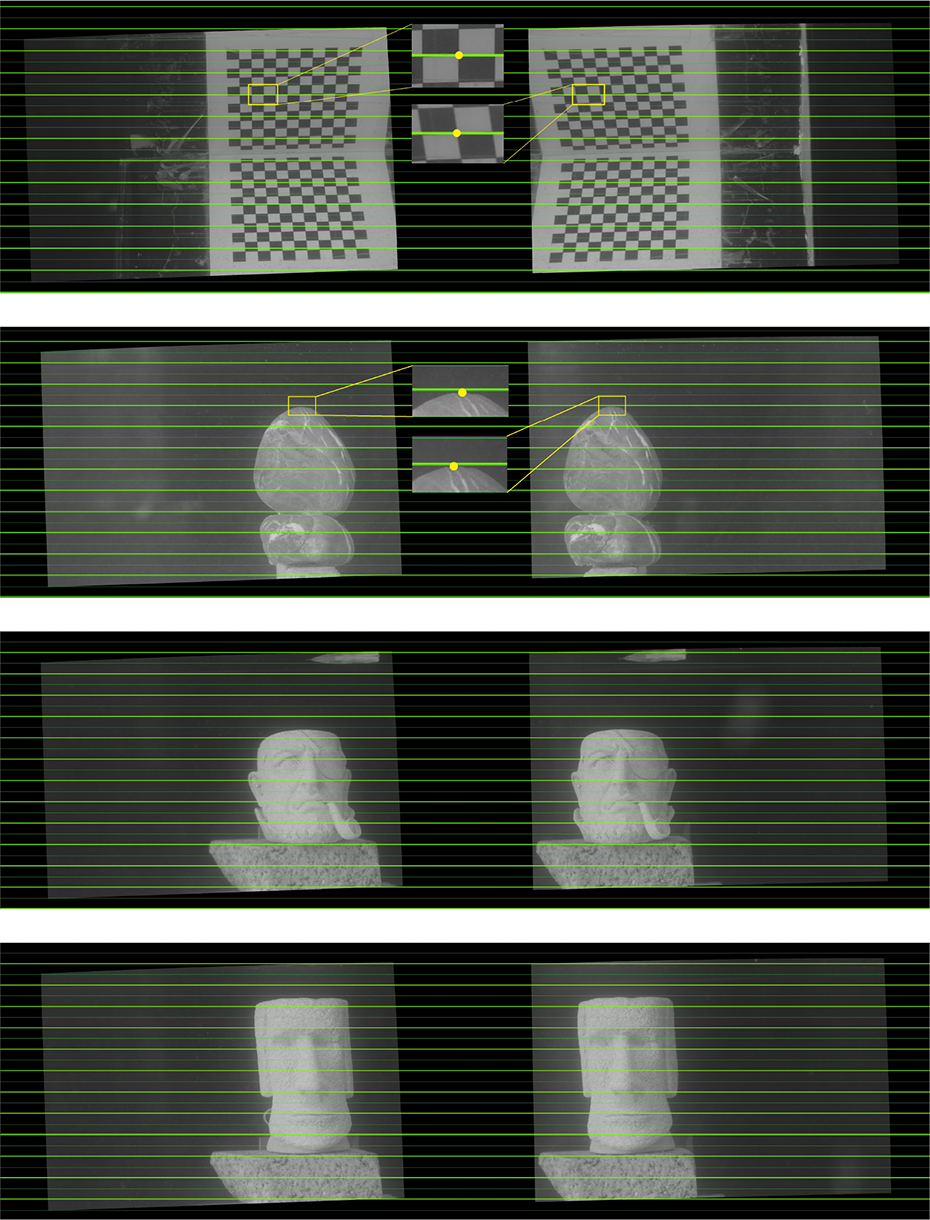
Binocular correction results after rectification.
To further verify the measurement accuracy in three dimensions, we utilize the calibration target to measure the accuracy as it has accurate ground-truth size. The measurement part is the lower half of the stereoscopic calibration plate, as shown in Figure 12. We divide measurement experiments into two groups. First, we use the coordinates of the corner point in left and right images and the external parameters of the binocular vision system to calculate the 3-D coordinates of the corner directly without matching in the air. Figure 13 is the experimental result, in which Figure 13(a) and (b) shows the different views of the computed 3-D coordinates of the corners. We can fit the plane with the computed 3-D coordinates of the corners and measure the distance of each 3-D point from the fitted plane. Figure 13(c) shows the measurement results and Figure 13(d) shows the distance error between each corner point. Measurement error is within 0.14 mm, and the mean error and standard deviation are 0.01 mm and 0.004, respectively. Second, the corrected underwater image pair is used for binocular stereo matching to obtain the 3-D coordinates of the matched corner points, as shown in Figure 14. Figure 14(a) and (b) shows different views of the 3-D points. The distance error to the fitted plane is illustrated in Figure 14(c) and the corner distance error is shown in Figure 14(d). The mean and standard error of the corner distance are 0.071 mm and 0.101, respectively. Then, we compare the underwater reconstruction result with a ray tracing-based method 41 in Table 1. Star (*) denotes in-air calibration, underwater calibration, and ray tracing approach. 41 In-air calibration showed to be the most inaccurate as it does not take refraction into account. It is clear from Table 1 that the proposed algorithm has high accuracy compared to the underwater calibration result of ray tracing approach. 41

The 3-D measurement subject. 3-D: three-dimensional.

Reconstructed 3-D points in air and distance errors from the points to fitted plane and grid’s length differences. (a) Reconstructed 3-D corners. (b) The fitted calibration plate plane. (c) Distance errors of corner to the fitted plane. (d) Distance errors between corner points. 3-D: three-dimensional.

Reconstructed 3-D points in water and the grid’s distance errors. (a) Reconstructed underwater 3-D corners. (b) The fitted underwater calibration plane. (c) The side view of the reconstructed corners. (d) Distance from the reconstructed corners to the fitted plane. 3-D: three-dimensional.
Comparison of the underwater 3-D reconstruction errors with the ray tracing method. 41

3-D: three-dimensional.
Conclusion
In this article, an underwater image-correction algorithm is proposed based on the underwater images nonlinear model. The method is used to reconstruct the underwater image captured by the binocular vision system according to the calibration parameters of the underwater camera. From the experimental results, it can be seen that the image can be well aligned after binocular correction using the corrected image. Then, the 3-D coordinates of the feature points in the underwater calibration plate are obtained by using the corrected underwater images. Underwater 3-D measurement is carried out using the corrected underwater image. The 3-D coordinates of the feature points can be used to fit the plane of the calibration plate. The accuracy of the method is verified by the distance of the 3-D coordinate of the feature point from the fitting plane and the result is performed well. In future study, the presented calibration approach would be utilized in dense stereo match and 3-D reconstruction in underwater environment.
Footnotes
Declaration of conflicting interests
The author(s) declared no potential conflicts of interest with respect to the research, authorship, and/or publication of this article.
Funding
The author(s) received no financial support for the research, authorship, and/or publication of this article.