
Abstract
The ability to resist the effect of wind disturbance is vital for micro air vehicles. As the most compact rotor configuration for micro air vehicles, coaxial rotors will be the preferred choice for this type of devices. In this paper, the aerodynamic performance of the coaxial rotors considering the wind gust is presented with both experiments and simulations. First, effect of wind disturbances on the micro air vehicles flight was introduced. Then, low-speed wind tunnel tests were performed on a coaxial rotor with a spacing 0.39 R to obtain the performance in both horizontal and vertical wind of 0–5 m/s with the revolutions per minute ranging from 1500 to 2400. Finally, computational fluid dynamics simulations, as a means of visualizing the flow field to compensate the intuition of the experimental data, were applied by using the sliding mesh to capture the detailed interference of flow field with the distributions of streamline and velocity vector. Compared with wind tunnel tests, simulation results were highly consistent with experiments that allow to capture the flow details around the rotor tip effectively. In addition, the aerodynamic performance was deteriorated by vortices moving or deforming around the blade tip. Also, coaxial rotors can effectively resist the wind disturbance in the horizontal direction while the rotor performance was found to be declined in the vertical wind.
Introduction
Micro air vehicles (MAVs) are designed to be able to cruise close to a building or even move through a narrow window or door while being very small. Therefore, it is necessary to conduct investigations to figure out the wind effect on MAVs when they are flying close to obstacles at low speed. At this time, a horizontal wind or a vertical wind may be included in these conditions. Coaxial rotors, as a compact rotor unit of MAVs, provide the required lift and power to hover and forward flight for MAVs. Their aerodynamic characteristics will affect the overall aerodynamic performance and hover efficiency of MAVs.1–3 Moreover, the axial separation between the upper rotor and the lower rotor produces stronger aerodynamic interference. 4 The complicated vortices and helical wake are generated at high rotational speed which may affect the aerodynamic performance, additionally when the wind disturbance is introduced. The formed vortices may shed from the blade tip, and eventually enhance the mutual interference at the blade while moving downward. Furthermore, because part of the lower rotor is in the wake of the upper rotor, the whole flow distribution and boundary layer become much more complicated. Especially when the wind effect is introduced, wind disturbance interfered with the own wake of the each rotor and resulted in the complicated flow field and aerodynamic fluctuation. Eventually, it might also affect the maneuverability and stability of the vehicle. Accordingly, aerodynamic performance of coaxial rotors in a natural environment is also affected by the flow in different directions. 5 Therefore, it is important to conduct theoretical and experimental study to figure out the ability to resist the wind gust for coaxial rotors in a natural environment.
By viewing recent researches concerning the coaxial rotors, it is found that there is a very large body of knowledge of computational analysis or experimental tests which documents the flow field of the coaxial rotors. For instance, Lakshminarayan and Baeder 6 used the computational fluid dynamics (CFD) simulation to calculate the hovering performance and aerodynamic characteristics of coaxial rotors. Lei et al. 7 and Prior 8 reviewed the performance of the coaxial rotors both by experiments and simulations at low Re environment. Xu et al. 9 and Ruzicka and Strawn 10 adopted the moving grid to analyze the aerodynamic disturbances in coaxial rotors. For the experimental studies, Silvestre et al. 11 and Ramasamy 12 earlier carried out a blowing test in a wind tunnel to study the aerodynamic characteristics of H-34 rotors. Furthermore, Quackenbush et al. 13 have carried out the blowing tests on the articulated single rotor in the Martin wind tunnel of Maryland University. In addition, Moble et al. 14 have conducted wind tunnel tests on the coaxial rotors in hover and different forward ratio. Ma et al. 15 studied the rotor characteristics of flow field in the water tunnel by using particle image velocimetry (PIV) technology to obtain the distribution of vortices and velocity vector. These researches published many technical papers and shared a vast amount of knowledge to study the aerodynamic characteristics of coaxial rotors. However, the effect of wind in different directions on coaxial rotors is not included, and these results are focused on either the CFD simulation or the experiments only. Also, the majority of the data are not applied as the aerodynamic inputs for MAVs flight. Thus, current data are deficient to satisfy the flight control for MAVs.
In this paper, theoretical simulation considering the wind gust in different directions is presented with the wind distribution for typical MAVs, and wind tunnel is also applied to examine the thrust and power of coaxial rotors in hover. Finally, aerodynamic interference with the flow field and the ability to resist wind gust for the optimal coaxial rotors are analyzed in detail by measuring the thrust and power changes. To this end, this work seeks to answer the following questions: (1) For coaxial rotors during hovering, how does a change in wind speed or wind direction affect maximum thrust or power consumption as a whole? (2) How does the propulsive efficiency suffer or improve in all these cases? and (3) How is the flow field affected by a change in wind speed or wind direction?
Theoretical models
Effect of mean wind speed
A MAV will, for the overwhelming majority of flights, be subjected to a mean wind speed greater than zero. Wind speed up to 5 m/s occur most of the time for a typical MAV at a height of 20 m. 16 Also, it will need to be reacted by increased power, increased angle of attack, sideslip and so on in a quasi-steady manner to maintain the desired flight path when the wind speed is higher than 5 m/s (strong or relatively rare wind). Furthermore, the horizontal and vertical components of wind are more significant in contributing to roll disturbances. 17 These are a result of a lift difference across the span of the MAV where the horizontal component primarily increases (or decreases) the velocity vector, which in turn alters the lift production, and the vertical component affects the angle of attack. Above all, the typical wind environment considering both horizontal and vertical wind for a MAV flight is showed in Figure 1.
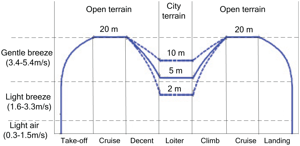
Mean wind speed variation for a typical MAV flight.
Above all, wind effect is only involved from the light air to the gentle breeze with the speed limited to 5 m/s, and both the horizontal and vertical winds are considered.
In this paper, the coaxial rotors are part of an Octorotor MAV. Based on the preliminary study in Lei et al., 18 the effect of incoming flow on the coaxial dual rotor flow field is shown in Figure 2 which is also verified by the simulation results in this paper (where the black line is the trace without the incoming flow and the blue line is the trace under the influence of the incoming flow).
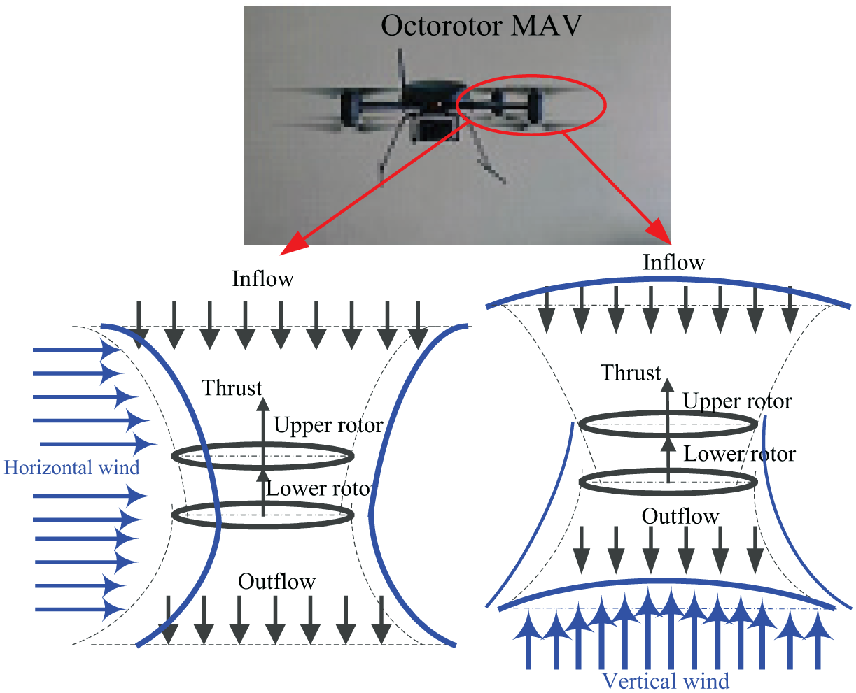
Flow direction of wind disturbance on the flow field of the coaxial rotors.
As showed in Figure 2, it is clear that the wake of the coaxial rotors moved with the horizontal flow. However, this effect may be not that significant due to the mutual coupling of the flow fields between the upper and lower rotor. Moreover, the horizontal flow will also increase the inflow between the rotors which may result in the overall increase in lift. In addition, when the vertical flow acts on the entire rotor, the entire flow field will change due to the interference between incoming flow and coaxial interactions, which may cause severe turbulence and greatly affect the thrust and even vibration.
Wind tunnel tests
Basic parameters
The rotor manufacturing is commissioned by the Beijing Satellite Factory custom with carbon fiber and the special manufacturing process. The rotor profile is presented in Figure 3.

Rotor profile: (a) side view and (b) front view.
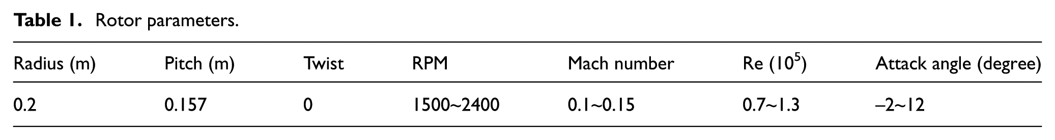
The rotor parameters are presented in Table 1, and the chord length variation is shown in Figure 4 (where r is the dimensional radial coordinate, 0 < r < R).
Rotor parameters.
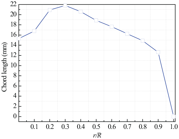
Chord length distribution.
Experimental setup
The upper rotor rotates counterclockwise, and the bottom rotor rotates clockwise. The axial separation distance between the top and lower rotors is 0.39 R, at which the aerodynamic performance for the coaxial rotor was proved to be the best in the range of 0.32 R∼0.75 R. 18
In this paper, the wind tunnel will generate the horizontal and vertical airflow to simulate the wind around the rotor. Since the wind in the natural environment is usually less than 5 m/s, the low-speed wind tunnel (Ma < 0.4) is selected to produce the wind with different speeds. According to the common wind speed in natural environment, light breeze (1.6∼3.3 m/s) and gentle breeze (3.4∼5.4 m/s) are chosen to conduct the blowing test with horizontal wind and vertical wind, as compared to the thrust and power of coaxial rotors without the wind effect. In this way, the effect of wind disturbances on the aerodynamic performance of coaxial rotors in natural environment is studied.
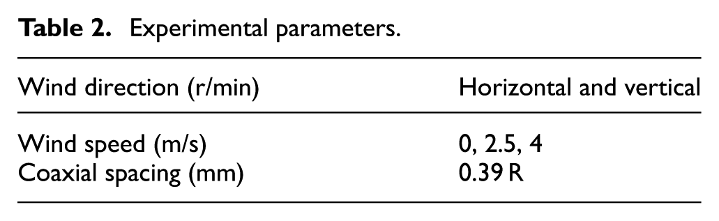
The low-speed wind tunnel can be divided into four parts, including the contraction section, the test section, the expansion section and the power source. Coaxial rotors are located in the middle of the test section, in which the airflow is required to remain stable with the turbulence intensity of 7%, and the section size is 1 × 1.5 m. In the experiments, the rotational speed, thrust and power are recorded in the computer. Speed of the horizontal and vertical wind is determined as 0, 2.5 and 4 m/s, respectively.
Experimental setup is shown in Figure 5, and experimental parameters are presented in Table 2.
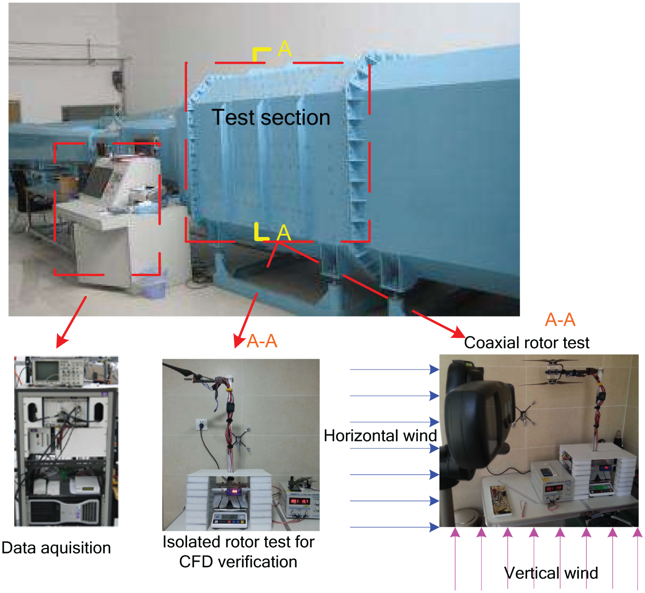
Wind tunnel test.
Experimental parameters.
The rotational speed of the brushless DC (BLDC) motor was controlled through pulse width modulation (PWM) from a remote controller and the resultant speed was measured by using a handheld tachometer (model: DT-2234C, accuracy: ±(0.05% + 1 d), Wenzhou Shengce Instrument Co. Ltd., China). The thrust sensor (model: CZL 605, accuracy: 0.02% FS, Tianjin JinLiang Equipment Co. Ltd., China) was mounted on the rotor shaft to measure the rotor thrust. Similarly, a torque sensor (model: HLT-131, accuracy: 0.5% FS, Hualiteng Technology, China) was fixed on the motor to obtain the rotor torque which is measured by the technique of resistance strain gauge.
Error analysis
The main errors introduced in the experiments are (1) the deviations of the rotational speed; (2) the accuracy of the thrust sensor and torque sensor which is presented the last section; (3) uncertainty of key parameters to characterize the aerodynamic performance of coaxial rotors, including thrust coefficient CT, power coefficient CP and Figure of Merit (FM); and (4) variation of the wind speed in the lower speed wind tunnel which is below 0.15 m/s.
Error in the rotational speed depends on the finite number of magnets which excite the Hall Effect sensor in the motor. For the selected motor, there are 24 magnets which result in an uncertainty of 1/24 revolution for each rotor rotation. Therefore, there is an error of 1/24 × 60 = 2.5 r/min by the number of times for a magnet passing over the Hall Effect sensor in 1 s.
The aerodynamic performance of the rotor which is characterized by CT, CP and FM are defined as follows
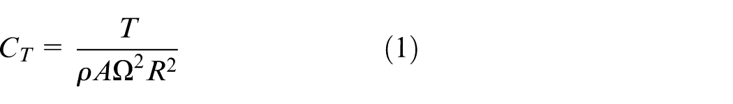
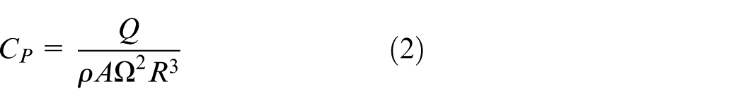
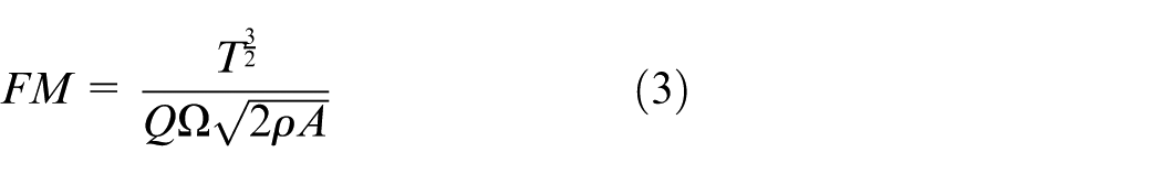
where Ω is the angular velocity, R is the blade radius, ρ is the density of air and A is the area of the rotor disk. Figure 6 showed the mentioned aerodynamic parameters of the rotor.
Aerodynamic parameters of the rotor.
To calculate the uncertainties in CT, CP and FM, we applied the “Kline–McClintock equation” presented in the following equations 19
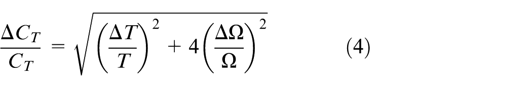
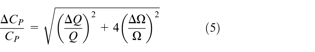
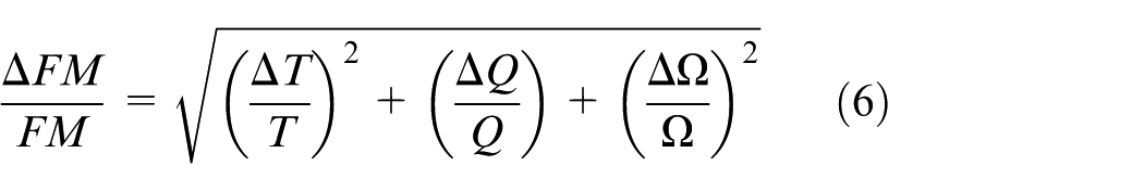
At last, the uncertainties in CT, CP and FM are determined as 1.2%, 1.1% and 1.5%, respectively.
The values of uncertainty that are presented in this study are all calculated for 95% confidence levels.
Experimental results
Results of the wind tunnel tests for coaxial rotors are shown in Figures 7 and 8, which is more accurate than the values presented in Lei et al. 18 The wind tunnel tests of 0 m/s are consistent in the horizontal and vertical wind for the quantitative comparison.
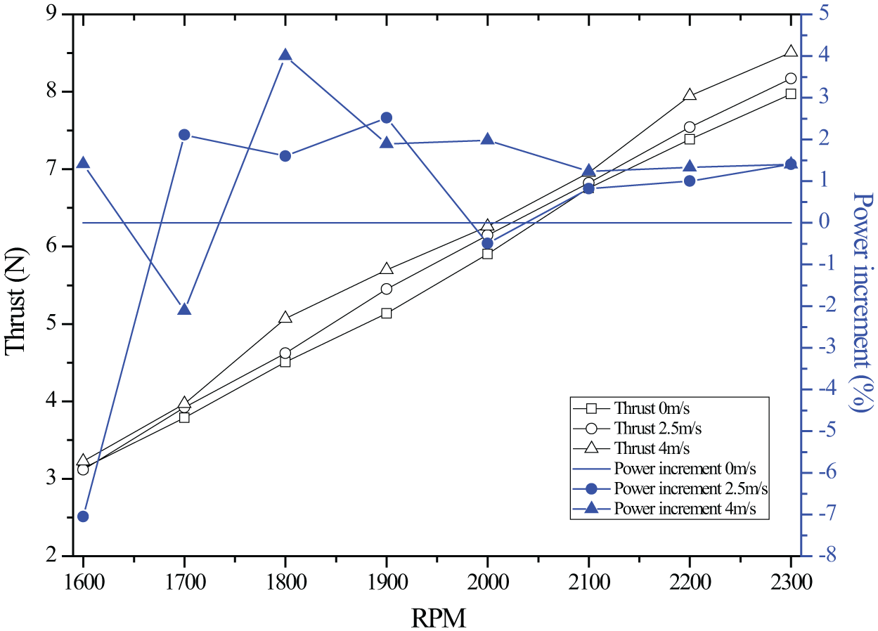
Thrust and power variation in the horizontal wind.
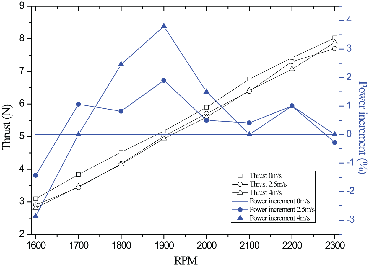
Thrust and power variation in the vertical wind.
As shown in Figure 7, the rotor thrust increases with the wind speed in horizontal wind. As discussed in “Theoretical models” section, it could be triggered by the wake generated by the upper rotor which is interacted with the lower one in the horizontal wind. This may also lead to a weak aerodynamic interference that acts on the lower rotor, and eventually improves the system performance. Compared with the power at the 0 m/s, the power decreases in horizontal wind at higher revolutions per minute (RPM). This might be the result that horizontal wind weakened the aerodynamic interference between the top and lower rotor, thereby the partial power is offset.
As shown in Figure 8, when a vertical wind is introduced, rotor thrust decreases with the speed of the vertical wind. As compared to 0 m/s, thrust at vertical wind of 2.5 and 4 m/s, respectively, decreased 4.8% and 5.4%, respectively. However, thrust at horizontal wind of 2.5 and 4 m/s increases 2.2% and 6.7%. This could be the result of the offset of rotor thrust caused by the variation of the vertical wind. By contrast, same variation effected by the vertical wind is about 1.5%, which indicates that horizontal wind can greatly improve the aerodynamic performance of the coaxial thrust with an increased thrust and decreased power. In this case, the effect of the vertical wind on the wind resistance of coaxial rotors is more obvious at a higher RPM with the increased wind speed.
Above all, compared with the results presented in Lei et al., 18 considering that both use closely spaced rotors, it means rotor interference effects may comply the similar trend. However, higher hover efficiency is noted with a higher value for thrust or a lower value for power consumption, which results from the unpredictable inflow and outflow of the coaxial rotor pairs when facing the wind gust.
Numerical simulations
CFD setup
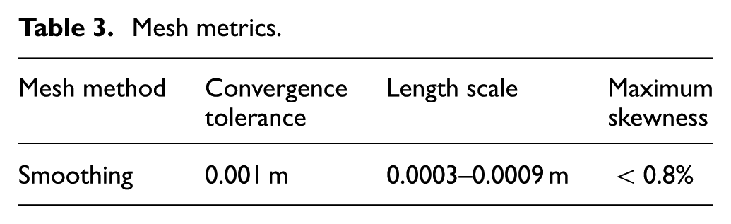
A numerical study has been carried out using the commercial CFD package Ansys FLUENT 18.0. Owing to the highly unsteady nature of flow in this exercise, sliding mesh has been performed in this work. The mesh and the mesh metrics are presented in Figure 9 and Table 3, respectively.
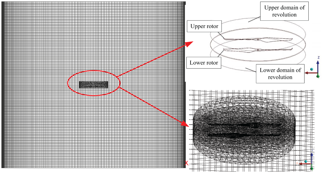
Mesh distribution.
Mesh metrics.
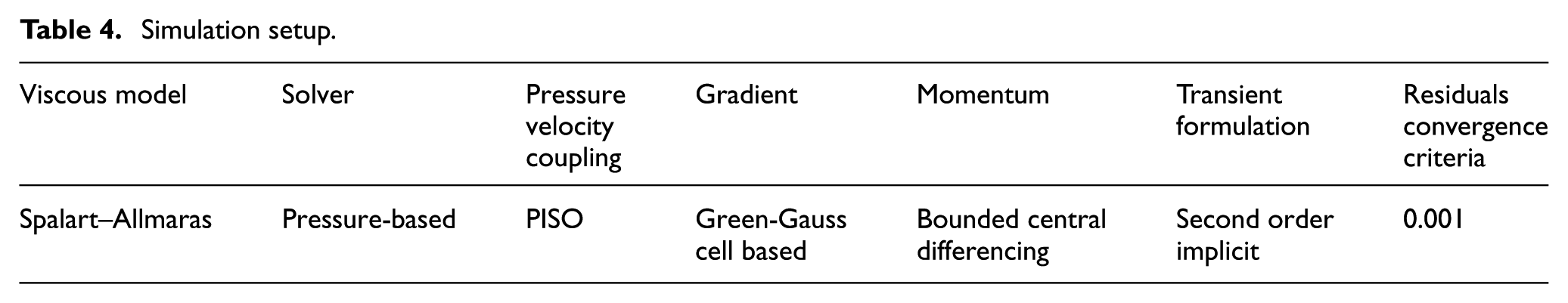
The mesh has a size of 4.3 million cells. The simulation setup is showed in Table 4.
Simulation setup.
CFD verification
This study has been performed with three-dimensional (3D) simulation using sliding mesh, which is a efficient way to visualize the variation of flow field since the experimental data are not intuitive enough to obtain some useful conclusions. 20 The simulation results were verified by comparing to experimental results as showed in Figure 10.
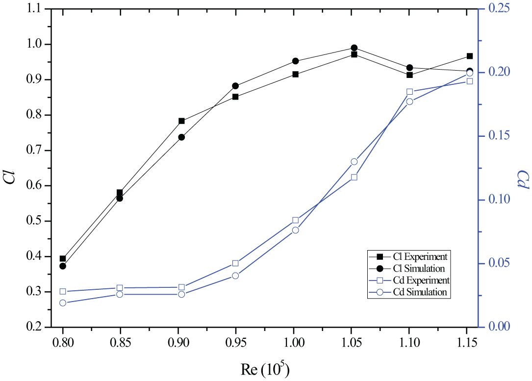
Comparison of experiment and simulation.
The comparison of Cl and Cd in experiment and simulation showed that they are generally in good agreement.
Streamline distributions
Streamline distribution of coaxial rotors is shown in Figure 11.
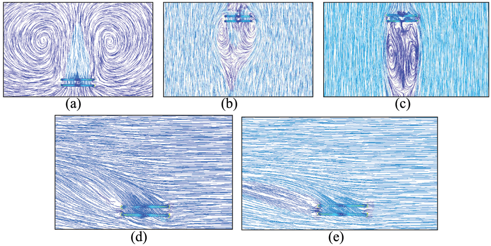
Streamline distribution: (a) without wind gust, (b) vertical wind – 2.5 m/s, (c) vertical wind – 4 m/s, (d) horizontal wind – 2.5 m/s and (e) horizontal wind – 4 m/s.
Streamline distribution of coaxial rotors without the wind gust is shown in Figure 11(a). It is clear that two uniform vortices are formed above the blade tip and the streamline is axial-symmetry. The streamline distribution which is affected by vertical wind is shown in Figure 11(b) and (c). The vertical wind first act on the upper rotor disk, and go around the blade tip subsequently. Part of the wind is suctioned between the upper and lower rotors. Due to the reverse rotation of two rotors, the aerodynamic interference between rotors is relatively complex. Compared to the regular vortices without the effect of wind gust, the vortices which are affected by vertical wind are extruded, deformed and transferred downward. When the wind speed increases, the extrusion and deformation get worse with a larger suction angle. Also, the mutual interference is more serious and the vortices continue to move downward and diffuse which may cause server vibration. 21 In addition, the streamline is stretched longitudinally and the axial flow is changed from circumferential flow to axial flow.
The streamline distribution that is affected by horizontal wind is shown in Figure 11(d) and (e). When the horizontal wind act on the rotor disk, the airflow directly moves to the blade tip. After the reverse rotation of the upper and lower rotors, the airflow gradually flows to the upper left of rotors, and is mixed with the horizontal wind. Compared to the horizontal wind of 2.5 m/s, amplitude of upward motion of the streamline is smaller to the case of 4 m/s, and the streamline distribution is more regular and uniform.
Based on the above analysis, the movement and deformation of vortices deteriorated the rotor performance in the vertical wind. However, the flow field in the horizontal wind was proved with a better performance without forming the large vortices, and the streamline distribution with small deformation is more regular and uniform.
Velocity distribution
Due to a higher air velocity, the vortices are easily shed from blade tip. Distributions of the velocity vector at blade tip affected by natural wind are shown in Figure 12.
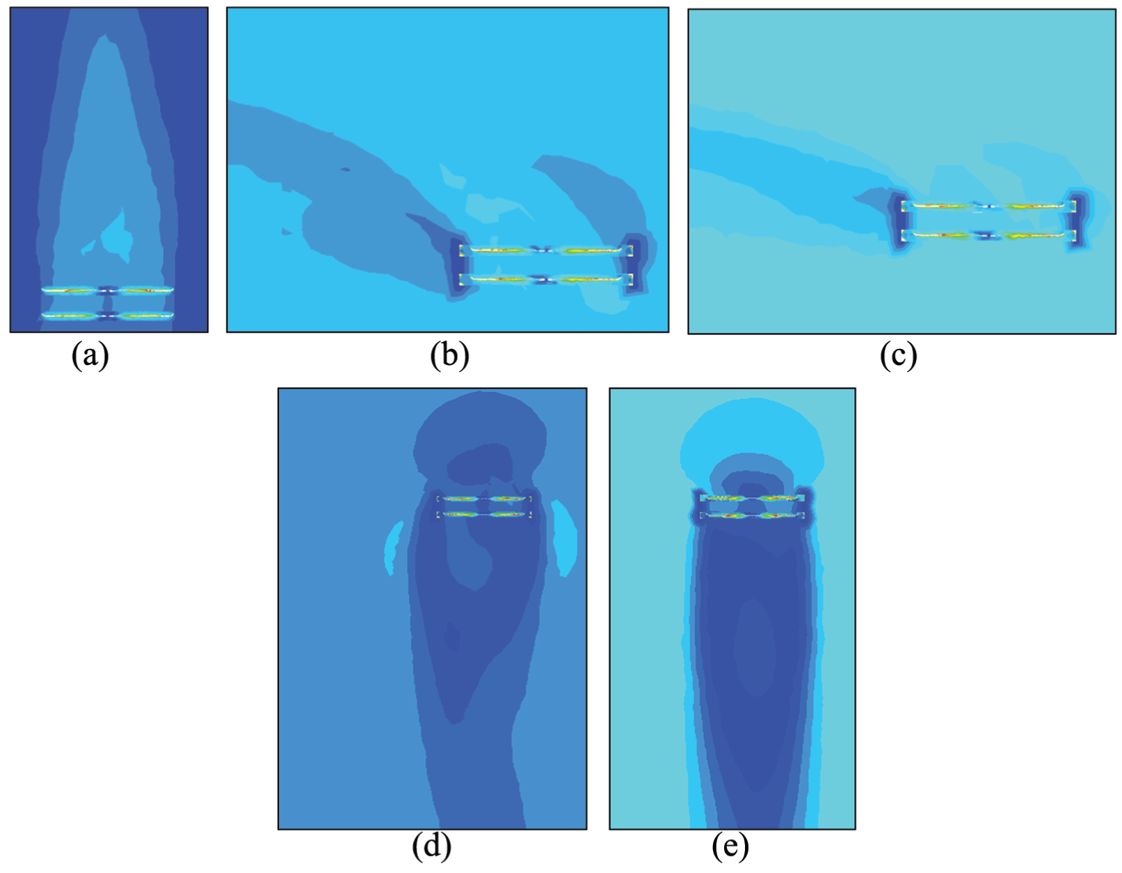
Velocity distribution: (a) without wind gust, (b) vertical wind – 2.5 m/s, (c) vertical wind – 4 m/s, (d) horizontal wind – 2.5 m/s and (e) horizontal wind – 4 m/s.
As is shown in Figure 12(a), without the effect of wind gust, the vortex is formed at blade tip of the upper and lower rotors. As is shown in Figure 12(b) and (c), with the vertical wind is introduced, vortices at blade tip gradually became incomplete and partially diffused as the wind speed increased. It is more obvious in a vertical wind, as shown in Figure 12(d) and (e), that the vortices are completely diffused by the light breeze. Therefore, vortices formed at the blade tip are more vulnerable to horizontal wind than the vertical one.
Conclusion
Both computational simulations and wind tunnel tests are performed on a coaxial rotor pair to verify the effect of the wind disturbances around hover condition. Following are conclusions obtained by comparing the test and simulation results:
Effect of the vertical wind is much obvious than the horizontal wind with lower thrust around 0.5 N and higher power increment around 2% at a higher RPM. This indicated that the coaxial rotors can effectively resist the wind disturbance at horizontal direction. Furthermore, aerodynamic performance of coaxial rotors is greatly improved when the speed of horizontal wind increased.
When a vertical wind is introduced, the original vortices between the coaxial rotors are squeezed by the strong axial flow along with the wind direction, and eventually begin to deform. Also, the overall streamline is longitudinally stretched and changed from circumferential flow to an axial flow. In addition, there is no large vortex generated in flow field with the horizontal wind, and the streamline distribution is regular with a little deformation.
The aerodynamic performance of coaxial rotors may be deteriorated by moving or deforming the vortices of the rotor pair. Also, compared with the vertical wind, vortices formed at the blade tip are more vulnerable and easily affected by the horizontal wind.
It should be noted that the CFD method in this paper only provides a means of visualizing the flow field since the experimental data are not intuitive enough to obtain some useful conclusions. Further study will involve both the PIV tests and CFD simulation for the octorotors with four coaxial rotor pairs.
Footnotes
Acknowledgements
The authors thank the Key Laboratory of Fluid Power and Intelligent Electro-Hydraulic Control (Fuzhou University), Fujian Province University, for applying the experimental field.
Declaration of conflicting interests
The author(s) declared no potential conflicts of interest with respect to the research, authorship, and/or publication of this article.
Funding
This project was supported by the National Natural Science Foundation of China (Grant No. 51505087 and 51775114), the State Scholarship Fund from China Scholarship Council (201806655008) and Fujian Provincial Industrial Robot Basic Components Technology Research and Development Center (2014H21010011).