
Abstract
The article aims to prove the effectiveness of the proposed unmanned air vehicle design (The Propulsive Wing) through numerical and experimental means. The propulsive wing unmanned air vehicle is a completely new class of unmanned air vehicle, making disruptive changes in the aircraft industry. It is based on a distributed cross-flow electric fan propulsion system. When the fan starts to operate, the flow is drawn from the suction surface, provided by energy through the fan and expelled out of the airfoil trailing edge (TE). This causes a significant lift increase and drag reduction with respect to ordinary aircrafts, making it perfect for applications requiring low cruise speed such as firefighting, agriculture, and aerial photography. In this early stage of the investigation, our main aim is to prove that this design is applicable and the expected aerodynamic and propulsion improvements are achievable. This is done through a two-dimensional computational fluid dynamics investigation of the flow around an airfoil with an embedded cross-flow fan near its TE. A scaled wind tunnel model of the same geometry used in the computational fluid dynamics investigation was manufactured and used to perform wind tunnel testing. The computational fluid dynamics and wind tunnel results are compared for validation. Furthermore, an unmanned air vehicle model was designed and manufactured to prove that the propulsive wing concept is flyable. The article shows that the aerodynamic forces developed on the cross-flow fan airfoil are not only functions of Reynolds number and angle of attack as for standard airfoils but also function of the fan rotational speed. The results show the great effect of the rotational speed of fan on lift augmentation and thrust generation through the high momentum flow getting out of the fan nozzle. Wind tunnel tests show that the suction effect of the fan provides stall free operation up to very high angles of attack (40 degrees) leading to unprecedented values of lift coefficient up to 5.8. The flight test conducted showed the great potential of the new aircraft to perform the expected low cruise speed and high angles of attack flight.
Keywords
Introduction and literature review
The propulsive wing concept has many advantages at both cruising and high angles of attack. At cruising angles of attack, cross-flow fan (CFF) shows a great capability of circulation control and the opportunity to be used for lift augmentation. Also at high angles of attack, by ingesting the low-momentum boundary layer along the suction surface and creating a large suction effect, the CFF eliminates the highly separated flow region on the suction surface that would be typically formed at such high angles of attack.
The idea of the application of a CFF in aviation was initially suggested by Ackeret, 1 as shown in Figure 1.
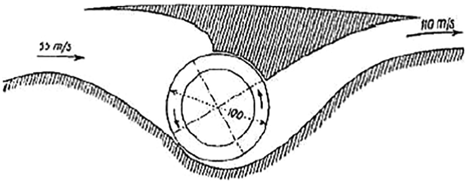
Boundary-layer blowing fan. 1
He suggested embedding a CFF inside the airfoil in order to re-energize the boundary layer flow; however, it was ineffective since there was no means to control the inlet and outlet flow directions. The aerodynamics of cross flow fans and how to use them in aircraft industry was investigated by a number of researchers.3–6 In 2006, the computational fluid dynamics (CFD) analysis of a modified Gottingen 570 thick airfoil with embedded cross-fan by Kummer and Dang 7 introduced a new propulsive airfoil concept not only for lift augmentation but also for thrust generation. A CFF with a raised inlet placed near the airfoil’s trailing edge (TE) draws in the low-momentum boundary layer on the suction side of the airfoil, energizes it, and expels it at the airfoil TE to fill in the wake region of the airfoil and generate thrust as illustrated in Figure 2. In 2008, The FanWing Company, directed by Dr/ Patric Peebles, 8 gave its first public flight demonstration during the international annual Unmanned Systems ParcAberporth Event in Wales.

Propulsive airfoil concept. 2
CFF airfoil section
Figure 3 shows the detailed geometry of the CFF airfoil section. A 34% thick modified Gottingen 570 airfoil section with integrated housing was scaled to fit a commercially available CFF. 20-bladed CFF rotor which is based on 6 cm diameter was used. Wall gaps were chosen to be 5% of the fan diameter (D), and the inlet and exit areas were fixed at 81% and 68% of the fan diameter (D), respectively. The wall gaps and inlet and exit areas were based on the work reported by Dygert and Dang. 9
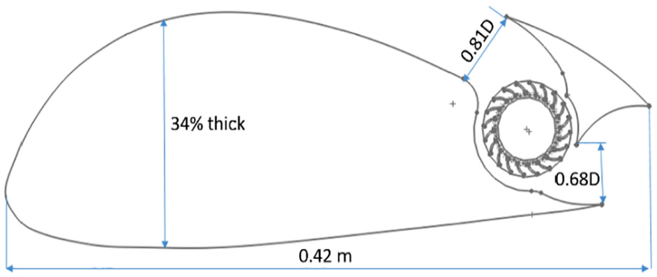
CFF airfoil model.
CFD overview
A commercial CFD software package ANSYS-FLUENT was used to model the flow over a CFF airfoil. Cases were setup at 5°, 10°, 20°, and 30° angles of attack for the geometric model described before with the flow velocity (U∞) of all cases set at 3.92 m/s (Rec = 1.0736 × 10⁵). The CFD simulation plan was developed to predict the performance of the CFF design over a range of speeds from 2000 to 4000 r/min. The simulation was considered two-dimensional (2D) to simplify the transient setup.
CFD setup
The simulation domain is a square domain of size (24c × 24c) shown in Figure 4. This domain was sufficient to obtain accurate results for our problem. The simulation domain is divided into three main regions: the outer domain, the rotor domain, and the fan interior domain.

Simulation domain mesh.
A hybrid mesh including both quad and triangular elements was used. The quad elements were used around the airfoil surface, the fan blades, and the fan housing to give accurate solution in near-wall regions. Tri-elements were used elsewhere for their flexibility and less time consuming for the entire mesh generation.
Smooth transition between quad-elements on surfaces and Tri-elements in the entire domain must be guaranteed to ensure that the solution is transferred properly through the different grid elements as shown in Figure 5.

Mesh details.
Each mesh was composed of 180,000 cells with only varying the airfoil angle of attack. Sliding mesh is used to allow for the rotation of the fan rotor domain with specified rotational speed while the other two domains are stationary, it allows for a transient calculation in which parts are actually moved each time step. Our problem is an IBVP (initial boundary value problem), so in order to start our solution both initial and boundary conditions should be imposed. A uniform velocity boundary condition was imposed at the domain inlet, and pressure outlet (P = Patm) was imposed at the domain outlet with both boundaries having a turbulent intensity of 1% and a turbulence viscosity ratio of 1%. The upper and lower boundaries were set as symmetry planes. For the initial condition, fluent hybrid initialization was used in which initial values for both pressure and velocity fields are assigned by solving the Laplace equation in the entire domain. A pressure-based solver is used. Second-order upwind discretization was used.
All runs were made in double precision mode. The k-ε turbulence model with enhanced wall treatment was used with y+ values ranging between 0 and 1 on all the surfaces in the simulation domain. Transient simulations were made using a time step corresponding to 1 degree of the CFF rotation. This time step was necessary to obtain accurate results and to capture all the changes that take place in the flow due to the fan rotation. Convergence was indicated by monitoring both lift and drag coefficients; when significant oscillations are ceased, convergence is reached. Also residuals were monitored and are decreased to at least 10–5 in all cases.
All cases were run on Lenovo Z5070 with the following specifications:
8 Processors Intel(R) Core(TM) i7-4510U CPU @2.00 GHz 2.6 GHz;
Installed memory (RAM):8.00 GB.
Number of iterations and simulation time increase with the angle of attack (α) as more separated flow exists with increasing α and the fan requires more time to completely reattach this separated flow to the airfoil surface, that is, condition becomes more severe. The average run time for each case was about 2–3 days.
Effect of fan on lift generation
In this section, we will discuss the effect of fan operation at different rotational speeds on lift augmentation. For standard airfoil sections, lift varies with the angle of attack but in our case the lift varies depending on both the angle of attack and the rotational speed of fan since the rotational speed of fan controls the degree of reattachment of the separated flow and hence lift augmentation. Figure 6 shows the variation of the lift coefficient with the angle of attack (α) for different rotational speeds.
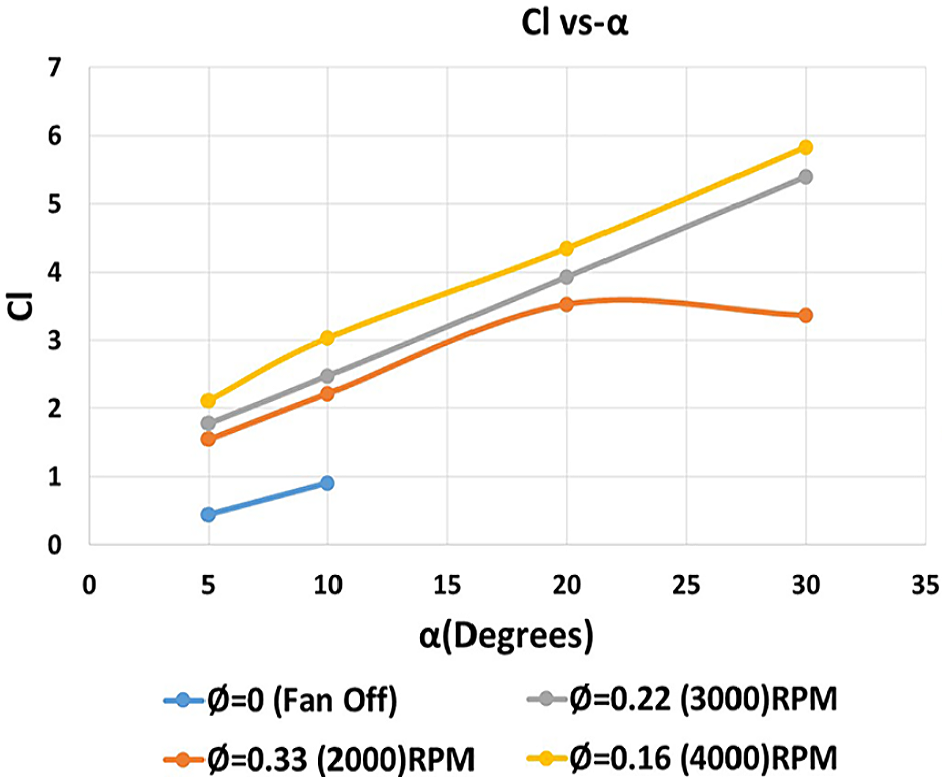
Cl versus α.
We can deduce that at a constant rotational speed, Cl is found to increase with the angle of attack (α), as long as the rotational speed of the fan is greater than the reattachment value. In case of 2000 r/min, the lift coefficient at α = 30° is less than that at α = 20° since the rotational speed of the fan is less than the reattachment value (i.e. at α = 30°, the rotational speed was not sufficient to fully reattach the massively separated flow). There is a noticeable lift augmentation at cruising angles of attack (5°, 10°) as the fan starts to operate at 2000 r/min which is the minimum rotational speed used. The percentage increase in Cl at 2000 r/min with respect to the fan off case is 240% at α = 5° and 144% at α = 10°. The CFF airfoil can achieve very high lift coefficients up to 6 at α = 30°. The highly generated lift allows unmanned air vehicles (UAVs) using a CFF airfoil to have a very low cruise velocity relative to the conventional ones.
The velocity ratio contours (velocity ratio = U/U∞) at 2000 r/min and various angle of attack (α) are shown in Figure 7, and we can see that for angles of attack (5°, 10°, 20°), the fan was able to fully reattach the separated flow and the lift coefficient was increasing, but for α = 30° it is noticed that the fan cannot fully reattach the massively separated flow and that is why the lift coefficient starts to decrease.

Velocity ratio contours for Ø = 0.33 (2000 r/min).
Effect of fan on thrust generation
In this section, we will discuss the effect of fan operation at different rotational speeds on thrust generation. Normal airfoil sections face drag only, but for CFF airfoil, thrust is generated. So we define net drag (Cdnet) which is the drag coefficient taking into account jet thrust (i.e. the component of jet that overcomes the drag). Figure 8 shows the variation of Cdnet with the angle of attack (α) for different rotational speeds. Negative values of Cdnet indicate thrust generation. It shows the capability of the CFF not only for drag elimination but also for thrust generation. At a constant angle of attack, we can see that as the rotational speed increases, more thrust is generated.

Cdnet versus α.
The intersection of a constant rotational speed curve with the x-axis indicates the angle of attack at which the Cdnet = 0 and this means that the generated thrust is equal to the drag.
Figure 9 shows the velocity ratio contours at 4000 r/min and angles of attack (5°, 10°, 20°, 30°). It is noticed that at a constant rotational speed, as the angle of attack (α) increases, the jet component that overcomes the drag decreases and also the maximum velocity ratio decreases as the angle of attack increases and that is why the (Cdnet) value increases (i.e. tends to being positive).

Velocity ratio contours for Ø = 0.16 (4000 r/min).
It is also noticed that the maximum velocity ratio decreases by 16% as the angle of attack increases from 5° to 30° at 4000 r/min.
Experimental overview
The main aim of the conducted experimental study is not only to validate the numerical results obtained but also to prove the ability of the electrically operated fan to enhance lift and also generate thrust in the real operating conditions. A key advantage of the experiment is that it tests the mechanical limitations of the proposed design. The main limitations imposed on our experiment are the available fan diameter and motor power. These two factors greatly affect the model dimensions in addition to the maximum fan rotational speed.
Experimental setup
The fan used is 45 mm in diameter which resulted in a scaled wing model having a chord length of 308 mm. The wing model in Figure 10 is designed to span the entire test section of the small 2D wind tunnel shown in Figure 11 available at the Aerodynamic Laboratory, Aerospace Department, Cairo University.

Wing model.
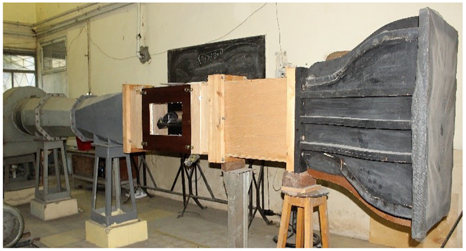
2D wind tunnel.
The tunnel test section is 20 cm in width and 50 cm in height and the tunnel maximum free stream velocity is 24 m/s, the fitting of the ports are according to Barlow et al. 10
The model shown in Figure 12 is fitted with 21 pressure ports equally distributed on the upper and lower surfaces with no ports in the fan or housing regions.

Wind tunnel model pressure ports distribution.
The wind tunnel speed is measured using a pitot-static tube. The device used to measure the pitot-static tube pressure readings in addition to the pressure distribution on the wing is a digital manometer shown in Figure 13 having an accuracy of 0.1 pa that was sufficient for our tests. The motor used is (EMAX XA2212) 1400 KV brushless motor whose rotational speed is controlled using an electronic speed controller (ESC) and a servo tester. The maximum rotational speed obtained using this motor is 7200 r/min. The rotational speed of the fan is the main parameter in our study; therefore, we need to have a live reading of the rotational speed throughout the test, and this is done using a digital tachometer.

Digitron digital manometer and digital tachometer.
The arrangement in Figure 14 is mounted on a specially designed tunnel wall for this experiment that allows perfect alignment of the model and accurate guide lines for the angle of attack.

Experimental arrangement.
Finally, two main experiments are conducted using the previously mentioned experimental setup, which are as follows:
Measuring the static pressure distribution over the surface of wind tunnel model and comparing the experimental and numerical results.
Studying the effect of the independent parameters (α, Rec, φ) on the pressure distribution.
Effect of angle of attack on Cp distribution
For conventional airfoils, increasing the angle of attack increases the area under the Cp curve. The area under this curve is the normal force coefficient which is further resolved into lift and drag coefficients. At zero lift, both the upper and lower surfaces have both positive and negative lifts. With increasing angle of attack, the upper surface increases in proportion until it finally is lifting about 70% of the total. Therefore, increasing the angle of attack increases the lift generated until the stall angle of attack is reached at which the lift dramatically decreases and the Cp curve collapses. The same trend exists for the propulsive airfoil yet the existence of the fan, as mentioned before, delays the separation. This provides stall free operation up to very high angles of attack (40–45 degree). In Figure 15, the experiment we conducted shows that the amount of lift generated (the area under the Cp curve) continuously increases with the increase in the angle of attack (i.e. there is no trace of stall behavior).
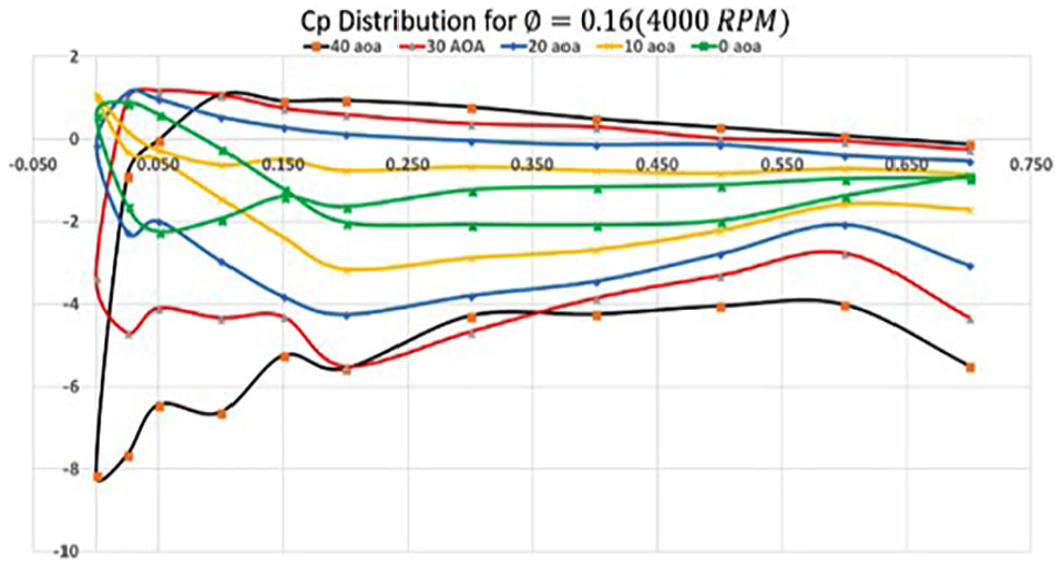
Cp distribution for Ø = 0.16 (4000 r/min).
Validation with the CFD results
We are concerned by validating the numerical results obtained. Validation of the two different cases is shown in Table 1.
Results validation.

CFD: computational fluid dynamics.
To make sure that we have the same value of the fan flow coefficient and Reynolds number, the wind tunnel model has a fan diameter of 45 mm while in the CAD model used for the CFD analysis the fan was 60 mm in diameter. This means that maintaining the same values of

Cp distribution for Ø = 0.33 (2000 r/min).
Figure 17 shows our second comparison case, and we can see that the CFD data agrees well with the experimental data, especially on the pressure surface. It is noticed that the region near the TE on the suction surface just before the fan shows a significant disagreement between both the CFD data and the experimental data. This disagreement is due to the highly separated flow at such a high angle of attack that cannot be captured well by the turbulence model.
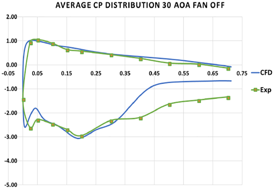
Cp distribution for α = 30° (Fan Off).
UAV model overview
A 1.35 m span and 0.42 m chord UAV model is designed and manufactured to prove the functionality of the propulsive wing concept (Figure 18). The aircraft model is powered by two CFFs integrated span-wise near the TE of the wings. The fans are driven by O.S. OMA-5020-490 brushless motor. The power is transmitted from the motor to the shaft carrying the CFFs through a pulley-belt mechanism. The model has high tail configuration to avoid the large downwash from the fans.

UAV CAD model.
According to the availability in the market, three CFFs were bought and assembled together using keys on a 10 mm aluminum shaft (Figure 19). Each fan has a diameter of 6 cm and a 20 cm span. The shaft diameter is decreased in between the fans for weight reduction.

CFF assembly.
The two shafts are connected together using a couple and a key so that the two shafts and the six fans rotate together as one unit (Figure 20). This eliminates the problem that one of the fan assemblies rotates with a rotational speed different from the other side.

Couple and key.
CFFs configuration and assembly
The necessity of using the pulley-belt mechanism to drive the shaft arises from the need of keeping the aircraft CG in a forward location for stability (Figure 21). Most of the aircraft weight is concentrated near the TE. Without this mechanism, the motor would be mounted directly to the shaft near the TE, which will move the CG further backwards.

Pulley-belt mechanism.
The actual UAV model shown in Figure 22 was the final model used in the conducted flight test (Figures 23–25).

UAV actual model.

Aircraft taxing.

Aircraft takeoff.

Aircraft after landing.
Flight test
Date and time: 10 July 2018, 4:00 pm.
Location: Faculty of Engineering Sheikh Zayed Campus.
Weather condition: temperature 35°C, wind speed 7 knots.
Flight test report
The aircraft showed the ability of taxing on the ground.
The aircraft was able to takeoff.
The takeoff distance was more than expected due to unpaved runway.
Due to high wind speed, the pilot lost control of the aircraft.
After the crash, there was no critical damage in the aircraft’s structure; only the skin of the left wing was removed.
The produced thrust was enough to accelerate the aircraft on the ground and also takeoff.
The ailerons were not effective resulting in the lost control of the aircraft.
The aircraft’s structure is rigid enough to withstand strong impacts.
Conclusion
The study succeeded to apply and prove the benefits of embedding a CFF in a thick airfoil section in order to be used for thrust generation, lift augmentation, and circulation control. The CFD simulations and wind tunnel tests showed that the propulsive wing can fly up to an angle of attack of
Footnotes
Appendix 1
Acknowledgements
The propulsive wing project team would like to thank everyone who offered help throughout the year. We would like to express our deepest gratitude and sincere thanks to Prof. Dr Mohamed Madbouli due to his instructive supervision, continuous guidance, and valuable instructions. We would also like to thank Prof. Mohamed Kahlil and Prof. Osama El-Said for the generous advices and offering of all facilities. Great thanks to Eng. Sherif Azmy for the strong mechanical and technical support. Without his creative thinking and valuable suggestions, the manufacturing of the UAV model would have been extremely difficult. Also thanks to the great staff of the Aerospace Department Cairo University (Eng. Nabil, Eng. Bayram, Eng. Diaa, Eng. Mahmoud Gomaa) who were always supportive and helped us whenever we needed help. Thanks for the excellent technician and person Mr Sameh Said. Finally, thanks to our parents who were supportive until the last day. Thanks for believing in us and for being always there. This article was present at 30 Proceedings of ICFD13: Thirteenth International Conference of Fluid Dynamics, 21–22 December, 2018, Steigenberger Hotel El Tahrir, Cairo, Egypt.
Handling Editor: Ahmed Abdel Gawad
Declaration of conflicting interests
The author(s) declared no potential conflicts of interest with respect to the research, authorship, and/or publication of this article.
Funding
The author(s) received no financial support for the research, authorship, and/or publication of this article.