
Abstract
The flight envelope plays an important role in flight safety. The concept of posing the flight envelope as a region of attraction is explored further, and it is investigated whether the stable manifold for the region of attraction computation is an efficient method for determining envelope. The stable manifold describes the flight dynamic envelope of an aircraft in an explicit representation, which means that the computation needs to be done only on the envelope, not the entire state space. In this paper, the stable manifold is computed by using a fast method which reduces the computation to solving a system of partial differential equation. Then, the stable manifold grows in the way of advancing front mesh generation framework. The stable manifold is then applied to the envelope determination of a nonlinear F-16 model. The result is compared to the results obtained with the level set method, demonstrating that the stable manifold provides a feasible and accurate result to the dynamic envelope. The proposed method is then used to investigate the effect of actuator failure on the flight safety. The proposed method can also be used as a safety assessing tool during the design phase of an aircraft.
Introduction
Safety has always been of paramount importance in aviation. Admirable efforts have been made to prevent aircraft accidents. Statistics have shown that many fatal aircraft accidents are related to aircraft loss of control (LOC).1,2 The LOC accidents could be traced back to a similar reason: the flight envelope violation. When an aircraft is impaired or encounters upset conditions, for example, a jammed actuator, sensor malfunction, or encounters icing condition, the flight envelope reduces severely. Due to lack of knowledge of the severely reduced flight envelope, the pilots may carry out unwise operations, which could lead to LOC accident or even crash, for example, the EL AL flight 1862 accident in 1992 3 and the ATR accident of 1994. 4 Post-crash analyses showed that if the reduced flight envelope has been known to the flight crew and the crew manipulate the aircraft wisely, the crash may be avoided. 5 These examples clearly show that the envelope determination is significant for flight crew to deal with fatal accidents. Moreover, envelope determination is the essential tool for the envelope protection system which helps the pilots to keep the aircraft within the flight envelope.
The conventional flight envelope describes the area of altitude and airspeed where an airplane is constrained to operate. This envelope is subject to the thrust limit, lift limit and structural strength limit of an aircraft. It is usually determined by wind tunnel tests and flight test experiments which can be quite expensive. Moreover, in the conventional flight envelope, only constraints on steady or quasi-steady conditions are considered. Conventional envelope protection schemes, which protect for stall, exceeding overspeed, limit angle of attack, and load factors, determine the limitations of aircraft states separately.6,7
However, the coupling between the states will affect the stability and safety of the aircraft, 8 especially in the upset conditions. Therefore, the flight envelope should be determined taking coupling multi-factors such as angle of attack, pitch angle, pitch rate, and velocity into account. Wilborn and Foster 9 employed five two-dimensional envelopes to define LOC quantitatively. These five envelopes take some critical flight parameters into account. The coupling effect between these parameters is reflected by two-dimensional curves. van Oort proposed that the safe flight envelope can be defined by the intersection of three envelopes: the dynamic envelope, the structural and comfort envelope, and the environmental envelope. 10 The structural and comfort envelope and the environmental envelope are external constraints on the flight envelope and can be quantified easily. The dynamic envelope is the region of aircraft state space in which the aircraft can be safely controlled, and no LOC events can occur. It represents the constrains dictated by the aerodynamics and kinematics of the aircraft, and it is internal to the aircraft itself and depends on its dynamic behavior. 11
Recently, more and more researchers have begun to use the theories of dynamical systems to determine the dynamic envelope based on the nonlinear dynamic equation of aircraft. The nonlinear problem in flight dynamics has been paid attention to at the beginning of aviation technology, but due to the limitations of analytical tools and computer level at the time, there has been a lack of nonlinear methods to determine the safety envelope of aircraft. 12 The introduction of bifurcation and continuation methods has brought important breakthroughs in determining safe envelope.13,14 The bifurcation and continuation methods can calculate all equilibrium states corresponding to different control inputs and can analyze the stability of the equilibrium state. This method can be used in the design phase of aircraft to verify flight control laws and flight envelopes.8,15–18 The bifurcation methods provide many ideas for other nonlinear methods for determining the safe envelope. For more detailed description of bifurcation theory applied to flight the dynamics, the interested reader is referred to Cummings, 17 Khatri et al., 19 Shi and Fan, 20 and Xin and Shi.21,22 However, the bifurcation theory and the continuation methods cannot intuitively give a safe area in flight state space.
The theory of reachable set analysis is a useful tool in safety verification of dynamic systems 23 and has been applied to estimate the flight dynamic envelope.10,11,24 The reachable set is a region of the state space which can be reached from an initial or target set of states. In the flight dynamic envelope estimation problem, the initial or target set is posed as a set of safe states, for example, a set of trim points. 25 Pandita et al. 26 applied region of attraction (ROA) analysis to NASA Generic Transport Model (GTM) dynamic flight envelope assessment. The ROA analysis offers the ability to take coupling multi-factors into account. It can determine a safe envelope around operating trim point. With the ROA method, a preliminary flight envelope can be obtained from the computational fluid dynamics (CFD) model of the aircraft during design phase. This can play an important role to check whether the design meets the requirements. Moreover, the ROA method can also be used for controller design to check whether the closed-loop system has enough stability under the upset condition. However, in Pandita et al., 26 the ROA is estimated by the largest ellipsoid contained in the ROA. This can lead to serious conservative result. In this paper, we will improve this by using stable manifolds to reduce the conservatism.
The reachable set has proven to be the zero sublevel set of the viscosity solution of a particular time-dependent Hamilton–Jacobi partial differential equation (HJ PDE).27,28 The level set method has been investigated extensively in solving the HJ PDE. 29 The level set method employs an implicit representation of the flight dynamic envelope. In other words, the flight dynamic envelope is defined by the isocontour of some function which is defined throughout the state space. To achieve a given level of accuracy, the state space needs to be discretized into the same level size grid in each dimension, and the solution is calculated on each grid. The primary weakness of level set method is the exponential growth of computational cost as the system dimension increases.
In this paper, the stable manifold is employed to construct the exact ROA which represents the flight dynamic envelope. Contrary to the level set method, the stable manifold employs an explicit representation of the flight dynamic envelope. Consequently, the computation needs to be done only on the envelope, not the entire state space. Hence, it is much more efficient than the level set method, which will be discussed in more detail in the fifth section. This research is motivated by our previous work, in which we tried to estimate the flight dynamic envelope based on differential manifold theory. 30 In this paper, we aim to propose method for determining the flight dynamic envelope efficiently. The main contributions of this research are the application of the stable manifold to flight envelope determination. To assess the feasibility and efficiency of flight dynamic envelope determination via stable manifold, it is implemented for the nonlinear F-16 model. Furthermore, the proposed method is compared with the level set method.
The organization of this paper is as follows. In section “Stable manifold,” the essential knowledge of the stable manifold is introduced. The dynamic model of the F-16 is proposed in section “Longitudinal dynamics of the F-16.” In section “Dynamic envelope determination,” the stable manifold is applied to determine the flight dynamic envelope of the F-16 model. Discussions on the proposed method are presented in section “Discussion,” where the proposed method is compared to the level set method and applied to investigate the effect of actuator failure on the flight safety. Finally, conclusions are drawn in section “Conclusion.”
Stable manifold
Consider an autonomous nonlinear system modeled by the ordinary differential equation

where
A state point
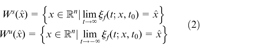
For an asymptotically stable equilibrium point (ASEP)
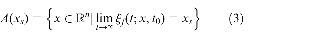
The boundary of ROA is denoted by
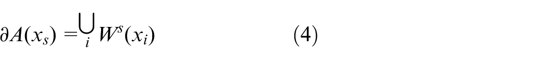
For an equilibrium point
For an aircraft, the ASEP
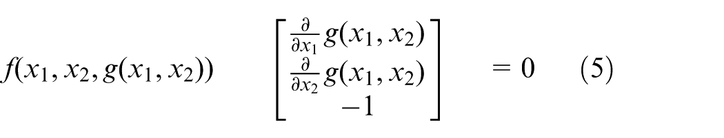
In the PDE approach, the invariant manifold grows in the way of advancing front mesh generation framework.43,44 The stable manifold is initially approximated by a small circle located in
The essence of the dynamic envelope is the area in the flight state space in which the aircraft can operate safely. ROA methods offer the ability to predict a stable set in state space around a given trim point. Therefore, the ROA can be used to assess dynamic flight envelope of the aircraft. A typical application scenario could be an aircraft trimmed for cruise flight experiencing an upset condition due to an atmospheric phenomenon. It is vitally important to know if such an upset condition could potentially destabilize the aircraft without a chance of recovery. There are many methods for estimating the ROA, most of which are based on the Lyapunov function and are largely conservative. As can be seen from the introduction in this section, the ROA can be accurately calculated from the stable manifold. In addition, the PDE algorithm can be used to calculate stable manifold quickly and efficiently. Based on this, we can come up with a method to determine the flight dynamic envelope via stable manifold. First, look for the UEPs on the envelope by numerically integrating the vector field. Then, we compute the stable manifolds of these UEPs with the PDE approach. Finally, the flight dynamic envelope with these stable manifolds is constructed.
Longitudinal dynamics of the F-16
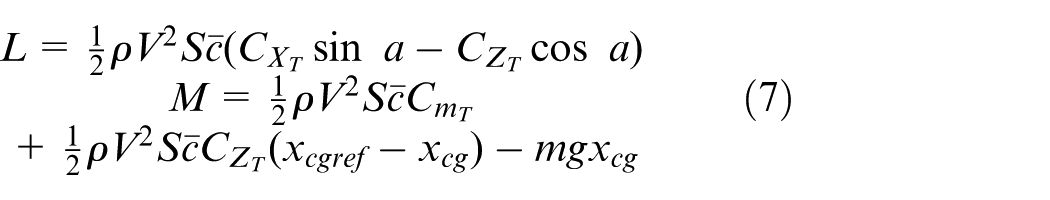
Determination of the dynamic envelope is computationally expensive in higher dimensions for both reachability calculation and stable manifold calculation. Moreover, the visualization of high-dimensional envelope is challenging. Therefore, in this paper, only the longitudinal dynamics is considered. In the subsequent discussion, we will present examples based on the F-16. For convenience of visualization, the complexity of the model is reduced by only considering the longitudinal motion for aircraft at a constant airspeed, 21 and then, the longitudinal dynamics of the F-16 can be described by
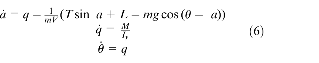
where
where
The altitude and speed have effects on the aerodynamic parameters. If these impacts are considered, the results will be more comprehensive. However, if the altitude and speed of the aircraft are considered, the system equation is five-dimensional. For systems higher than three-dimensional, the calculation of stable manifold is quite expensive, and visualization of stable manifold is challenging. We tried to calculate the stability region of a five-dimensional system in Qu et al. 47 However, in order to ensure that the calculation can be completed in an acceptable time, we have to sacrifice the calculation accuracy. In addition, the visualization of the results is not ideal and it is not convenient to analyze the effects of icing in a vivid manner. In addition, the typical application scenario could be an aircraft trimmed for cruise flight, during which the altitude and speed of the aircraft do not change significantly. Therefore, this paper focuses on the angle of attack, pitch angle, and pitch rate in the longitudinal dynamics.
The proportional–integral–derivative (PID) controller is the most used control low in the flight control engineering. The proposed method in this paper can be used to check whether the aircraft with PID controller has enough stability under the upset condition. The integral and derivative calculators will introduce additional state into the system, which will increase the dimensions of the system, resulting in expensive computational costs. To demonstrate the feasibility of the proposed method, a simple proportional controller which takes the actuator saturation into account is employed

where
Dynamic envelope determination
With flight altitude 4000 m and airspeed V = 86 m/s, the aircraft has two equilibrium points: the trim point SEP
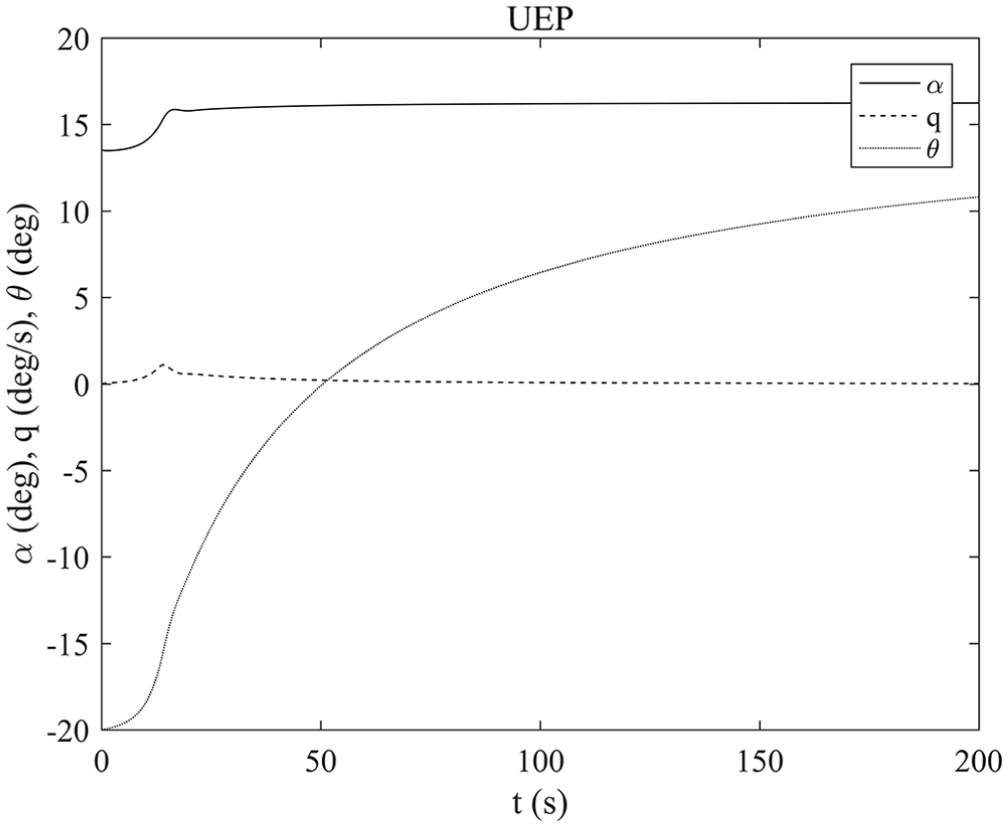
Unstable manifold of the UEP in time domain.
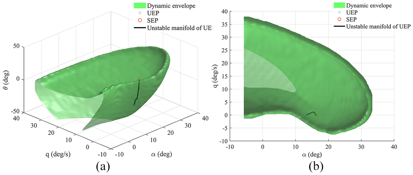
Flight dynamic envelope determined via stable manifold: (a) three-dimensional view and (b) side view.
The F-16 model in this paper does not use the leading-edge flap. Furthermore, the longitudinal and lateral motions are decoupled. The aerodynamic data are only valid for
The correctness and accuracy of the dynamic envelope can be verified by the brute force approach. Making discrete the state space to grid, the trajectory from each grid point is computed. If a trajectory converges to the SEP, then the corresponding grid point is in the dynamic envelope, otherwise it is outside the envelope. In Figure 3, the red circles are grid points whose trajectories converge to the SEP, while the gray crosses are grid points those do not. It is clear in Figure 3 that the envelope obtained by the proposed method is the interface between the two kinds of grid points.
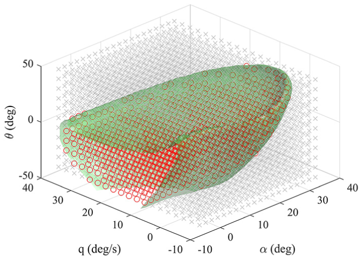
Verification of the correctness and accuracy of the dynamic envelope.
Discussion
The level set method has been widely used to determine the flight dynamic envelope. In the level set method, the dynamic envelope can be described by the level set of an implicit function
where
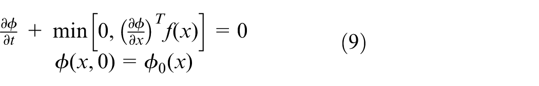
Figure 4 shows the computation of the dynamic envelope with the level set method. The terminal condition is set as the red surface A in Figure 4. Consequently, a sequence of dynamic envelope estimate is obtained in Figure 4. Surface D is the estimated envelope obtained after 15 s of evolution. Each estimate is contained in the green transparent surface which is the envelope obtained by the stable manifold. With the increase in evolution time, the results of the level set method will get closer to the result of the proposed method. Comparing the dynamic envelope obtained by the proposed method with the level set method, we can find from Figure 4 that the proposed method carries out a feasible and accurate dynamic envelope determination. Furthermore, in the level set method, the implicit function
Comparison with the level set method: (a) dynamic envelopes in three-dimensional view and (b) dynamic envelopes in the
The proposed method can be used to investigate the effect of the actuator failure on the flight safety. In Figure 5, the blue surface is the dynamic envelope obtained by the proposed method with reduced elevator deflection capability,
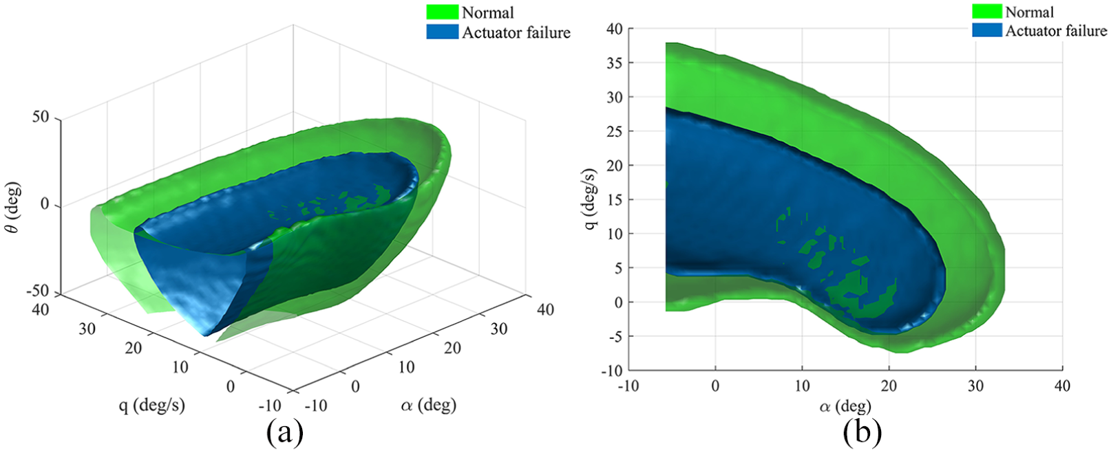
Effect of the actuator saturation on the flight dynamic envelope: (a) three-dimensional view and (b) side view. The green transparent surface is the dynamic envelope of the normal aircraft. The blue surface is the dynamic envelope with reduced elevator deflection capability,
Conclusion
In this paper, the stable manifold is employed to determine the flight dynamic envelope. Taking the F-16 model as an example, the proposed method turned out to be feasible and accurate. Compared with the level set method, the stable manifold method has higher computational efficiency. The proposed method can be used during the design phase of aircraft to assess the safety of specific flight state or to assess the stability of the flight controller. Furthermore, it can provide knowledge of the post-failure dynamic envelope which is extremely important for guaranteeing safety. The method also has some drawbacks needing further investigation. The construction and visualization of high-dimensional envelope is challenging. The future work includes analyzing the equilibrium points automatically, computing the stable manifold automatically and developing visualization methods for higher dimensional systems.
Footnotes
Acknowledgements
The authors would like to thank the editors and the anonymous reviewers for their constructive comments and suggestions that have improved the quality of this paper.
Declaration of conflicting interests
The author(s) declared no potential conflicts of interest with respect to the research, authorship, and/or publication of this article.
Funding
This work was supported by the National Program on Key Basic Research Project (973 Project) under grant number 2015CB755805, and the National Natural Science Foundation of China under grant number 61374145.