
Abstract
In order to realize maneuver combat in the modern warfare, some special military vehicles require the ability of determining their position and orientation rapidly and accurately, and the position and orientation system should be highly autonomous and have strong anti-jamming capability. So a high-accuracy independent position and orientation method for vehicles that utilizes strapdown inertial navigation system/Doppler radar is presented in this article. Laser gyroscopes in strapdown inertial navigation system and Doppler radar are adopted to develop a dead-reckoning system for vehicles. Subsequently, the attitude, velocity,and position-updating algorithms of dead-reckoning system are designed. The error sources of dead-reckoning system are analyzed to establish the system error model, including the attitude error equations of the mathematical platform, velocity error equations, and position error equations. The errors of strapdown inertial navigation system and deadreckoning system are selected as system states of the integrated position and orientation method. The difference between the attitude output of strapdown inertial navigation system and that of dead-reckoning system, and the difference between the position output of strapdown inertial navigation system and that of dead-reckoning system are chosen as the measurements of integrated position and orientation. Then, Kalman filter is adopted to design the filtering algorithm of integrated position and orientation. In the end, the integrated position and orientation method is validated by simulation experiment and vehicular experiment. The experimental results show that strapdown inertial navigation system/Doppler radar integration can realize accurate positioning and orientation for a long time, and the accuracy of attitude/position integration mode is significantly higher than that of velocity/position integration mode. Therefore, the former integration mode is more suitable for accurate position and orientation for vehicles.
Keywords
Introduction
Some special military vehicles, such as command vehicles, launcher vehicles, and armored vehicles, require the ability of determining their position and orientation rapidly and accurately, so as to realize maneuver combat in the modern warfare.1,2 The position and orientation system should be highly autonomous and have strong anti-jamming capability in a combat environment.
The inertial navigation system (INS), which is a known type of autonomous navigation system with strong anti-jamming ability, is well suited for military purposes. However, the navigation errors of the pure INS accumulate over time. Therefore, INS cannot achieve high-accuracy position and orientation for extended periods of time. Thus far, integrated navigation equipment, such as INS/satellite,3–7 INS/odometer,8–10 INS/vision 11 integrated navigation systems, has been used to assist INS to achieve high-accuracy position and orientation, as presented in many papers. The INS/satellite integrated navigation system has excellent characteristics, such as high accuracy, low cost, strong maneuverability, and other features. 12 However, the satellite signals can be easily jammed or shielded in wartime,13,14 and the signal transmission may also fail between tall buildings or in tunnels, which would lead to the failure of positioning. Therefore, this means that INS/satellite integrated system has weak anti-jamming ability and poor autonomy, both of which limit its application in the military field. In contrast, INS/odometer integrated system offers the advantages of strong autonomy, good anti-jamming capability, and high accuracy. This integration approach is widely used in land weapon vehicles since it can provide relatively high-accuracy navigation information as well as remain autonomous. However, vehicle slipping or gliding is known to affect the odometer reading, which will introduce large measurement errors,15,16 and reduce the accuracy of position and orientation. In order to reduce INS error accumulation, vision-aided INS with point and vertical line observations for land vehicle applications were developed. 11 This method can effectively improve the accuracy of the attitude and position estimation and has the advantages of strong autonomy and anti-jamming capability.
Continuous positioning was achieved by developing INS/odometer/satellite integration navigation method based on particle filtering (PF), 17 and the performance of this method was examined using a land vehicle on road test. The test results demonstrated that this method achieved superior performance during global positioning system (GPS) becoming invalid and improved the position accuracy. Thus, INS/odometer/satellite integrated system has been considered one of the most attractive methodologies for ground vehicle navigation. However, once satellite navigation fails for long time, the accuracy of this approach will deteriorate gradually with time. To overcome this limitation, a novel ground vehicle navigation system based on an integrated INS, GPS, odometer, and vision data was proposed. 14 Experiments demonstrated that this integrated navigation approach improved the position accuracy by over 30% during simulated GPS outages.
Vehicular Doppler radar, which is based on the Doppler effect, is used to measure the vehicle velocity by calculating the difference between the frequencies of the transmitted and echo waves. Vehicular Doppler radar offers advantages such as high accuracy, absence of velocity-accumulated errors, continuous output, strong anti-jamming ability, and strong independence.18,19 In particular, Doppler radar could avoid the measurement errors caused by vehicle slipping or gliding. A pair of Doppler radars was used to estimate the running paths of vehicle accurately. 20 Since the drift errors of INS are inevitable and grow over time, Doppler velocity log (DVL) is used to aid INS to restrain its error growth. Therefore, INS/DVL integration is a good approach for autonomous underwater vehicle (AUV) navigation21–24 and is currently being used underwater. Considering the aforementioned findings, this paper adopts Doppler radar and laser strapdown inertial navigation system (SINS) to develop an integrated position and orientation system for vehicles, for which an accurate integrated position and orientation algorithm was researched. The advantage of this integrated system is its ability to achieve rapid accurate position and orientation on land, with strong autonomy and good anti-jamming ability.
This paper describes the basic principles of this accurate integrated position and orientation method. Section “SINS/Doppler radar integrated position and orientation scheme” describes SINS/Doppler radar integrated position and orientation scheme and presents the schematic diagram. The laser gyroscope/Doppler radar dead-reckoning algorithm is provided in section “Dead-reckoning algorithm based on laser gyroscope/Doppler radar,” which is based on the angle increment output of the laser gyroscope and the velocity output of the Doppler radar, section “Error models of the laser gyroscopes/Doppler radar DRS” analyses the error sources of dead-reckoning to establish the error models of dead-reckoning system (DRS), including the attitude error equations of the mathematical platform, velocity error equations, and position error equations. Section “Filtering algorithm of the integrated position and orientation based on SINS/Doppler radar” presents the filtering algorithm of SINS/Doppler radar integrated position and orientation system, including the state equations and measurement equations for integrated position and orientation. Then, Kalman filter is adopted to design the filtering algorithm of the integrated position and orientation system in section “Filtering algorithm of the integrated position and orientation based on SINS/Doppler radar.” The experimental results are presented and analyzed in section “Experimental results,” and conclusions are drawn in section “Conclusion.”
SINS/Doppler radar integrated position and orientation scheme
The east–north–up frame is used as the navigation frame (n frame), and the right–front–up frame is considered as the vehicle body frame (b frame). Both the laser SINS and Doppler radar are installed on the vehicle. After navigation calculations, the laser SINS outputs the attitude, position, and velocity information of the vehicle, and the Doppler radar outputs the velocity of the vehicle in real time.
During the position and orientation process, laser gyroscopes in SINS and Doppler radar are used to construct the laser gyroscope/Doppler radar DRS, and the attitude and position information of the vehicle can be calculated. The difference between the attitude output of SINS and that of DRS, and the difference between the position output of SINS and that of DRS are chosen as the measurements of integrated position and orientation. Then, these measurements are sent to the integrated position and orientation filter. After the filtering calculation, the real-time estimates of system states (i.e. system errors) are calculated and used to correct the errors of SINS and DRS in real time. Finally, the outputs of the corrected SINS are considered as the outputs of SINS/Doppler radar integrated position and orientation system, including the attitude, velocity, and position of the vehicle. A schematic diagram of SINS/Doppler radar integrated position and orientation process is shown in Figure 1.
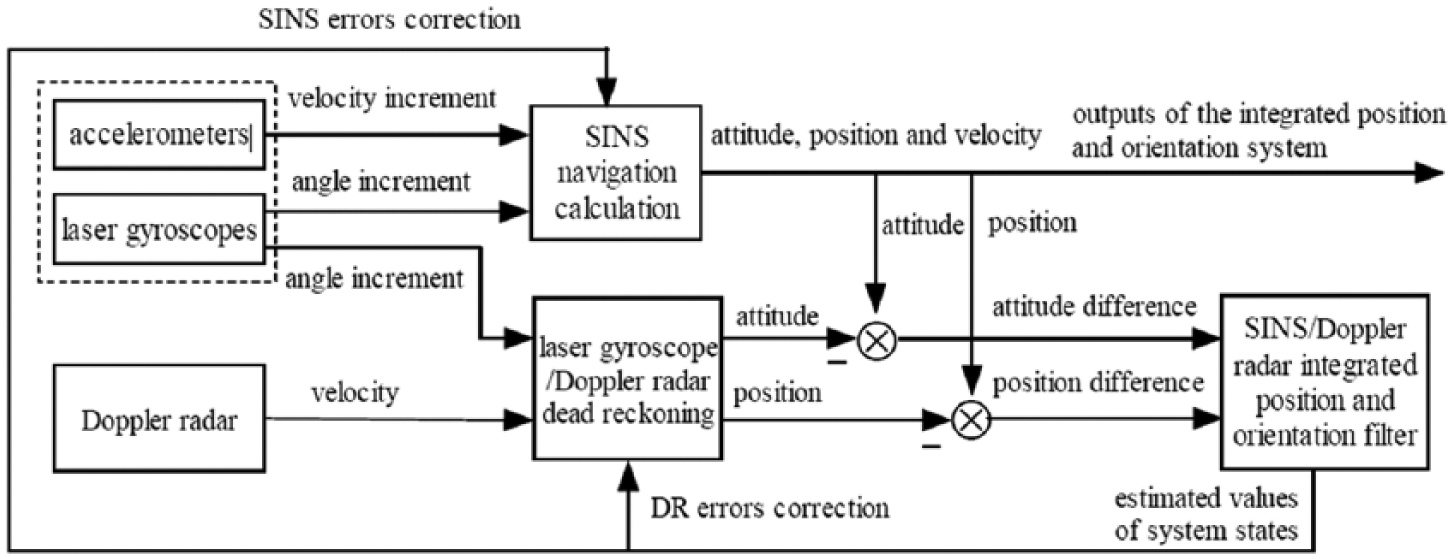
Schematic diagram of SINS/Doppler radar integrated position and orientation.
Dead-reckoning algorithm based on laser gyroscope/Doppler radar
Attitude-updating algorithm of DRS
In order to realize uninterrupted signal sampling and reduce the effect of system noise, the angle increment output of the laser gyroscope is used to calculate the attitude. 25 The equivalent rotating vector method is adopted to design the attitude-updating algorithm of DRS.
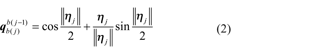
We assume that the attitude-updating period is

where
where
Hence, once
where
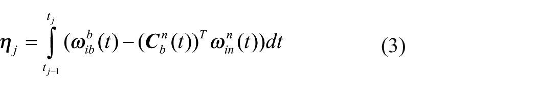
In time period
Then
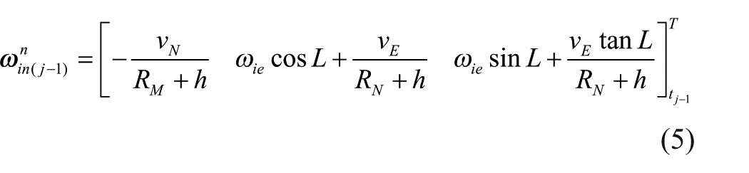
where
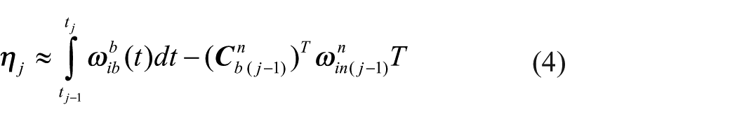
From equation (4), in order to calculate
As it is difficult to obtain the function of
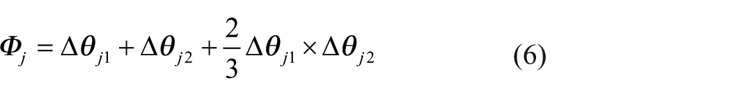
where
Thus,
After the attitude matrix of the vehicle is calculated, the heading and attitude angles of the vehicle can be calculated in real time.
Velocity and position-updating algorithms of DRS
After calculating the attitude matrix of the vehicle using attitude updating, the velocity and position of the vehicle can be calculated in real time using the velocity output of the Doppler radar. Thus, the velocity and position-updating processes are completed.
Let us assume that the velocity and position-updating periods coincide with the attitude-updating period and denote it as

(Equation 8) is the velocity-updating algorithm of DRS. When the navigation frame is the east–north–up geographic frame, the latitude
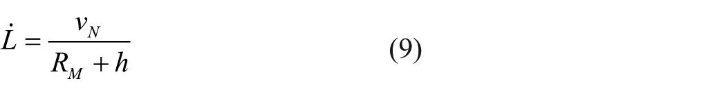

We assume that the latitude, longitude, and altitude of the vehicle position at moment

where ∆SEj, ∆SNj, and ∆SUj are the driving distance increments of the vehicle along the three axes of the navigation frame during
Because the vehicle velocity changes slowly in a short interval, the vehicle velocity during

According to the vehicle velocities
From equation (16), the driving distance increment ∆Sj during
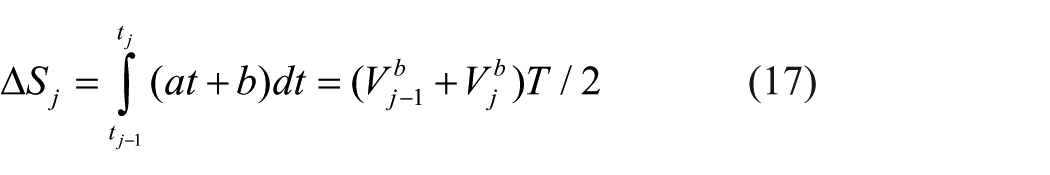
According to

By substituting equation (17) into equation (18),

Hence, the position updating of DRS can be achieved using equations (12)–(14) and (19).
Error models of the laser gyroscopes/Doppler radar DRS
Sensor errors, initial condition errors, algorithm errors, and other errors exist in actual DRS, which lead to attitude error, velocity error, and position errors of DRS. All these errors accumulate with time. Hence, error sources of DRS should be analyzed to establish the system error models, so as to design the filtering algorithm to estimate and modify system errors in the integrated position and orientation determination. Thus, the accuracy of the integrated position and orientation system can be improved.
Error models of the laser gyroscopes and Doppler radar
In the laser gyroscope/Doppler radar DRS, in addition to the initial condition and algorithm errors, sensor errors are the main error sources. Thus, sensor errors are mainly considered in this study, which are composed of gyroscope errors and Doppler radar errors.
With regard to the gyroscope errors, only the constant drift and white noise are left after calibration and compensation; thus, the gyroscope error can be described as follows

where

where
The errors in the velocity measurement of the Doppler radar are mainly caused by the installation angle error and the scale factor error. 21 The installation angle error of the Doppler radar can be compensated effectively by regular calibration. Thus, the scale factor error is necessary to be modeled, which is often considered as a random constant or a first-order Markov process.24,26 Thus, the first-order Markov process is adopted to describe the scale factor error of the Doppler radar in this study, that is

where
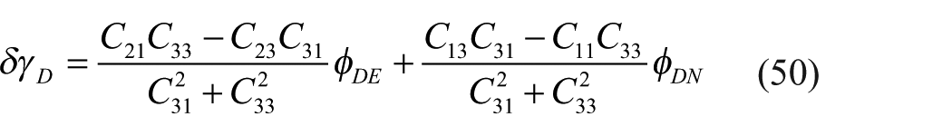
Attitude error equations of DRS mathematical platform
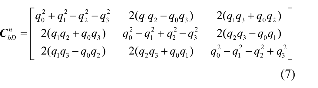
The attitude matrix
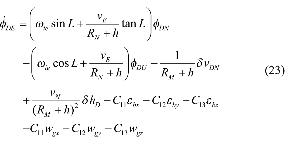
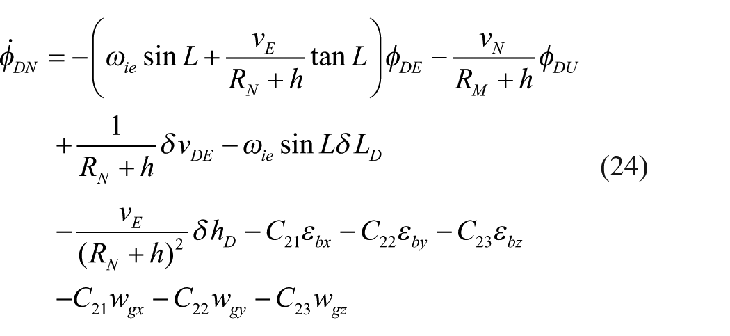
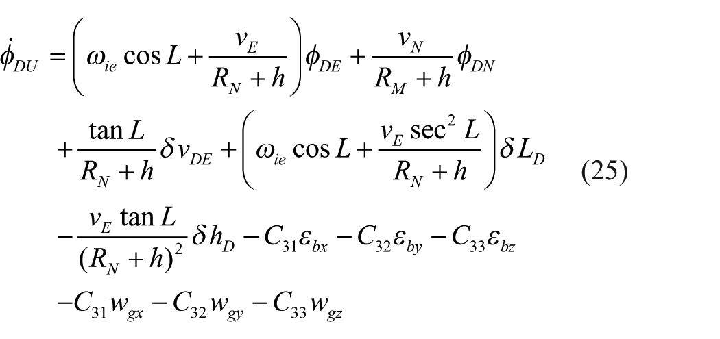
where
Velocity error equation of DRS
We assume that the vehicle attitude matrix calculated by DRS is
where
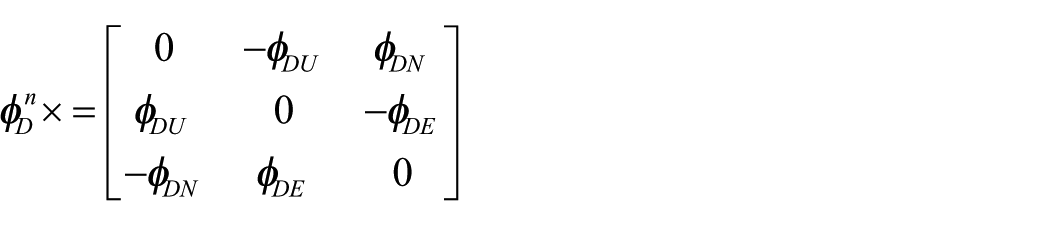
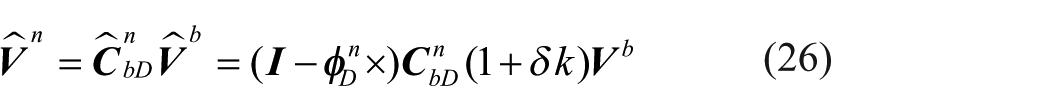
Expanding (26) and ignoring the second-order small values of the errors, the following equation can be obtained
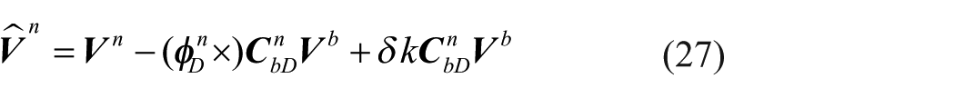
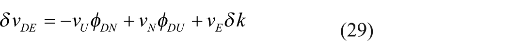
We assume that the velocity error of DRS in the navigation frame is

We assume that
Position error equations of DRS
Let us assume that the latitude, longitude, and altitude errors of DRS are

By expanding equations (32)–(34), ignoring the second-order small value of the errors, and comparing with equations (9)–(11), the following equations can be obtained
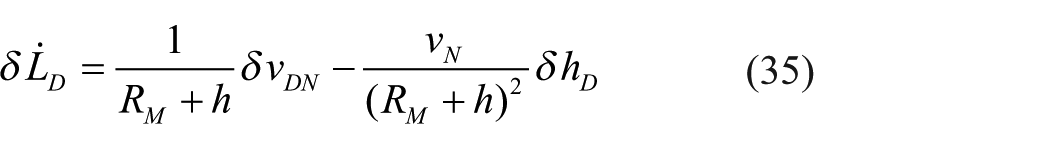
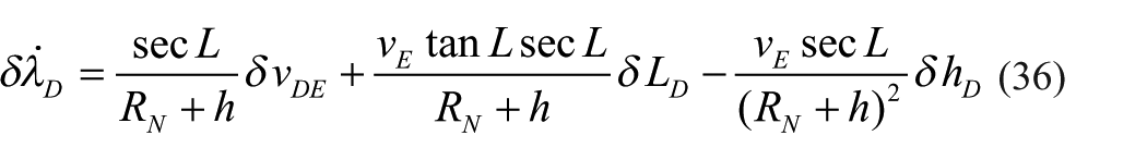

Then, substituting equations (29)–(31) into equations (35)–(37), the position error equations of DRS can be obtained as follows

Filtering algorithm of the integrated position and orientation based on SINS/Doppler radar
The errors of laser gyroscope/Doppler radar DRS slowly diverge with time; thus, DRS cannot achieve independent high-accuracy position and orientation for a long time. Furthermore, because DRS cannot autonomously accomplish initial alignment, it cannot autonomously determine the initial attitude of the vehicle. Therefore, DRS and SINS are integrated to achieve position and orientation in this study. This method can not only effectively restrain the divergence of the system error, but also determine the initial attitude of the vehicle with the assistance of SINS initial alignment. Furthermore, the system cost can be reduced by sharing the three laser gyroscopes of SINS. Hence, investigating the filtering algorithm of integrated position and orientation based on SINS/Doppler radar is necessary.
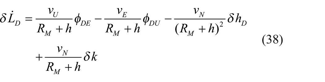
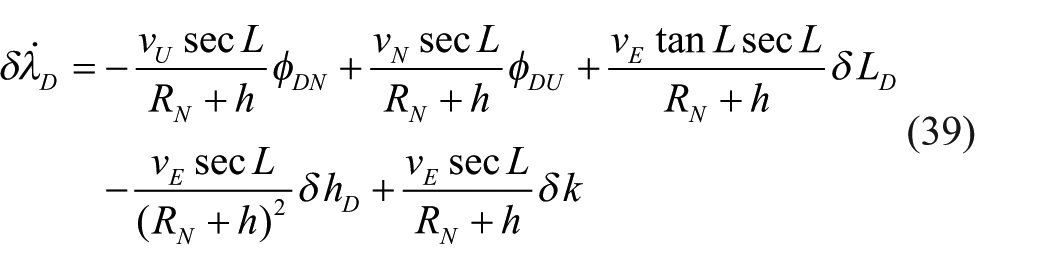
State equation of integrated position and orientation
The indirect filtering method is adopted in the design of the integrated position and orientation filtering algorithm. In this indirect filtering method, system errors are chosen as the system states of the filter. Because the error models of SINS have been researched and presented in many publications, they are ignored here. And the error models of the laser gyroscopes/Doppler radar DRS have been discussed in section “Dead-reckoning algorithm based on laser gyroscope/Doppler radar.” According to equations (29)–(31), a linear relationship clearly exists between the velocity errors and the mathematical platform attitude error of DRS. Hence, the velocity errors are not chosen as the system states of the integrated position and orientation filter. The white noises of the gyroscopes and accelerometers are considered as system noises and not as system states.
Thus, the system states of SINS/Doppler integrated position and orientation include the following: SINS mathematical platform attitude errors
According to the error models of SINS and DRS, and by combining these with the system state vector

where
Measurement equation of integrated position and orientation
In the current designs of the integrated position and orientation system based on SINS, the differences in the position or velocity outputs from each navigation subsystem are usually chosen as the measurements of the integrated position and orientation.27,28 However, because there is no measurement information on the vehicle’s attitude, the observability of SINS attitude errors is usually poor. Thus, the system attitude errors cannot be effectively estimated and compensated, and the attitude accuracy inevitably affects the position accuracy. Furthermore, during the navigation process, the errors of the attitude and position gradually diverge with time. Hence, in order to improve the accuracy of the position and orientation, we need to introduce the attitude information into the measurement of the integrated position and orientation.
Since both SINS and DRS can output the attitude, velocity, and position information of the vehicle, several choices are available for the measurement of the integrated position and orientation. The attitude information is introduced into the measurement in this study, and then the attitude and position of the vehicle are chosen as the measurement of the integrated position and orientation. The experimental results of attitude/position integration mode are compared with that of velocity/position integration mode to verify the effect of introduction of the attitude information.
Measurement equation of the attitude/position integration mode
In the attitude/position integration mode, the difference between the attitude output of SINS and that of DRS, and the difference between the position output of SINS and that of DRS are chosen as the measurements. Thus, the measurement of the attitude/position integration mode is expressed as
where
We assume that the heading, pitch, and roll errors of SINS are
For SINS, the relationship between the heading, pitch, roll errors, and the mathematical platform attitude errors satisfies the following equations
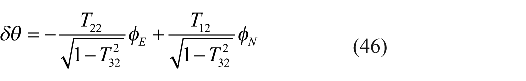
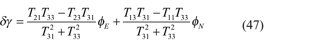
Here,
Similar to the above equations, for DRS, the relationship between the heading, pitch, roll errors, and the mathematical platform attitude errors satisfies the following equations
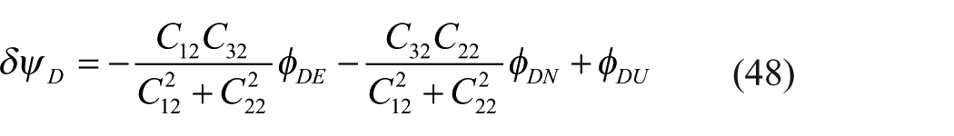
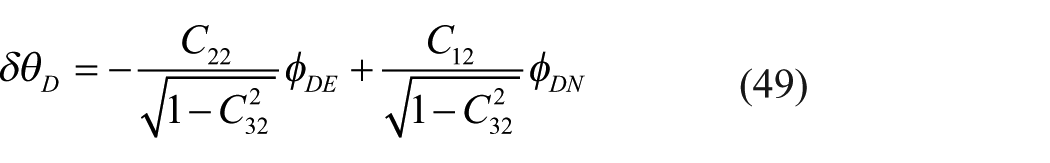
Here,
By substituting equations (45)–(50) into equation (44) and combining with the system state vector

where
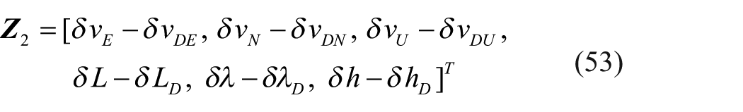
Measurement equation of the velocity/position integration mode
In the velocity/position integration mode, the difference between the velocity output of SINS and that of DRS, and the difference between the position output of SINS and that of DRS are chosen as the measurements. Therefore, the measurement of the velocity/position integration mode is
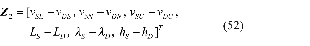
where
From equation (52), we have
Substituting equations (29)–(31) into equation (53), the following equation can be obtained
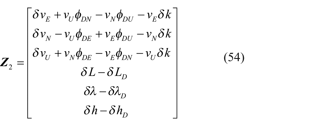
Thus, combined with the system state vector

where
After the state equation and measurement equation are obtained, the Kalman filtering algorithm can be adopted to perform the filtering calculation of the integrated position and orientation. Thus, the real-time estimations of system state
Experimental results
Simulation experiment results
First, we design and simulate the motion trajectory of the vehicle. In the trajectory designing, the actual motion states of the vehicle are simulated, which include uniform, acceleration, deceleration, turning, climbing, downslope, and stopping motions, as well as other forms of motion. Suppose that the initial position of the vehicle is at 34°14.763′ North latitude, 108°54.579′ East longitude, and 380 m above sea level. And suppose that the initial velocity of the vehicle is 0 m/s, the initial heading angle is 30°, the initial pitch angle is 0°, the initial roll angle is 0° (these angles are all randomly set), the driving time of the vehicle is 3600 s, the highest velocity is 22 m/s, and the total driving distance is 50.6 km. MATLAB is used to simulate the motion trajectory of the vehicle, and the corresponding motion parameters are obtained by the simulation. The three-dimensional curve of the motion trajectory is shown in Figure 2.
Motion trajectory of the vehicle.
Based on the aforementioned motion trajectory of the vehicle, SINS/Doppler radar integrated position and orientation method is simulated and verified. Suppose that the constant drift of the laser gyroscope is 0.01°/h and its random walk is
Position errors of the integrated position and orientation simulation experiment.
Attitude errors of the integrated position and orientation simulation experiment.
The above simulation results show that irrespective of the attitude/position or the velocity/position integration mode, the position and orientation results of SINS/Doppler radar integration are satisfactory. The errors of the position and orientation obviously do not diverge with time, and higher accuracy is achieved. These results prove that when the Doppler radar is used to assist SINS to achieve integrated position and orientation, the divergence problem of SINS errors can be effectively solved. Simultaneously, we can see that under the same motion trajectory and simulation conditions, the position and orientation accuracies of the attitude/position integration mode are higher than those of the velocity/position integration mode. When the filter reaches the stable state, the position error of the first integration mode is ±20.8 m (less than 0.05% of the total distance), the heading error is ±2.1′, and the horizontal attitude error is ±0.5′. However, the position error of the second integration mode is ±49.2 m (less than 0.1% of the total distance), the heading error is ±4.0′, and the horizontal attitude error is ±0.6′. In particular, during the navigation process, the position error of the attitude/position integration mode keeps good convergence, whereas that of the velocity/position integration mode shows a divergent trend. This simulation result shows that by introducing the attitude information into the measurement, not only the estimation effect of SINS attitude error is effectively improved (meaning that the orientation accuracy of the system is improved), but also the position accuracy of the system is improved. In addition, the errors of the integrated position and orientation can maintain good convergence for a long time.
Vehicular experiment results
Based on the laser SINS and Doppler radar existing in our research group laboratory, integrated position and orientation vehicular experiment is carried out. The vehicle and equipments used in experiment are shown in Figure 5. The constant drifts of laser gyroscopes in this laser SINS are better than 0.015°/h, and the random walks are better than
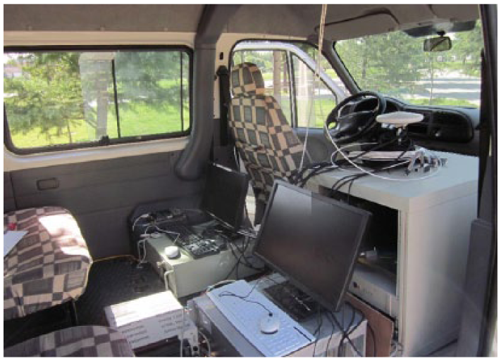
Vehicle and equipments used in the vehicular experiment.
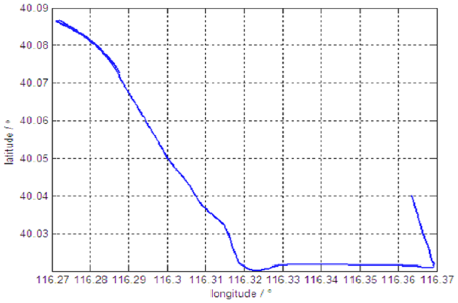
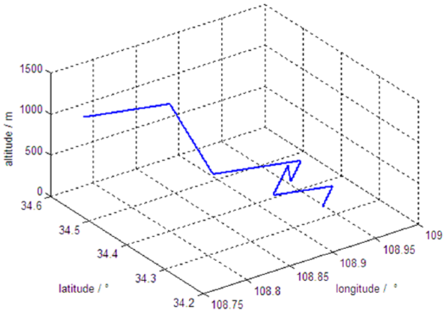
Plane motion trajectory of the vehicle.
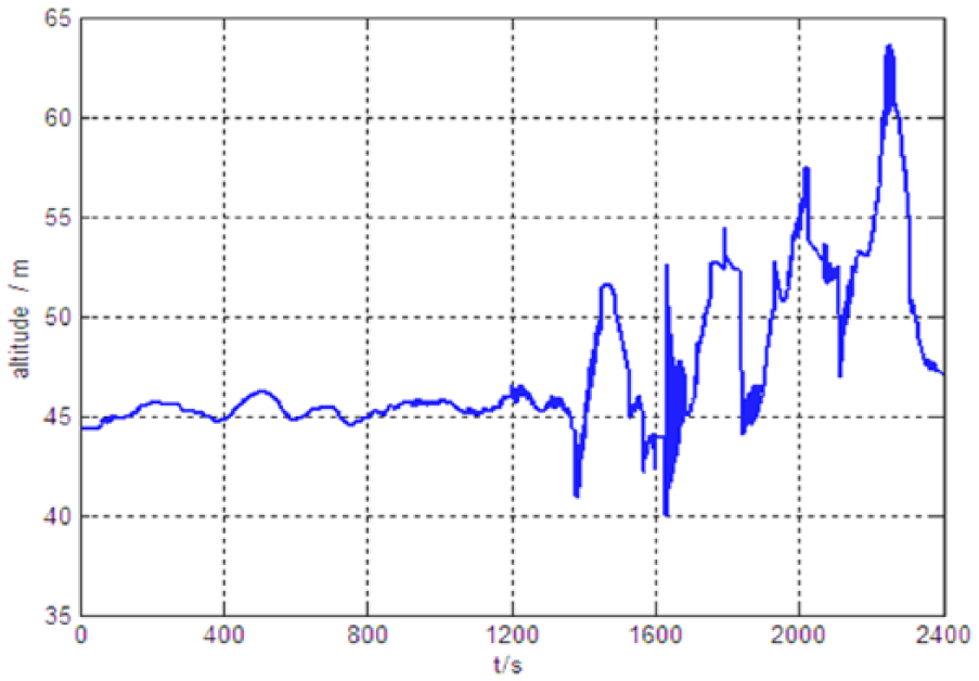
Altitude change curve of the vehicle.
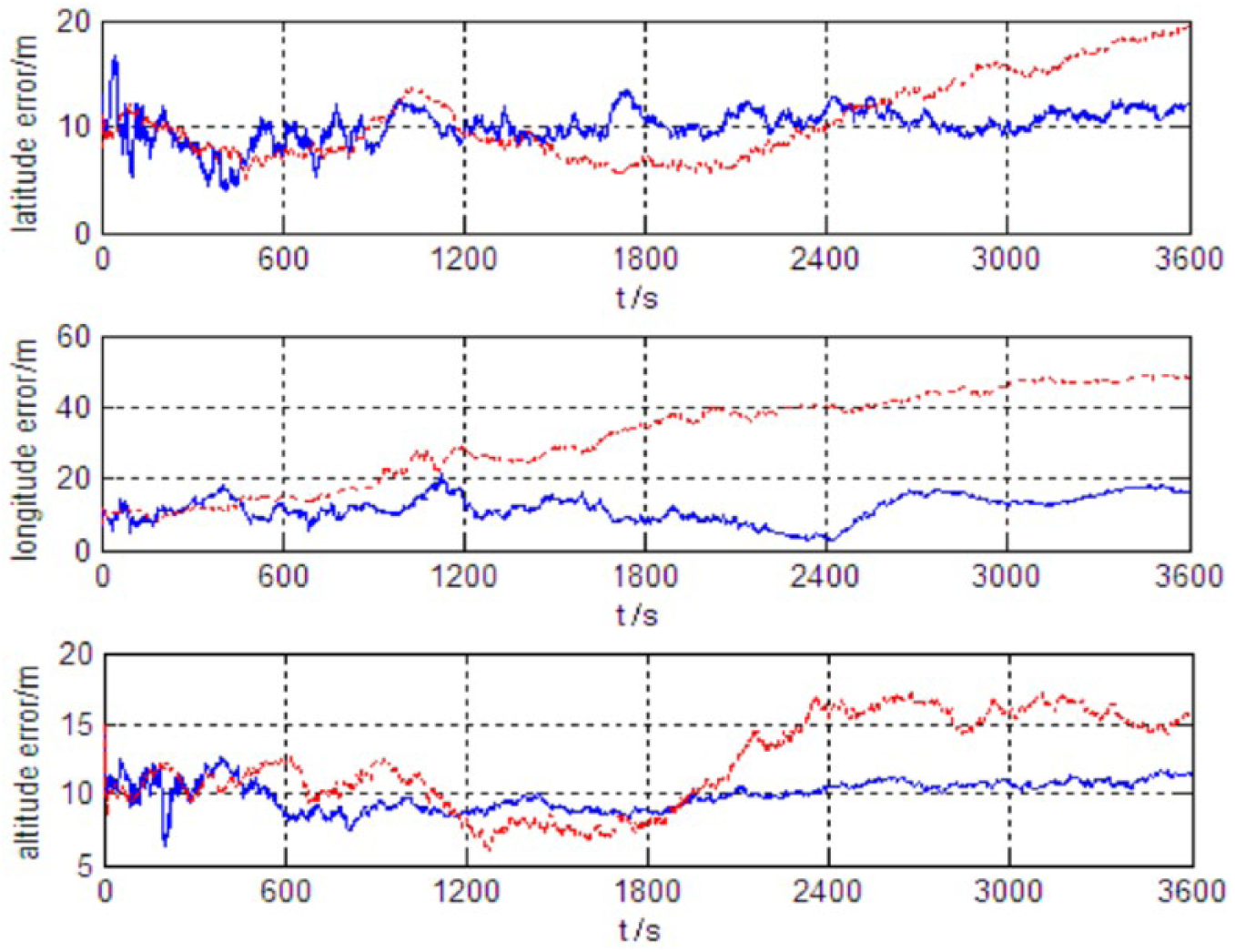
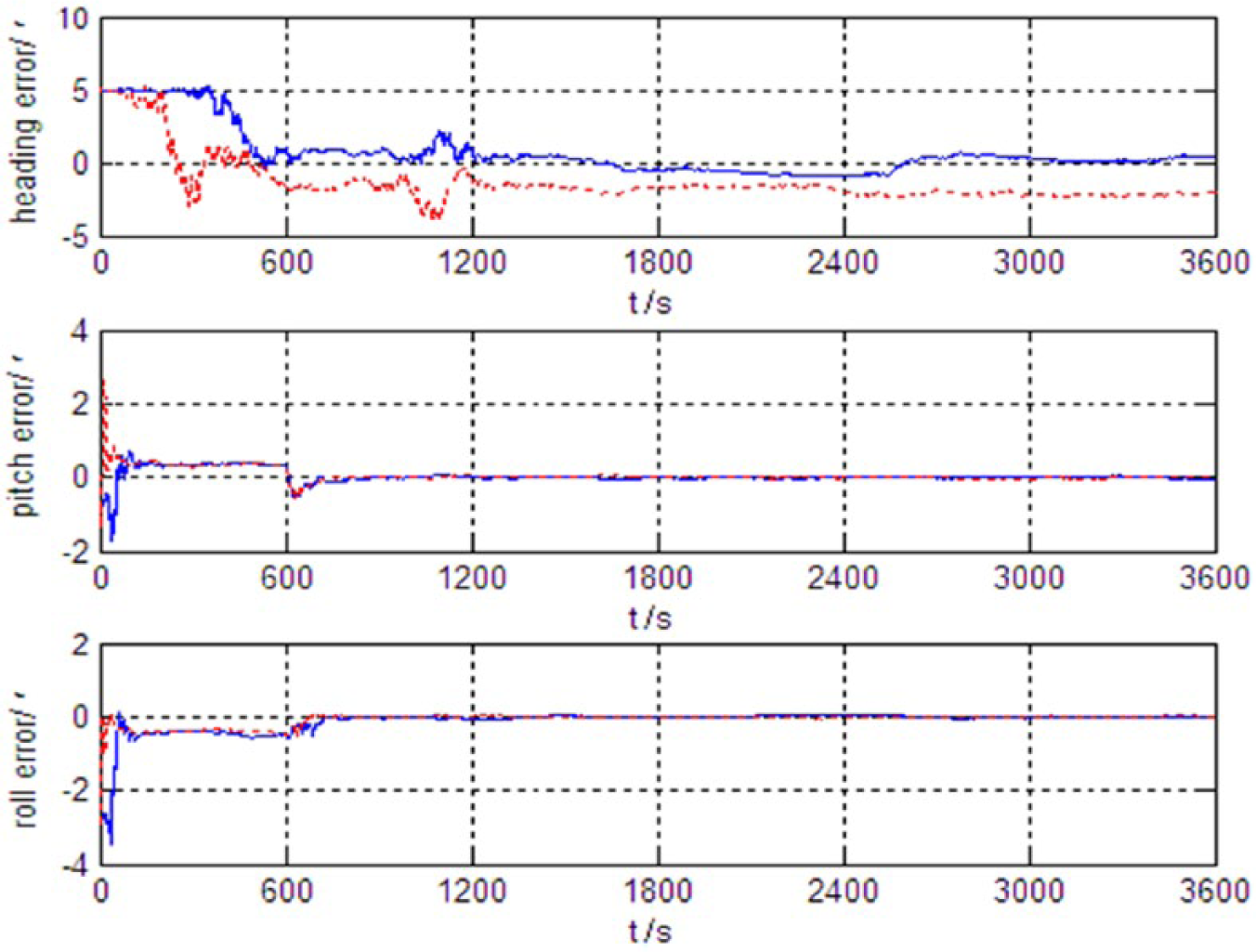
The position accuracy of the integrated position and orientation system is evaluated by the high-accuracy differential GPS, and the orientation accuracy is evaluated by the double antenna GPS orientation system. Thus, the vehicular experiment results of integrated position and orientation are shown in Figures 8 and 9. The same as the front simulation experiment result curves, the solid line indicates the experimental result of the attitude/position integration mode, and the dotted line indicates the experimental result of the velocity/position integration mode.
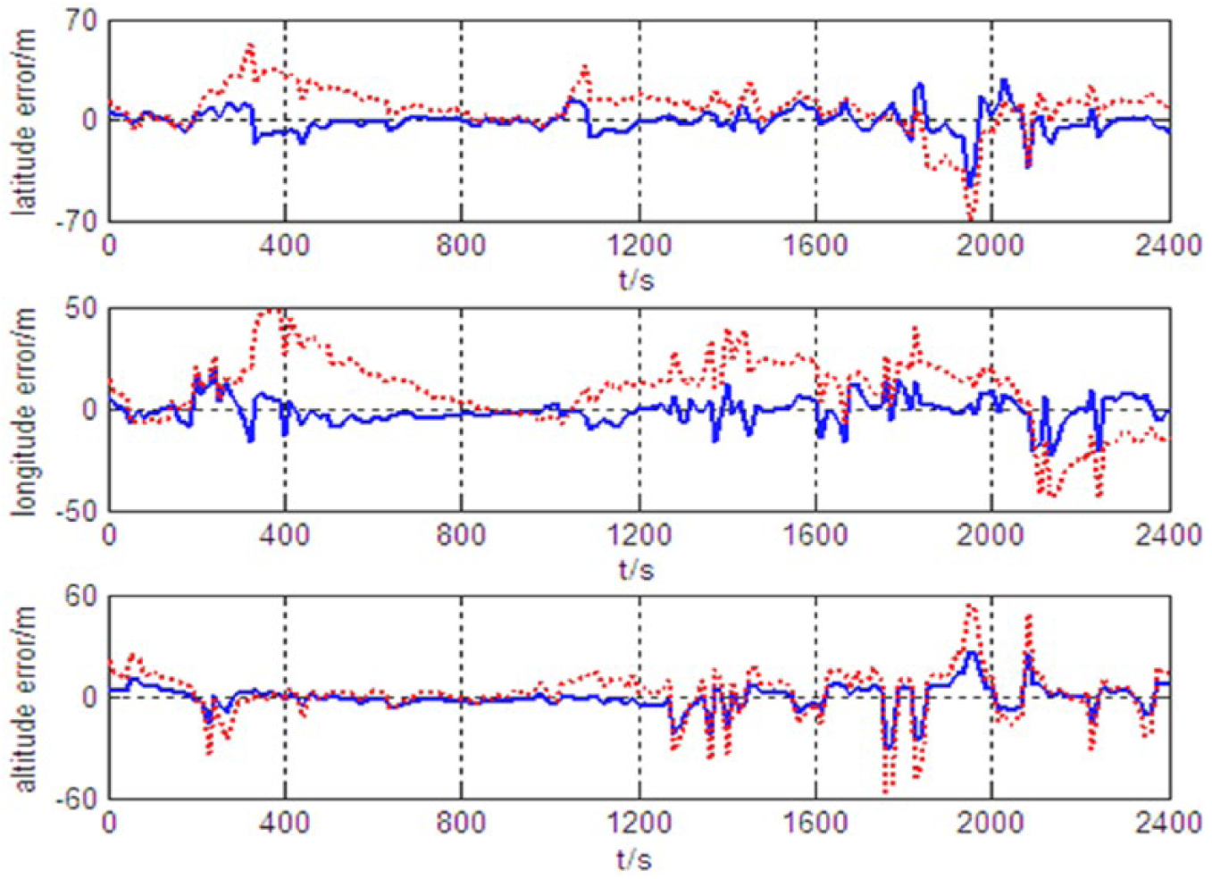
Position errors of the integrated position and orientation vehicular experiment.
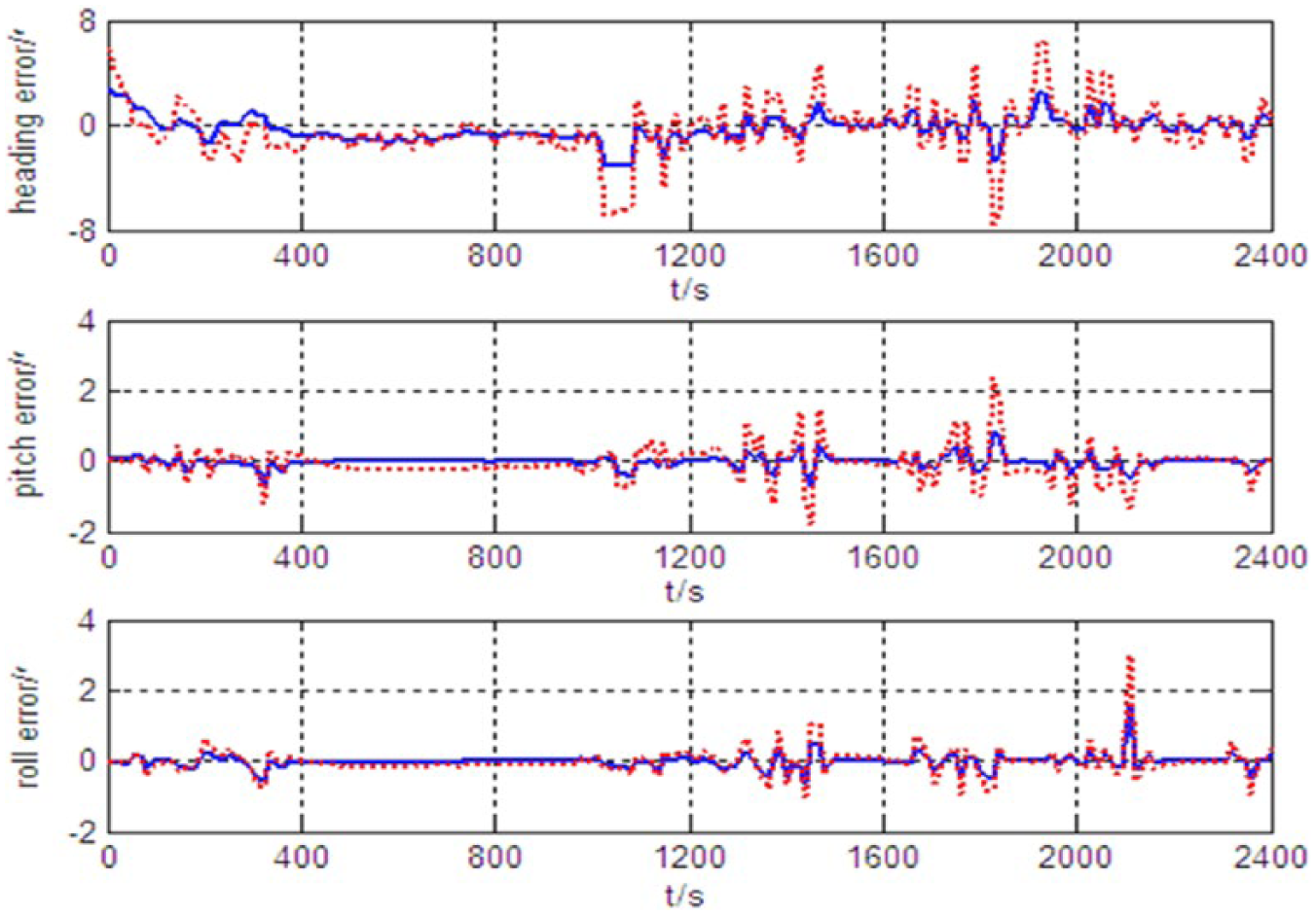
Attitude errors of the integrated position and orientation vehicular experiment.
According to the vehicular experiment results of the actual SINS/Doppler radar integrated position and orientation system, it can be seen that in the course of the 2400 s test, the horizontal position accuracy of attitude/position integration can reach ±27.9 m, the altitude accuracy reaches ±31.4 m, the heading accuracy reaches ±3.1′, and the horizontal attitude accuracy reaches ±0.8′. By contrast, under the velocity/position integration mode, the horizontal position accuracy reaches ±53.2 m, the altitude accuracy reaches ±54.9 m, the heading accuracy reaches ±6.7′, and the horizontal attitude accuracy reaches ±1.8′. Thus, it can be seen that SINS/Doppler radar integrated system can realize accurate positioning and orientation for vehicles for a long time, and the accuracy of attitude/position integration mode is significantly higher than the accuracy of velocity/position integration mode. Therefore, the attitude/position integration mode is more suitable for accurate position and orientation for vehicles.
At the same time, the results of the vehicular experiment show that the output signal of Doppler radar was not interrupted and was not disturbed by the external environment or the external electromagnetic signal in the course of the 2400 s test. In addition, although there are a lot of quick braking, rapid acceleration, large angle turning, and other maneuvers occurring in the course of vehicle driving, the results of integrated position and orientation have not been greatly affected. According to Figures 8 and 9, it can be seen that there are only a few instantaneous abrupt occurring in the position errors and attitude errors, and these errors quickly converge to the stable state. Especially, in the process of maneuver, the stability of attitude/position integration mode is obviously better than that of velocity/position integration mode. It is proved that besides high accuracy of velocity measuring, Doppler radar has the advantages of continuous output and good anti-jamming and can effectively avoid the measurement errors caused by the slipping or gliding of the vehicle. Therefore, Doppler radar is very suitable for assisting SINS to realize accurate positioning and orientation for vehicles.
Conclusion
In summary, a high-accuracy position and orientation method are presented in this paper, which has strong anti-jamming ability and good autonomy by adopting SINS and Doppler radar to determine the position and orientation of the vehicle. A dead-reckoning algorithm based on laser gyroscope/Doppler radar is proposed, and error models of DRS are developed. Then the filtering algorithm of SINS/Doppler radar integrated position and orientation is designed. The simulation experiment and vehicular experiment results show that the proposed position and orientation method not only solves the problem about the divergence of SINS errors, but also achieves accurate position and orientation for a long time. In particular, this method does not depend on any special maneuvering motion and can effectively avoid the measurement errors caused by the vehicle slipping or gliding. These fully prove the superiority of Doppler radar assisting SINS to realize positioning and orientation.
Consequently, the integrated position and orientation method based on SINS/Doppler radar offers the advantages of high accuracy, strong anti-jamming ability, good autonomy, high maneuverability, and excellent environmental adaptability. Therefore, this method has broad application prospects for the independent position and orientation of the vehicle.
Footnotes
Declaration of conflicting interests
The author(s) declared no potential conflicts of interest with respect to the research, authorship, and/or publication of this article.
Funding
This work is supported by the National Natural Science Foundation of China (grant no. 61503390) and the Natural Science Foundation of Shaanxi Province (grant no. 2016JQ6014).