
Abstract
In order to solve manual operation and low detection efficiency in the measurement of thread geometric error, machine vision and optical enlargement are adopted to measure the high-precision geometric error of thread. For screw thread edge image characteristics, a new method using 67.5° and 112.5° improved Sobel templates to obtain the edge of image was put forward, and we calibrated the system using self-calibration method. The geometric error measurement system of screw thread was designed. The geometric error of screw thread, such as pitch, angle and diameter of screw, were calculated by extracting the coordinates of image edge. The system can be concluded that the method of machine vision, whose linear precision is less than 10 μm, can be used to detect the comprehensive parameters of screw thread. The designed measurement system was intuitive, efficient and easy to operate. It can be used in modern manufacturing and has values in generalized application.
Introduction
Thread connection is applied to various fields in the machinery industry. 1 There are two measurement methods for detecting thread in mechanical manufacturing technology, single-parameter measurement and comprehensive measurement. 2 Using contact screw surface method with specialized gauge, a single parameter is obtained, and this method is a single-parameter measurement method. It often causes the wear of parts. Comprehensive measurement is an unworn method, which is implemented by the following step: using a large tool microscope, the thread profile is projected through the optical system in the field of eyepiece, and operation staff read out the thread parameters by measurement lens. The above two methods need to operate by handing the tools manually and cannot be tested online. The bulky equipment and the much detection procedure lead to the lower work efficiency and the higher detection cost, and the measurements are influenced by human factors. Contact test is also easy to damage the thread, the thread gauges used for inspection are easy to be worn that affect the testing accuracy and the cost of replacing the gauge is also high.
Machine vision technique mainly uses photoelectric imaging, computer image processing and pattern recognition technique to detect object. 3 Compared with traditional mechanical measurement methods, the advantage of it is non-contact detection. It improves the production efficiency and meets the needs of modern manufacture. Machine recognition technique, as a new detection and recognition technique, has obvious advantages and potential for development, and it has high speed, high precision, non-contact and strong anti-jamming capability. It can meet the requirements of the high efficiency of modern manufacturing, easily realize the online measurement in the process of production, conveniently detect errors in machining process and can make corrections in time. Therefore, it is widely used not only in the field of testing but also in the field of manufacturing and processing.4,5 The character of this technique has open interface, by which the user can improve the system function itself according to the need, so the system can adapt to the industrial automation field, and it will be more and more widely used in the real industrial production. The common detection of screw thread parameters adopt the full image of the orthographic projection, and there are two key problems with using this technique in practice. One is the incoordination between precision and range of measurement, and the high-precision results require enlarged images but the enlarged images cannot obtain a thorough boundary describing the parameter characteristics. The other is the shaded edge information because the helix angle of screw thread is ignored. Above two matters will lead to lower precision, this is why the vision machine technique is difficult to use in required high-precision measurement situation. In this article, we settled the problem of image shelter using deflecting the spindle that was adjusted by screw helix angle. By using the way that orthogonal projection axis section unilateral image combined with moving workbench, we solved the problem of low precision in the image measurement processing. Using digital image processing technology and axial section images, we proposed the method of high-precision comprehensive measurement for geometric errors of thread parts.
System design
Figure 1 showed the measurement system designed. The measurement system detecting screw thread geometric error were made of charge-coupled device (CCD) image sensor, image acquisition card, light source, universal tool microscope and computer. 6 The image acquisition environment consisted tool microscope and light source, by which the external noise should be minimized in the process of the measurement. Due to the thread image affected by the helical line, the vertical pillar was readjusted according to spiral angle theory value every time. The image collected by CCD was inputted by image capture card and digitally processed by computer. The edge image of screw was obtained through preprocessing and extraction of profile curve, so the geometric error of screw was comprehensively measured. 7
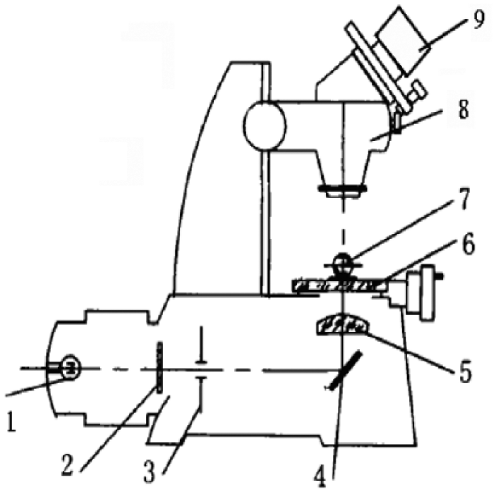
Mechanical structure and the optical system.
Improved algorithm for edge extraction based on direction
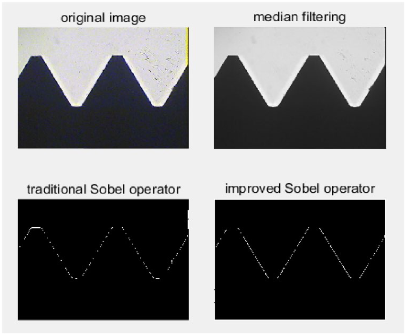
The collected image of screw is depicted in Figure 4. For the whole image processing system, the image preprocessing selectively highlights the important part of the image and remove unnecessary features. Image inevitably contains noise because of the influence of surrounding environment. The noise is random, so it distributes irregularly. The filtering and noise reduction of image are required in order to avoid image distortion. The method should be according to the characteristics of the noise itself. The noise of the thread image arises from the surface of thread rust and burrs. Eliminating noise and retaining most useful information of the edge, the median filtering is particularly useful. 8
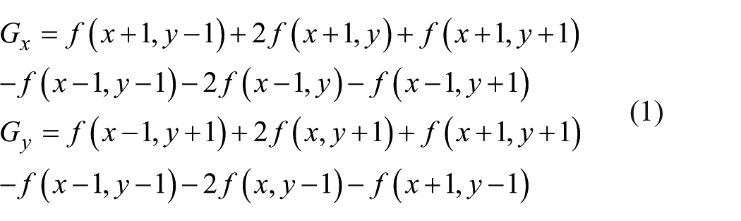
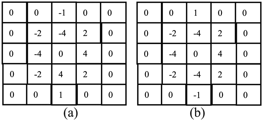
There are many common edge detection operators such as Sobel operator, Canny operator and Robert operator. These commonly used detection algorithms are based on the gray value of original image, and the edge is detected according to the grayscale change in a neighborhood of each pixel. 9 The classic Sobel operator has two perpendicular templates, and any point f(x, y) in the image can convolution calculated by using them. Using Equation (1), we can obtain the G(x) and G(y) of two directions, and the gradient amplitude of the whole image M(x, y) can also be calculated by Equation (2). A detected point is considered a marginal point when the gradient amplitude of this point is greater than a given threshold value. Figure 2 shows a horizontal gradient template and a vertical gradient template, which mainly detects the vertical edge and horizontal edge of the image
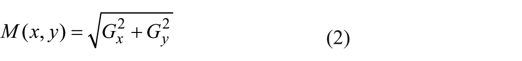
Traditional Sobel operator: (a) horizontal direction template and (b) vertical direction template.
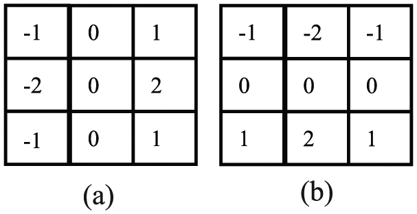
The advantages of Sobel operator are the simple principle, the less calculation and the faster operation speed. The traditional templates only use horizontal and vertical direction templates which were sensitive only to both horizontal and vertical edges, but the image texture of screw has more complex oblique edge, so the extraction of edge is not ideal and the anti-noise performance is poor. The original image of thread in Figure 4 mainly includes oblique edge but the traditional Sobel algorithm detects the horizontal and vertical edge of the image. And the geometric error of screw thread, such as thread angle, pitch and medium diameter, is measured based on oblique edge. Therefore, the accuracy of oblique edge extraction will directly affect the measurement of thread geometry parameters. According to the characteristics of the image captured by projector measuring external thread geometry parameter, an improved Sobel operator, 67.5° and 112.5° direction templates, was proposed as shown in Figure 3(a) and (b). Each pixel in the image was convolution calculated by these two matrices and was composited following Formula (2); the computed value was used as the new grayscale of the detected pixel and the template direction corresponding to the maximum value was the edge direction of this pixel. As shown in Figure 4, the improved Sobel algorithm increased weighting of slant line, and the image edge was obviously more precise and continuous than the image edge using the original operator, which was more favorable for the edge extraction. The refinement of the gradient image included three steps. First, it was found that the maximum value of diagnostic window (3 × 3 neighborhood) centered on the research point (x, y).Second, the local threshold was set according to the maximum value of diagnostic window. Finally, the image binary treatment was processed based on the slant direction, which maintains the continuity of the edge and refinement information 10
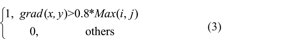
where grad(x, y) is the gradient of research point (x, y) and Max(i, j) is the maximum value of diagnostic window centered on (x, y).
Improved Sobel operator: (a) 67.5° direction template and (b)112.5° direction template.
Algorithms comparison.
Materials and methods
The integrated measurement system for thread parameters based on machine vision was made of OK series monochrome camera with high-resolution scanning produced by JiaHeng Company and OK-CL20A Camera link digital image acquisition card.
Calibration
Using enlarged optical lens, we calibrate the measurement system before use, which is necessary for measurement. 10 The corresponding relation between image space and object coordinate space is obtained, by which the relationship between CCD pixels and the actual geometry of the measured work piece is determined. In this article, we use the method of self-calibration. The parts to be tested are installed on the two-dimensional working platform that is controlled by the precise displacement by grating ruler. One of the platforms is stationary, another moves when the measurement is operated. The image is collected by CCD on the basis of field of view again and again. After the above procedure, the captured images are processed. Taking a feature point on the edge of the image as a reference point, we obtained a line in coordinate system that the pixel value of this point was adopted as horizontal axis and the actual moving distance of the grating as the vertical axis. The slope of this straight line was the calibration coefficient. The x-direction and y-direction were both calibrated, and the calibration coefficients were different. Figure 5 shows that the y-direction calibration coefficient ky is 0.0051 (mm pixel−1) and x-direction calibration coefficient kx is 0.0049 (mm pixel−1), and the slope of straight line about x-direction is negative because the motion is going in the negative direction of x. Actual geometric parameter values are calculated by the calibration coefficient multiplied by all the pixel values described by geometric parameter.
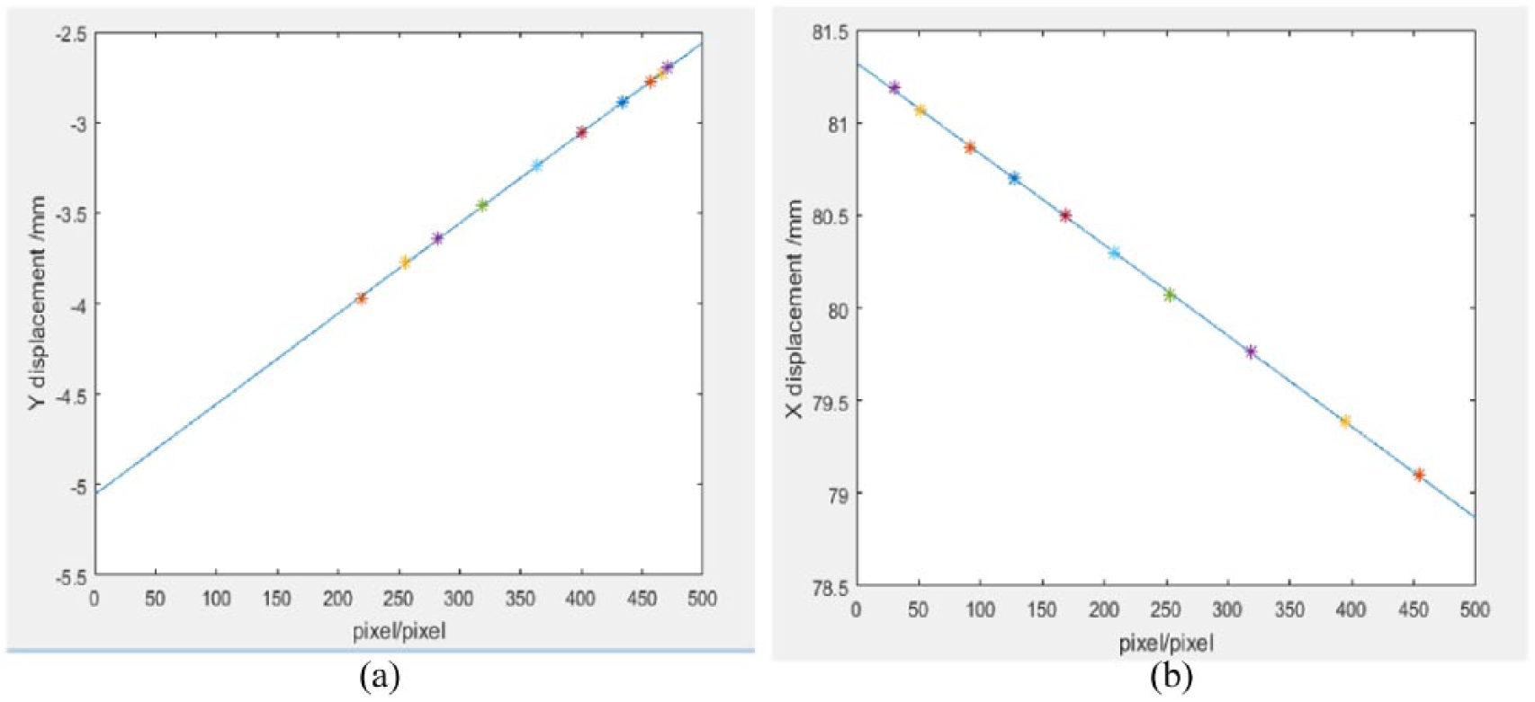
Calibrated-coefficient straight line: (a) y-direction and (b) x-direction.
Pitch diameter of thread
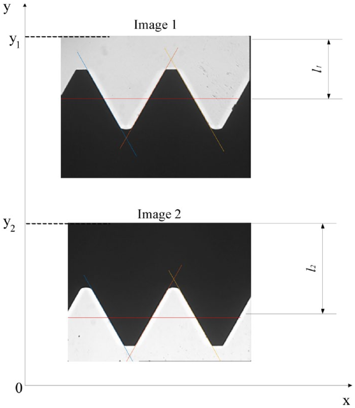
Pitch diameter of thread is a diameter of hypothetical cylinder whose generating line has the same size between the width of the groove and the width of the protrusion. 11 The locations of thread diameter are successively described as E1F1 and E2F2 in Figure 6. Using transformation of coordinate system as shown in Figure 7, we can obtain the value of thread diameter according to the movement of y axis

where d2 is the thread diameter and ky is the calibrate coefficient of y-direction. y and l are the grating coordinate and image coordinate of two sampling images during the measurement process, respectively.
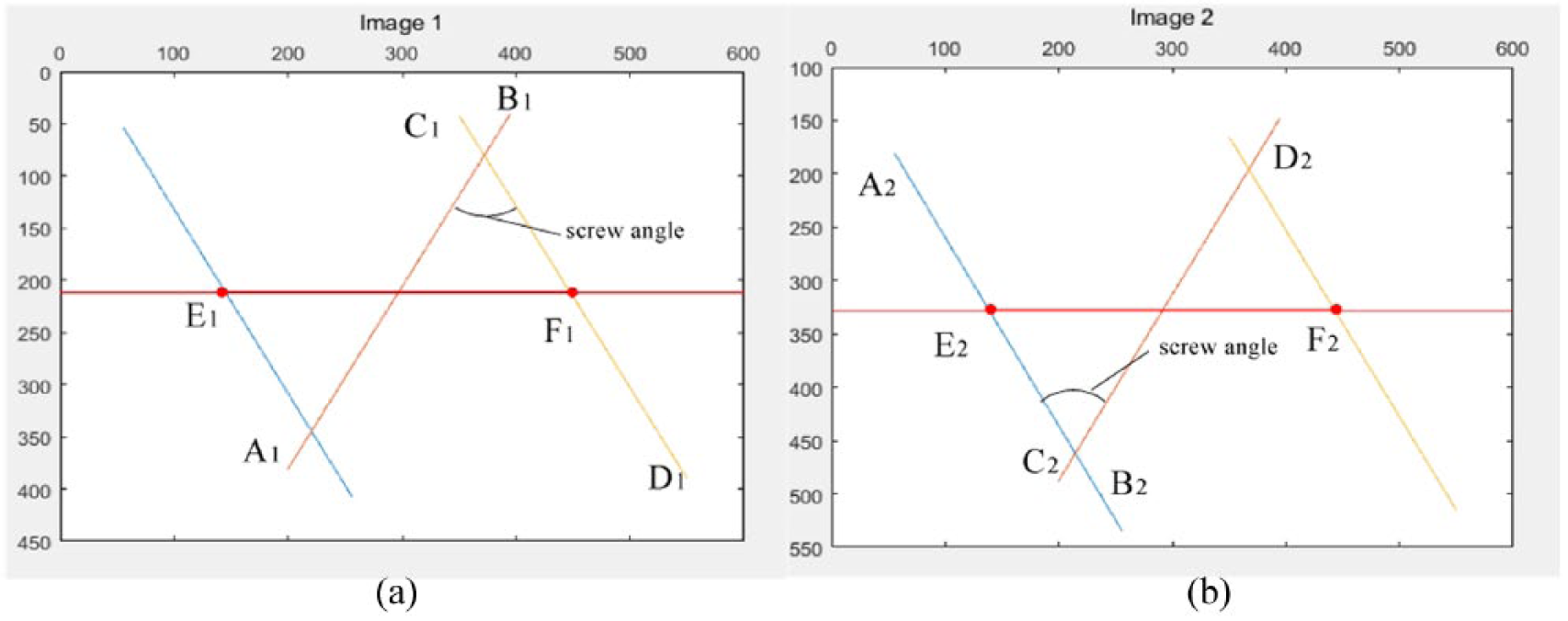
Geometric error sketches of screw thread: (a) image 1 and (b) image 2.
Transformation of coordinate system between imaging and measuring.
Pitch
The thread pitch is the axial distance between two adjacent shape-V forms on the middle diameter. As shown in Figure 6, the pixel value of thread pitch EF can be calculated from images when the location of diameter was found. Thread pitch P0 can be obtained from

Thread angle
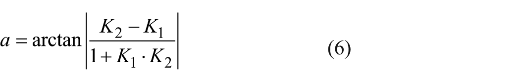
Thread angle is the angle between two adjacent threads on the cross-sectional shape. Extracting the information of edge from the captured images, the empirical formula about regression line AB and CD can be calculated using the least square method, and the slopes of two straight lines K1 and K2 were acquired. Thread angle α is given by
Conclusion
Using MATLAB programming environment, the measurement software of synthesis parameter was designed. The flow pattern and procedure interface of software were shown in Figures 8 and 9.
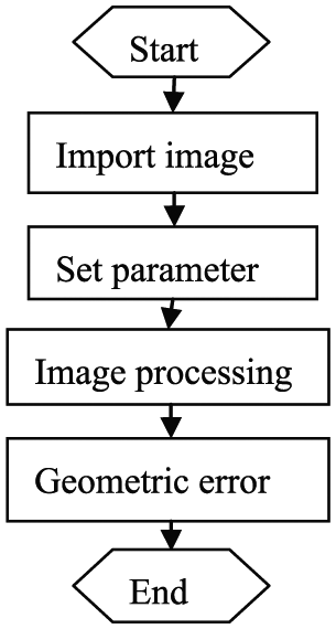
Software flow pattern.
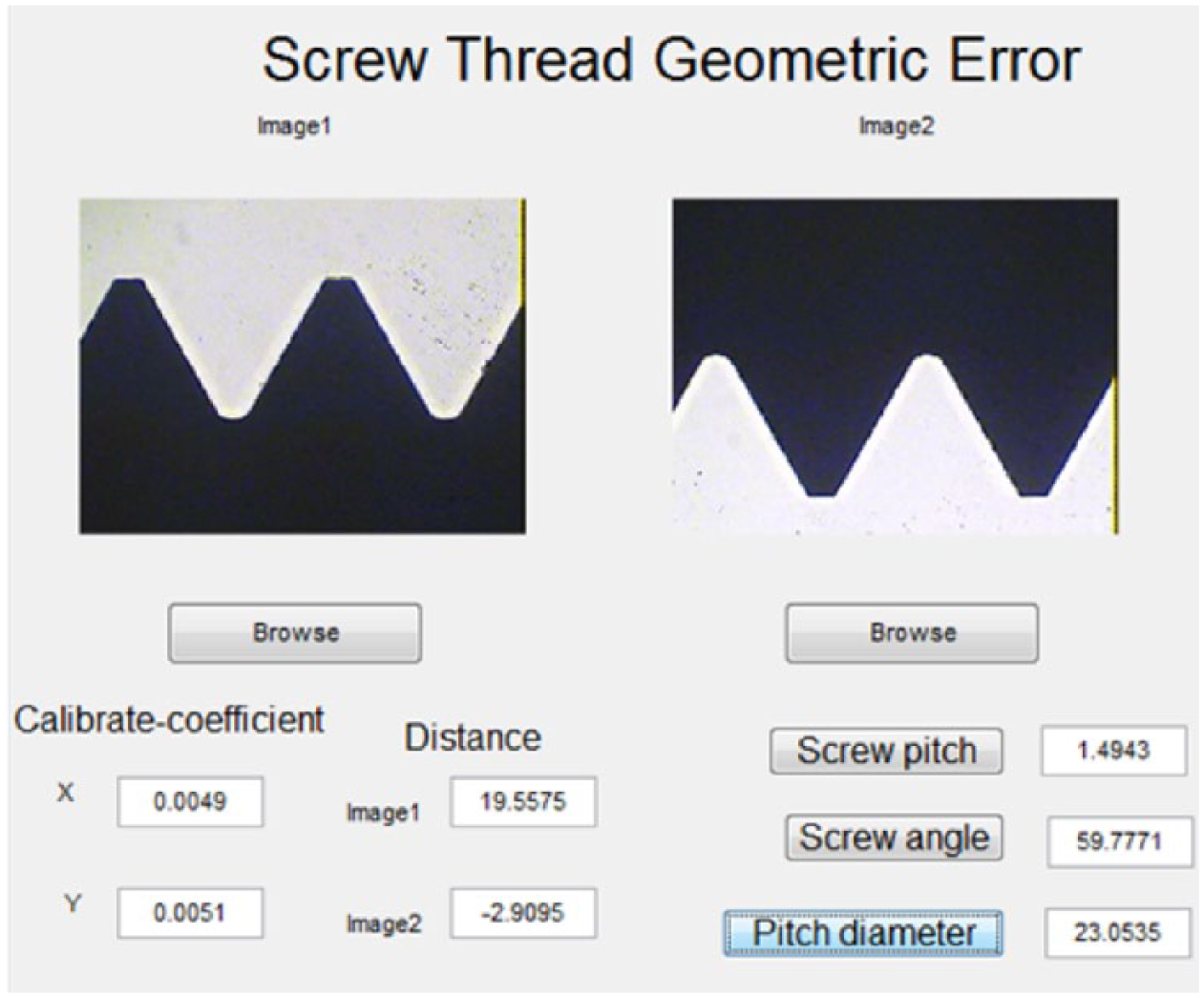
Procedure interface.
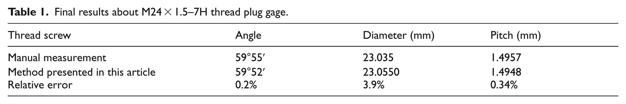
Taking M24×1.5–7H thread plug gage as example, the axial section graphs were analyzed and the geometrical errors were computed. Table 1 shows the final results such as thread angle, pitch and diameter, comparing between the manual measurement method and method presented in this article. The theoretical value of thread angle is 60°, and all the data are on average collected by 15 measurements.
Final results about M24 × 1.5–7H thread plug gage.
Discussion
From the above analysis, it can be seen that the method of machine vision can quickly detect the geometrical parameters such as thread angle, thread diameter and thread pitch and have certain precision. The minimum size of the CCD photosensitive sensor unit determines the accuracy of this method. In this measurement, the minimum size of the sensing unit of the measurement system is 8.3 μm, so the linear precision of this system is less than 10 μm.
Found in the experiment, there were many factors which influence measurement error, such as the interference of outside light source, adjustment of the focal length of microscope and lens distortion. Subsequent research will focus on improving the measurement accuracy by perfecting the experiment environment and researching new algorithms.
In this article, we have presented a new improved oblique template according to the characters of the thread edge. Using this improved Sobel templates, the thread edge have higher resolution details and continuity as compared to traditional Sobel templates. According to the strict definition of thread angle, pitch, middle diameter, and the geometric errors of thread have been calculated by using the thread cross-sectional image. The measurement software has been designed and the artificial judgment has not been necessary in the whole process, which could reduce the measurement error. Comparing the traditional artificial measurement, this method has high speed, high precision and good applicability. It can realize the on-line automation measurement of thread, which provides a reference for batch testing thread in production.
Footnotes
Declaration of conflicting interests
The author(s) declared no potential conflicts of interest with respect to the research, authorship and/or publication of this article.
Funding
The author(s) received no financial support for the research, authorship and/or publication of this article.